EP1491702A1 - Inspection cover - Google Patents
Inspection cover Download PDFInfo
- Publication number
- EP1491702A1 EP1491702A1 EP04014700A EP04014700A EP1491702A1 EP 1491702 A1 EP1491702 A1 EP 1491702A1 EP 04014700 A EP04014700 A EP 04014700A EP 04014700 A EP04014700 A EP 04014700A EP 1491702 A1 EP1491702 A1 EP 1491702A1
- Authority
- EP
- European Patent Office
- Prior art keywords
- inspection
- plate
- cover
- edge
- opening
- Prior art date
- Legal status (The legal status is an assumption and is not a legal conclusion. Google has not performed a legal analysis and makes no representation as to the accuracy of the status listed.)
- Granted
Links
- 238000007689 inspection Methods 0.000 title claims description 96
- 238000005192 partition Methods 0.000 claims description 13
- 239000000463 material Substances 0.000 claims description 10
- 238000010276 construction Methods 0.000 claims description 7
- 210000002105 tongue Anatomy 0.000 claims description 7
- 238000009434 installation Methods 0.000 claims description 6
- 239000003063 flame retardant Substances 0.000 claims description 5
- 238000003780 insertion Methods 0.000 claims description 5
- 230000037431 insertion Effects 0.000 claims description 5
- OSGAYBCDTDRGGQ-UHFFFAOYSA-L calcium sulfate Chemical compound [Ca+2].[O-]S([O-])(=O)=O OSGAYBCDTDRGGQ-UHFFFAOYSA-L 0.000 claims description 4
- 229910052751 metal Inorganic materials 0.000 claims description 4
- 239000002184 metal Substances 0.000 claims description 4
- 239000003795 chemical substances by application Substances 0.000 claims description 3
- 239000006260 foam Substances 0.000 claims description 3
- 239000010440 gypsum Substances 0.000 claims description 3
- 229910052602 gypsum Inorganic materials 0.000 claims description 3
- OKTJSMMVPCPJKN-UHFFFAOYSA-N Carbon Chemical compound [C] OKTJSMMVPCPJKN-UHFFFAOYSA-N 0.000 claims description 2
- 229910000831 Steel Inorganic materials 0.000 claims description 2
- 229910052918 calcium silicate Inorganic materials 0.000 claims description 2
- 239000000378 calcium silicate Substances 0.000 claims description 2
- OYACROKNLOSFPA-UHFFFAOYSA-N calcium;dioxido(oxo)silane Chemical compound [Ca+2].[O-][Si]([O-])=O OYACROKNLOSFPA-UHFFFAOYSA-N 0.000 claims description 2
- 238000013461 design Methods 0.000 claims description 2
- 239000010439 graphite Substances 0.000 claims description 2
- 229910002804 graphite Inorganic materials 0.000 claims description 2
- 230000000149 penetrating effect Effects 0.000 claims description 2
- 229910001220 stainless steel Inorganic materials 0.000 claims description 2
- 239000010935 stainless steel Substances 0.000 claims description 2
- 239000010959 steel Substances 0.000 claims description 2
- 238000009423 ventilation Methods 0.000 claims description 2
- 238000012423 maintenance Methods 0.000 abstract 1
- 239000004566 building material Substances 0.000 description 9
- 230000009970 fire resistant effect Effects 0.000 description 7
- 238000011161 development Methods 0.000 description 3
- 230000018109 developmental process Effects 0.000 description 3
- 238000000034 method Methods 0.000 description 2
- 238000007789 sealing Methods 0.000 description 2
- 239000010751 BS 2869 Class A2 Substances 0.000 description 1
- 238000005260 corrosion Methods 0.000 description 1
- 230000007797 corrosion Effects 0.000 description 1
- 230000001419 dependent effect Effects 0.000 description 1
- 239000011094 fiberboard Substances 0.000 description 1
- 239000000203 mixture Substances 0.000 description 1
- 230000003287 optical effect Effects 0.000 description 1
- 238000012545 processing Methods 0.000 description 1
- 230000001105 regulatory effect Effects 0.000 description 1
Images



Classifications
-
- E—FIXED CONSTRUCTIONS
- E04—BUILDING
- E04F—FINISHING WORK ON BUILDINGS, e.g. STAIRS, FLOORS
- E04F19/00—Other details of constructional parts for finishing work on buildings
- E04F19/08—Built-in cupboards; Masks of niches; Covers of holes enabling access to installations
- E04F19/083—Covers with fixing means providing for snap locking
-
- E—FIXED CONSTRUCTIONS
- E04—BUILDING
- E04B—GENERAL BUILDING CONSTRUCTIONS; WALLS, e.g. PARTITIONS; ROOFS; FLOORS; CEILINGS; INSULATION OR OTHER PROTECTION OF BUILDINGS
- E04B9/00—Ceilings; Construction of ceilings, e.g. false ceilings; Ceiling construction with regard to insulation
- E04B9/003—Ceilings; Construction of ceilings, e.g. false ceilings; Ceiling construction with regard to insulation with movable parts, e.g. pivoting panels, access doors
Definitions
- the invention relates to a revision cover for closing an inspection opening on walls, ceilings, shafts, installation or ventilation ducts according to the preamble of claim 1.
- Building material class A includes non-combustible building materials.
- the combustible building materials are classified in class B.
- Class A is subdivided further.
- A1 building materials must be completely non-combustible in their composition, while A2 building materials may contain a small amount of flammable components.
- non-combustible board material always means at least one building material of class A2.
- a revision cover which consists of a flat, non-combustible plate which is formed except for a gap remaining in the edge region of the inspection gap precisely to this, wherein in the gap a frothy in case of fire intumescent is arranged.
- Such inspection opening for wall and ceiling installation are used for example in conjunction with the cover of located behind a wall or a ceiling of a building electrical or sanitary installations. Since the installations must be freely accessible at least in an emergency, recesses (so-called inspection opening) are usually provided on the wall or ceiling paneling, which are provided with a revision cover.
- the inspection covers must have a have sufficient fire resistance duration.
- This fire resistance time is at least 30 minutes for fire-retardant constructions, and at least 90 minutes for fire-resistant constructions.
- the proposed solution is at least fire-retardant, but this logically includes fire-resistant constructions.
- the invention has for its object to reduce the installation and material costs while ensuring the required fire resistance period.
- the prefabricated plate according to the invention including the cover plate, which is preferably made of metal, as well as the diverse designable fastening elements (see below), the cover plate also serving to cover the gap.
- the inspection cover is designed as a prefabricated component, d. H.
- the corresponding point according to the dimensions of the inventive revision cover is rebuilt in the construction of the fire-retardant or fire-resistant or it is a prefabricated partition wall element set up with revision that fits exactly the prefabricated revision cover on the one hand and on the other hand directly with other partition elements can be converted ,
- the partition wall element with inspection opening is thus at the same time partition and recording for the inspection cover. It must be introduced in this preferred embodiment neither subsequently a corresponding opening by means of a saw, nor a frame must be fixed in the opening. This mounting method will be explained in more detail below.
- the inspection cover shown in each of FIGS. 1 to 15 for closing an inspection opening 1 on walls and ceilings generally consists of a flat, non-combustible plate 2 which, with the exception of a gap 3 remaining in the edge region of the inspection opening 1, is designed to fit precisely thereto.
- an intumescent film-forming agent 4 which foams in the event of fire, preferably so-called expanded graphite or another intumescent material, is arranged.
- the intumescent layer 4 may optionally be arranged at the edge of the inspection opening 1 or on the inspection cover (see in particular Figures 1, 2 and 5).
- a gap 3 covering prefabricated and preferably made of metal or Plastic existing cover plate 5 is arranged and the plate 2 frameless insertion into the inspection opening 1 and by means of the fastening elements 14, preferably screws 9, at the edge 6 is fastened fastened.
- the plate 2 consists of at least two mutually stepped layers 7, 8, and that the edge 6 of the inspection opening 1 is configured in a correspondingly stepped manner for the positive insertion of the cover. Accordingly, the gap 3 in two- or multi-layered design of the plate 2 has a gradual course. This is on the one hand in terms of fire protection advantageous (improved sealing), on the other hand, this advantageously also corresponds to the usual structure of fire-resistant walls, namely regularly consist of two mutually offset layers mounted.
- the plate 2 is also advantageously provided that it consists of non-combustible material such as calcium silicate and calcium sulfate and is at least 20 mm thick.
- the gap 3 in this case preferably has a width of about 1 to 8 mm. If the inspection opening is introduced suburb in the partition, this can for example be done with a jigsaw or circular saw or a circle cutter (round inspection covers). In this case, the edge of the inspection opening will not regularly be formed in stages (see, for example, Figure 12 and 14).
- the inspection cover is, as shown particularly clearly in Figure 2, provided that the plate 2 is secured with screws 9 at the edge 6 of the inspection opening 1. In this case, 5 through openings 13 for the screws 9 are introduced at the edge of the cover plate.
- the fastening elements or screws 9 can be brought into engagement with clamps 17 arranged on the edge of the inspection opening 1, wherein the clamps 17 surround the edge of the inspection opening 1 in a U-shape and preferably with screws 18 are attached.
- the screws 9 for fastening the inspection cover are made long enough to be able to compensate for changes in distance of the cover plate 5 to the edge 6 of the inspection opening 1, for example by tiles 10 applied there (see FIG. 2).
- the cover plate 5 is advantageously provided that it projects beyond the gap 3 at least 20 mm and just like the plate 2 has a rectangular, preferably square base with the dimensions of 300 mm x 300 mm to 900 mm x 900 mm.
- the inspection opening and cover can also be round (see in particular FIGS. 11, 13 and 15) and have a free engagement diameter of 50 mm (socket-like) up to 900 mm.
- the cover plate 5 is optionally preferably made of metal (especially stainless steel) or plastic (especially in ceiling access openings in which the fasteners do not attack directly on the cover) and can for optical reasons, as shown in Figure 4, at their edges a Edge of the access opening 1 have folded out area.
- U-shaped rails 11 are first erected vertically (or horizontally suspended) in front of a wall (or ceiling). At these a first layer of non-combustible plates is attached.
- the partition thus consists of a first layer with a revision opening, which is formed from a prefabricated, two-layer frame 15. Since the second layer of the frame 15, which is preferably sized to the frame construction, is arranged in steps to the first one, the second layer of the separating wall can now advantageously be applied with offset. Finally, the likewise preferably two-layered, graduated-trained inspection cover can be inserted into the inspection opening provided on the prefabricated frame 15.
- the second partition wall layer is first applied with offset. Subsequently, for example, with an embroidery saw or circle cutter an opening in the wall or ceiling is introduced, wherein the cut-out part to the cover plate 5 and suitable fasteners 14 complements finds invention revision cover use. In this case, the edge of the inspection opening is not staged due to the cutting processing, but the required sealing function is also ensured by means of the cover plate 5 and arranged in the gap 3 Dämm Anlagen briefly 4.
- a spring element 22 arranged on the plate 2 acts as a fastening element 14 is provided (optionally - not shown - also in addition to other fasteners 14), which engages behind the edge of the inspection opening 1 on the side facing away from the cover plate 5 and fixes the inspection cover in this way in the inspection opening 1.
- a fastening element 14 is provided (optionally - not shown - also in addition to other fasteners 14), which engages behind the edge of the inspection opening 1 on the side facing away from the cover plate 5 and fixes the inspection cover in this way in the inspection opening 1.
- at least one screw member 23 shown schematically
- the spring element 22 could lose its elasticity or holding force in a fire under certain circumstances, its support in the region of the edge 6 of the inspection opening 1 of the intumescent 4 is disposed between the spring element 22 and the plate 2.
- the fastening element 14 is designed as an expanding strap 24, which engages behind the edge of the inspection opening 1 on the side facing away from the cover plate 5 and fixes the revision cover in the inspection opening 1 in this manner.
- the Sp Dahlbügel 24 is attached by means of at least one screw member 25 on the inspection cover, which the plate 2 and the cover plate 5 by pressing access side and releasably formed.
- the fastening elements 14 as the cover plate 5 facing away from the edge 6 of the inspection opening 1 engaging behind rotatable locking tongues 26 are formed, the axes of rotation 30 act as actuators, the plate 2 and the cover plate 5 and access side operated and are rotatable.
- the fastening elements 14 are designed as jaws 27, which can be clamped with the edge 6 of the inspection opening 1, and the jaws 27 can be actuated via an actuating mechanism 28 which can be operated on the access side.
- the fastening element 14 as the cover plate 5 facing away from the edge 6 of the inspection opening 1 engages behind, soft, resilient, foam-like material 29, for example fire protection foam is formed, on the one hand stable enough, the cover in the opening, on the other hand, but also has enough elasticity to be able to take the cover out of the opening, if necessary.
- FIGS. 12 to 15 two further embodiments are shown in FIGS. 12 to 15, namely round inspection covers for inspection openings provided, for example, on ceilings.
- the first embodiment according to FIGS. 12 and 13 is characterized in that a rotatable bayonet closure 31 serves to fix the inspection cover in the inspection opening.
- the components of the bayonet lock 31 and the cover plate 5 are fixed on site to the cut-out plate elements.
- a locking mechanism 32 with axially displaceable locking tongues is provided, as is known, for example, from wardrobes.
- the actuation takes place via a not shown, cover plate side arranged actuator.
- the behind of the locking tongues, arranged between two plate layers angle plates. 33 are mounted like the entire locking mechanism on site.
Landscapes
- Engineering & Computer Science (AREA)
- Architecture (AREA)
- Civil Engineering (AREA)
- Structural Engineering (AREA)
- Physics & Mathematics (AREA)
- Electromagnetism (AREA)
- Building Environments (AREA)
- Pens And Brushes (AREA)
- Sampling And Sample Adjustment (AREA)
- Professional, Industrial, Or Sporting Protective Garments (AREA)
- Polishing Bodies And Polishing Tools (AREA)
- Road Signs Or Road Markings (AREA)
- Cable Accessories (AREA)
- Installation Of Indoor Wiring (AREA)
Abstract
Description
Die Erfindung betrifft eine Revisionsabdeckung zum Verschluss einer Revisionsöffnung an Wänden, Decken, Schächten, Installations- oder Lüftungskanälen gemäß dem Oberbegriff des Anspruchs 1.The invention relates to a revision cover for closing an inspection opening on walls, ceilings, shafts, installation or ventilation ducts according to the preamble of
Nach der DIN 4102 - in dieser Norm ist das Brandverhalten von Baustoffen und Bauteilen geregelt - werden Baustoffe in die beiden Baustoffklassen A und B eingeteilt. Zur Baustoffklasse A gehören die nicht brennbaren Baustoffe. Die brennbaren Baustoffe werden in die Klasse B eingestuft. Die Klasse A wird weiter unterteilt. A1-Baustoffe müssen in ihrer Zusammensetzung vollständig unbrennbar sein, während A2 Baustoffe in geringem Maße brennbare Bestandteile enthalten dürfen. Hierzu gehören Bauteile, die zwar nicht selbst entzündbar sind, aber in geringem Maße brennbare Anteile enthalten: Gipskartonplatten nach DIN 18180 mit geschlossener Oberfläche oder auch Gipsfaserplatten (siehe http://www.baumarkt.de, © pw-Internet-Solutions-GmbH). Im folgenden ist mit "nicht brennbarem" Plattenmaterial stets mindestens ein Baustoff der Klasse A2 gemeint.According to DIN 4102 - in this standard the fire behavior of building materials and components is regulated - building materials are divided into the two building material classes A and B. Building material class A includes non-combustible building materials. The combustible building materials are classified in class B. Class A is subdivided further. A1 building materials must be completely non-combustible in their composition, while A2 building materials may contain a small amount of flammable components. These include components that are not themselves flammable, but contain flammable fractions to a small extent: gypsum plasterboard to DIN 18180 with a closed surface or gypsum fiber boards (see http://www.baumarkt.de, © pw-Internet-Solutions-GmbH) , In the following, "non-combustible" board material always means at least one building material of class A2.
Aus der DE 40 05 128 A1 ist eine Revisionsabdeckung bekannt, die aus einer ebenen, nicht brennbaren Platte besteht, die bis auf einen im Randbereich der Revisionsöffnung verbleibenden Spalt passgenau zu dieser ausgebildet ist, wobei im Spalt ein im Brandfall aufschäumender Dämmschichtbildner angeordnet ist. Derartige Revisionsöffnung für den Wand- und Deckeneinbau werden beispielsweise in Verbindung mit der Abdeckung von hinter einer Wand oder einer Decke eines Gebäudes befindlichen elektrischen oder sanitären Installationen eingesetzt. Da die Installationen zumindest im Notfall frei zugänglich sein müssen, werden üblicher Weise an der Wand- oder Deckenverkleidung Ausnehmungen (sogenannte Revisionsöffnung) vorgesehen, die mit einer Revisionsabdeckung versehen sind.From DE 40 05 128 A1 a revision cover is known, which consists of a flat, non-combustible plate which is formed except for a gap remaining in the edge region of the inspection gap precisely to this, wherein in the gap a frothy in case of fire intumescent is arranged. Such inspection opening for wall and ceiling installation are used for example in conjunction with the cover of located behind a wall or a ceiling of a building electrical or sanitary installations. Since the installations must be freely accessible at least in an emergency, recesses (so-called inspection opening) are usually provided on the wall or ceiling paneling, which are provided with a revision cover.
Genau wie die Wand- oder Deckenverkleidungen (siehe beispielsweise DE 201 03 972 U1) müssen die Revisionsabdeckungen eine ausreichende Feuerwiderstandsdauer aufweisen. Diese Feuerwiderstandsdauer beträgt bei feuerhemmenden Konstruktionen mindestens 30 Minuten, bei feuerbeständigen sogar mindestens 90 Minuten. Im folgenden wird stets davon ausgegangen, dass die vorgeschlagene Lösung mindestens feuerhemmend ausgebildet ist, was aber logischer Weise feuerbeständige Konstruktionen mit einschließt.Just like the wall or ceiling coverings (see, for example, DE 201 03 972 U1), the inspection covers must have a have sufficient fire resistance duration. This fire resistance time is at least 30 minutes for fire-retardant constructions, and at least 90 minutes for fire-resistant constructions. In the following, it is always assumed that the proposed solution is at least fire-retardant, but this logically includes fire-resistant constructions.
Weiterer Stand der Technik ist im übrigen in der DE-AS 16 59 608, DE 35 17 836 A1, DE 83 13 202 U1 und der DE 196 08 529 C2 offenbart.Further prior art is otherwise disclosed in DE-AS 16 59 608, DE 35 17 836 A1, DE 83 13 202 U1 and DE 196 08 529 C2.
Ausgehend von der eingangs genannten DE 40 05 128 A1, bei die Revisionsabdeckung aufwendig mittels eines metallischen Rahmens in die Revisionsöffnung eingepasst ist, liegt der Erfindung die Aufgabe zugrunde, unter Gewährleistung der geforderten Feuerwiderstandsdauer den Installations- und Materialaufwand zu verringern.Based on the aforementioned DE 40 05 128 A1, in which the inspection cover is fitted in a complicated manner by means of a metallic frame in the inspection opening, the invention has for its object to reduce the installation and material costs while ensuring the required fire resistance period.
Diese Aufgabe wird mit einer Revisionsabdeckung der eingangs genannten Art durch die im Kennzeichen des Anspruchs 1 aufgeführten Merkmale gelöst.This object is achieved with a revision cover of the type mentioned by the features listed in the characterizing part of
Nach der Erfindung ist also vorgesehen, dass an der nicht brennbaren Platte sichtseitig eine den Spalt zwischen dem Revisionsöffnungsrand und der Platte überdeckende, vorgefertigte Abdeckplatte angeordnet und die Platte rahmenlos in die Revisionsöffnung einsetz- und mittels Befestigungselementen an deren Rand befestigbar ausgebildet ist.According to the invention it is thus provided that on the non-combustible plate on the visible side a gap between the inspection opening edge and the plate covering, prefabricated cover plate arranged and the plate frameless insertion into the inspection opening and is fastened by fasteners at the edge.
Gemäß der Erfindung entfällt somit jeglicher Rahmen für die Fixierung der Revisionsabdeckung in der Revisionsöffnung. Diese Funktion wird durch den Einsatz der erfindungsgemäß vorgefertigen Platte einschließlich der vorzugsweise aus Metall bestehenden Abdeckplatte sowie der vielfältig ausbildbaren Befestigungselemente (siehe weiter unten) realisiert, wobei die Abdeckplatte darüber hinaus zur Abdeckung des Spaltes dient.According to the invention thus eliminates any frame for the fixation of the revision cover in the inspection opening. This function is realized by the use of the prefabricated plate according to the invention, including the cover plate, which is preferably made of metal, as well as the diverse designable fastening elements (see below), the cover plate also serving to cover the gap.
Ein weiterer wesentlicher Aspekt bei einer Weiterbildung der Erfindung besteht ferner darin, dass die Revisionsabdeckung als vorgefertigtes Bauteil ausgebildet ist, d. h. vor Ort wird beim Aufbau der feuerhemmenden bzw. feuerbeständigen Wand die entsprechende Stelle gemäß den Maßen der erfindungsgemässen Revisionsabdeckung umbaut bzw. es wird ein vorgefertigtes Trennwandelement mit Revisionsöffnung aufgestellt, das einerseits genau zur ebenfalls vorzugsweise vorgefertigten Revisionsabdeckung passt und das andererseits unmittelbar mit anderen Trennwandelementen umbaubar ist. Das Trennwandelement mit Revisionsöffnung ist somit gleichzeitig Trennwand und Aufnahme für die Revisionsabdeckung. Es muss bei dieser bevorzugten Ausführungsform weder nachträglich eine entsprechende Öffnung mittels einer Säge eingebracht werden, noch muss ein Rahmen in der Öffnung fixiert werden. Diese Montagemethode wird weiter unten nochmals näher erläutert.Another essential aspect of a development of the invention further consists in that the inspection cover is designed as a prefabricated component, d. H. On site, the corresponding point according to the dimensions of the inventive revision cover is rebuilt in the construction of the fire-retardant or fire-resistant or it is a prefabricated partition wall element set up with revision that fits exactly the prefabricated revision cover on the one hand and on the other hand directly with other partition elements can be converted , The partition wall element with inspection opening is thus at the same time partition and recording for the inspection cover. It must be introduced in this preferred embodiment neither subsequently a corresponding opening by means of a saw, nor a frame must be fixed in the opening. This mounting method will be explained in more detail below.
Andere vorteilhafte Weiterbildungen ergeben sich aus den abhängigen Ansprüchen.Other advantageous developments emerge from the dependent claims.
Die erfindungsgemäße Revisionsabdeckung einschließlich ihrer vorteilhaften Weiterbildungen wird nachfolgend anhand der zeichnerischen Darstellung von mehreren Ausführungsbeispielen näher erläutert.The revision cover according to the invention including its advantageous developments will be explained in more detail with reference to the drawing of several embodiments.
Es zeigt
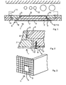
Figur 1- im Schnitt die erfindungsgemäße Revisionsabdeckung als Bestandteil einer feuerbeständigen Wand;
Figur 2- im Schnitt eine Detailansicht der Revisionsabdekkung montiert an einer gefliesten Wand;
Figur 3- perspektivisch eine geflieste Wand mit der erfindungsgemäßen Revisionsabdeckung;
Figur 4- im Schnitt eine weitere Ausführungsform der Revisionsabdeckung;
Figur 5- im Schnitt eine besonders bevorzugte Ausführungsform der Revisionabdeckung;
Figur 6- im Schnitt eine Ausführungsform mit einem Federelement zur Befestigung der Revisionsabdeckung;
Figur 7- im Schnitt eine Ausführungsform mit einem Spreizbügel zur Befestigung der Revisionsabdeckung;
Figur 8- im Schnitt eine Ausführungsform mit Riegelzungen zur Befestigung der Revisionsabdeckung;
Figur 9- im Schnitt eine Ausführungsform mit Klemmbacken zur Befestigung der Revisionsabdeckung;
Figur 10- im Schnitt eine Ausführungsform mit einem schaumartigen Element zur Befestigung der Revisionsabdekkung;
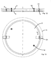
Figur 11- in Rückansicht eine runde Revisionsabdeckung mit zweischichtiger Platte und Abdeckplatte;
Figur 12- im Schnitt eine Ausführungsform mit Bajonettverschluss zur Befestigung der Revisionsabdeckung;
Figur 13- in Draufsicht die Ausführungsform gemäß
Figur 12; Figur 14- im Schnitt eine Ausführungsform mit Riegelmechanismus zur Befestigung der Revisionsabdeckung; und
Figur 15- in Draufsicht die Ausführungsform gemäß
Figur 14.
- FIG. 1
- on average, the revision cover according to the invention as part of a fire-resistant wall;
- FIG. 2
- in section a detail view of the inspection cover mounted on a tiled wall;
- FIG. 3
- in perspective, a tiled wall with the revision cover according to the invention;
- FIG. 4
- in section, another embodiment of the inspection cover;
- FIG. 5
- on average, a particularly preferred embodiment of the revision cover;
- FIG. 6
- in section an embodiment with a spring element for fixing the inspection cover;
- FIG. 7
- in section an embodiment with a Spreizbügel for attaching the inspection cover;
- FIG. 8
- in section, an embodiment with locking tongues for fixing the inspection cover;
- FIG. 9
- in section, an embodiment with clamping jaws for attachment of the inspection cover;
- FIG. 10
- in section, an embodiment with a foam-like element for fixing the Revisionabdekkung;
- FIG. 11
- in rear view a round inspection cover with two-layered plate and cover plate;
- FIG. 12
- in section an embodiment with bayonet lock for attaching the inspection cover;
- FIG. 13
- in plan view, the embodiment of Figure 12;
- FIG. 14
- in section an embodiment with locking mechanism for attaching the inspection cover; and
- FIG. 15
- in plan view, the embodiment of Figure 14.
Die jeweils in den Figuren 1 bis 15 dargestellte Revisionsabdeckung zum Verschluss einer Revisionsöffnung 1 an Wänden und Decken besteht im allgemeinen aus einer ebenen, nicht brennbare Platte 2, die bis auf einen im Randbereich der Revisionsöffnung 1 verbleibenden Spalt 3 passgenau zu dieser ausgebildet ist. Dabei ist vorzugsweise, aber nicht zwingend, im Spalt 3 ein im Brandfall aufschäumender Dämmschichtbildner 4, vorzugsweise sogenanntes Blähgraphit oder ein anderes Intumeszenzmaterial, angeordnet. Der Dämmschichtbildner 4 kann dabei wahlweise am Rand der Revisionsöffnung 1 oder an der Revisionsabdeckung angeordnet sein (siehe insbesondere Figuren 1, 2 und 5).The inspection cover shown in each of FIGS. 1 to 15 for closing an
Wesentlich für alle dargestellten Revisionsabdeckungen ist nun, dass an der bei einer Ausführungsform bevorzugt als vorgefertigtes Bauteil ausgebildeten Platte 2 sichtseitig (d. h. abgewandt vom abzutrennenden Revisionsraum) eine den Spalt 3 überdeckende, vorgefertigte und vorzugsweise aus Metall oder Kunststoff bestehende Abdeckplatte 5 angeordnet und die Platte 2 rahmenlos in die Revisionsöffnung 1 einsetz- und mittels der Befestigungselemente 14, vorzugsweise Schrauben 9, an deren Rand 6 befestigbar ausgebildet ist.It is essential for all illustrated inspection covers that on the preferred in one embodiment as
Mit Bezug auf die Figuren 1, 2, 5 und 11 ist dabei vorteilhaft vorgesehen, dass die Platte 2 mindestens aus zwei zueinander abgestuften Schichten 7, 8 besteht und dass der Rand 6 der Revisionsöffnung 1 zum formschlüssigen Einsatz der Abdeckung entsprechend stufig ausgebildet ist. Dem entsprechend weist auch der Spalt 3 bei zwei- oder mehrschichtiger Ausbildung der Platte 2 einen stufigen Verlauf auf. Dies ist einerseits bezüglich des Brandschutzes vorteilhaft (verbesserte Abdichtung), andererseits entspricht dies vorteilhaft auch der üblichen Aufbauweise von feuerbeständigen Wänden, die nämlich regelmäßig aus zwei zueinander versetzt montierten Schichten bestehen.With reference to FIGS. 1, 2, 5 and 11, it is advantageously provided that the
Ferner ist vorzugsweise, wie in Figur 5 dargestellt, vorgesehen, dass zwischen den Schichten 7, 8 mehrere, vorzugsweise metallische Platten 19 angeordnet sind, die zum kraftschlüssigen Verbund der Schichten 7, 8 beidseitig mit die Schichten 7, 8 durchdringenden Schrauben 20 verbunden sind, wobei zur Abstützung der Schrauben 20 auf der der vorzugsweise metallischen Abdeckplatte 5 abgewandten Seite der Revisionsabdeckung 1 weitere, vorzugsweise ebenfalls metallische Platten 21 angeordnet sind.Furthermore, it is preferably provided, as shown in FIG. 5, that several, preferably metallic, plates 19 are arranged between the
Bezüglich der Platte 2 ist ferner vorteilhaft vorgesehen, dass diese aus nicht brennbarem Material wie Kalziumsilikat und Kalziumsulfat besteht und mindestens 20 mm dick ausgebildet ist. Der Spalt 3 weist in diesem Fall vorzugsweise eine Breite von etwa 1 bis 8 mm auf. Wird die Revisionsöffnung vorort in die Trennwand eingebracht, kann dies beispielsweise mit einer Stich- oder Kreissäge oder einem Kreisschneider (bei runden Revisionsabdeckungen) geschehen. In diesem Fall wird der Rand der Revisionsöffnung regelmäßig nicht stufig ausgebildet sein (siehe beispielsweise Figur 12 und 14).With respect to the
Zur Befestigung der Revisionsabdeckung ist, wie besonders deutlich in Figur 2 dargestellt, vorgesehen, dass die Platte 2 mit Schrauben 9 am Rand 6 der Revisionsöffnung 1 befestigt ist. Dabei sind am Rand der Abdeckplatte 5 Durchgriffsöffnungen 13 für die Schrauben 9 eingebracht.For fastening the inspection cover is, as shown particularly clearly in Figure 2, provided that the
Ferner ist vorzugsweise vorgesehen (siehe Figur 5), dass die Befestigungselemente bzw. Schrauben 9 mit am Rand der Revisionsöffnung 1 angeordneten Klammern 17 in Eingriff bringbar sind, wobei die Klammern 17 den Rand der Revisionsöffnung 1 u-förmig umgreifen und an diesem vorzugsweise mit Schrauben 18 befestigt sind.Furthermore, it is preferably provided (see FIG. 5) that the fastening elements or
Zur Berücksichtigung baulicher Toleranzen ist ferner vorteilhaft vorgesehen, dass die Schrauben 9 zur Befestigung der Revisionsabdeckung lang genug ausgebildet sind, um Distanzänderungen der Abdeckplatte 5 zum Rand 6 der Revisionsöffnung 1 beispielsweise durch dort aufgebrachte Fliesen 10 ausgleichen zu können (siehe Figur 2).In order to take into account structural tolerances, it is furthermore advantageously provided that the
Bezüglich der Abdeckplatte 5 ist vorteilhaft vorgesehen, dass diese den Spalt 3 mindestens um 20 mm überragt und genau wie die Platte 2 eine rechteckige, vorzugsweise quadratische Grundfläche mit den Maßen von 300 mm x 300 mm bis 900 mm x 900 mm aufweist. Alternativ kann die Revisionsöffnung und -abdeckung aber auch rund ausgebildet sein (siehe hierzu insbesondere die Figur 11, 13 und 15) und einen freien Eingriffsdurchmesser von 50 mm (steckdosenartig) bis 900 mm aufweisen. Aus Korrosionsgründen besteht die Abdeckplatte 5 dabei wahlweise vorzugsweise aus Metall (insbesondere Edelstahl) oder Kunststoff (insbesondere bei Deckenrevisionsöffnungen, bei denen die Befestigungselemente nicht direkt an der Abdeckplatte angreifen) und kann aus optischen Gründen, wie in Figur 4 dargestellt, an ihren Rändern einen zum Rand der Revisionsöffnung 1 hin abgekanteten Bereich aufweisen.With respect to the
Der technische Vorteil der erfindungsgemäßen Revisionsabdekkung wird besonders deutlich, wenn man den Montagevorgang einer feuerbeständigen Trennwand mit Revisionsabdeckung betrachtet:The technical advantage of the invention Revisionsabdekkung is particularly clear when the assembly process of a fire-resistant partition with revision cover considered:
Zur feuerhemmenden bzw. feuerbeständigen Abdeckung von Rohren und Leitungen 12 (siehe Figur 1) werden zunächst vor einer Wand (oder Decke) u-förmige Schienen 11 senkrecht aufgestellt (bzw. waagerecht aufgehängt). An diesen wird eine erste Lage nicht brennbarer Platten befestigt.For fire-retardant or fire-resistant covering of pipes and conduits 12 (see FIG. 1),
Bei einer bevorzugten Ausführungsform mit vorgefertigem Rahmen 15, der in seinem Aufbau genau wie die Trennwand selbst ausgebildet ist, wird dieser an der gewünschten Stelle und in Fortsetzung der Trennwandplatten an den Schienen 11 befestigt. Nach dieser ersten Aufbauphase besteht die Trennwand somit aus einer ersten Schicht mit einer Revisionsöffnung, die aus einem vorgefertigen, zweischichtigen Rahmen 15 gebildet ist. Da die zweite Schicht des vorzugsweise an die Ständerkonstruktion größenangepassten Rahmens 15 stufig zur ersten angeordnet ist, kann nun die zweite Schicht der Trennwand vorteilhaft mit Versatz aufgebracht werden. In die am vorgefertigen Rahmen 15 vorgesehene Revisionsöffnung kann schließlich die ebenfalls vorzugsweise zweischichtige, abgestuft ausgebildete Revisionsabdeckung eingesetzt werden.In a preferred embodiment with
Bei einer anderen bevorzugten Ausführungsform (siehe Figur 6 bis 15) wird zunächst die zweite Trennwandschicht mit Versatz aufgebracht. Anschließend wird beispielsweise mit einer Sticksäge oder Kreisschneider eine Öffnung in die Wand oder Decke eingebracht, wobei der ausgeschnittene Teil um die Abdeckplatte 5 und geeignete Befestigungselemente 14 ergänzt als erfindungsgemäße Revisionsabdeckung Verwendung findet. In diesem Fall ist der Rand der Revisionsöffnung aufgrund der Schneidebearbeitung zwar nicht stufig ausgebildet, die erforderliche Abdichtfunktion wird aber auch mittels der Abdeckplatte 5 und im Spalt 3 angeordnetem Dämmschichtbildner 4 gewährleistet.In another preferred embodiment (see FIGS. 6 to 15), the second partition wall layer is first applied with offset. Subsequently, for example, with an embroidery saw or circle cutter an opening in the wall or ceiling is introduced, wherein the cut-out part to the
Die Ausführungsform gemäß Figur 6 zeichnet sich dadurch aus, dass ein an der Platte 2 angeordnetes Federelement 22, vorzugsweise eine ebene Stahlblattfeder, als Befestigungselement 14 vorgesehen ist (wahlweise - nicht dargestellt - auch ergänzend zu anderen Befestigungselementen 14), das den Rand der Revisionsöffnung 1 auf der der Abdeckplatte 5 abgewandten Seite hintergreift und die Revisionsabdeckung auf diese Weise in der Revisionsöffnung 1 fixiert. Zum Fixieren und auch Lösen des Federelements 22 ist darüber hinaus vorgesehen, dass dieses mittels mindestens eines Schraubenelements 23 (schematisch dargestellt) an der Revisionsabdeckung befestigt und dieses die Platte 2 und die Abdeckplatte 5 durchgreifend zugangsseitig (d. h. sichtseitig bzw. abgewandt vom abgetrennten Raum) betätig- und lösbar ausgebildet ist. Da das Federelement 22 bei einem Brand unter Umständen seine Elastizität bzw. Haltekraft verlieren könnte, ist zu dessen Unterstützung im Bereich des Randes 6 der Revisionsöffnung 1 der Dämmschichtbildner 4 zwischen dem Federelement 22 und der Platte 2 angeordnet ist.The embodiment according to FIG. 6 is characterized in that a
Bei der Ausführungsform gemäß Figur 7 ist das Befestigungselement 14 als Spreizbügel 24 ausgebildet, der den Rand der Revisionsöffnung 1 auf der der Abdeckplatte 5 abgewandten Seite hintergreift und die Revisionsabdeckung auf diese Weise in der Revisionsöffnung 1 fixiert. Dabei ist der Spreizbügel 24 mittels mindestens eines Schraubenelements 25 an der Revisionsabdeckung befestigt, wobei dieses die Platte 2 und die Abdeckplatte 5 durchgreifend zugangsseitig betätig- und lösbar ausgebildet ist.In the embodiment according to FIG. 7, the
Bei der Ausführungsform gemäß Figur 8 sind die Befestigungselemente 14 als den der Abdeckplatte 5 abgewandten Rand 6 der Revisionsöffnung 1 hintergreifende verdrehbare Riegelzungen 26 ausgebildet, deren Drehachsen 30 als Stellglieder die Platte 2 und die Abdeckplatte 5 durchgreifen und zugangsseitig betätig- und drehbar sind.In the embodiment according to Figure 8, the
Eine weitere Ausführungsform ist in Figur 9 dargestellt. Bei dieser ist vorgesehen, dass die Befestigungselemente 14 als mit dem Rand 6 der Revisionsöffnung 1 verklemmbare Backen 27 ausgebildet und die Backen 27 über einen zugangsseitig bedienbaren Stellmechanismus 28 betätigbar sind.Another embodiment is shown in FIG. In this case, it is provided that the
Ferner ist bei einer weiteren Ausführungsform gemäß Figur 10 vorgesehen, dass das Befestigungselement 14 als den der Abdeckplatte 5 abgewandten Rand 6 der Revisionsöffnung 1 hintergreifendes, weiches, nachgiebiges, schaumartiges Material 29, beispielsweise Brandschutzschaum, ausgebildet ist, das einerseits stabil genug ist, die Abdeckung in der Öffnung zu halten, andererseits aber auch genug Elastizität aufweist, um die Abdeckung im Bedarfsfall aus der Öffnung herausnehmen zu können.Furthermore, it is provided in a further embodiment according to Figure 10, that the
In den Figuren 12 bis 15 sind schließlich zwei weitere Ausführungsformen dargestellt, nämlich runde Revisionsabdeckungen für beispielsweise an Decken vorgesehene Revisionsöffnungen. Die erste Ausführungsform gemäß Figur 12 und 13 zeichnet sich dadurch aus, dass ein drehbarer Bajonettverschluss 31 zur Fixierung der Revisionsabdeckung in der Revisionsöffnung dient. Die Bauteile des Bajonettverschlusses 31 und die Abdeckplatte 5 werden vorort an den ausgeschnittenen Plattenelementen fixiert.Finally, two further embodiments are shown in FIGS. 12 to 15, namely round inspection covers for inspection openings provided, for example, on ceilings. The first embodiment according to FIGS. 12 and 13 is characterized in that a
Bei der Ausführungsform gemäß Figur 14 und 15 ist ein Riegelmechanismus 32 mit axial verschieblichen Riegelzungen vorgesehen, wie er beispielsweise von Kleiderschränken bekannt ist. Die Betätigung erfolgt über ein nicht dargestelltes, abdeckplattenseitig angeordnetes Stellglied. Die von den Riegelzungen hintergriffenen, zwischen zwei Plattenschichten angeordneten Winkelbleche. 33 werden wie der gesamte Riegelmechanismus vorort montiert.In the embodiment according to FIGS. 14 and 15, a
- 11
- Revisionsöffnunginspection opening
- 22
- Platteplate
- 33
- Spaltgap
- 44
- Dämmschichtbildnerintumescent
- 55
- Abdeckplattecover
- 66
- Randedge
- 77
- Schichtlayer
- 88th
- Schichtlayer
- 99
- Schraubescrew
- 1010
- Fliesetile
- 1111
- Profilschienerail
- 1212
- Rohre, LeitungenPipes, pipes
- 1313
- DurchgriffsöffnungThrough opening
- 1414
- Befestigungselementfastener
- 1515
- Rahmenframe
- 1616
- Versatzoffset
- 1717
- Klammerclip
- 1818
- Schraubescrew
- 1919
- Platteplate
- 2020
- Schraubescrew
- 2121
- Platteplate
- 2222
- Federelementspring element
- 2323
- Schraubenelementscrew element
- 2424
- Spreizbügelspreader
- 2525
- Schraubenelementscrew element
- 2626
- Riegelzungebolt tongue
- 2727
- Backento bake
- 2828
- Stellmechanismusmechanism
- 2929
- schaumartiges Materialfoamy material
- 3030
- Drehachseaxis of rotation
- 3131
- Bajonettverschlussbayonet catch
- 3232
- Riegelmechanismuslocking mechanism
- 3333
- WinkelblechWinkelblech
Claims (10)
dadurch gekennzeichnet,
dass an der Platte (2) sichtseitig eine mindestens den Spalt (3) überdeckende, vorgefertigte Abdeckplatte (5) angeordnet und die Platte (2) rahmenlos in die Revisionsöffnung (1) einsetz- und mittels Befestigungselementen (14) an deren Rand (6) befestigbar ausgebildet ist.Inspection cover for closing an inspection opening (1) on walls, ceilings, shafts, installation or ventilation channels, comprising a flat, non-combustible material consisting of plate (2), except for a remaining gap in the edge region of the access opening (1) (3) is designed precisely to this,
characterized,
that on the plate (2) on the visible side a at least the gap (3) covering, prefabricated cover plate (5) arranged and the plate (2) frameless insertion into the inspection opening (1) and by means of fastening elements (14) at the edge (6) is formed fastened.
dadurch gekennzeichnet,
dass die Abdeckplatte (5) wahlweise aus Metall, vorzugsweise aus Edelstahl, oder Kunststoff besteht,
wobei vorzugsweise die Platte (2) als vorgefertigtes Bauteil ausgebildet ist,
wobei vorzugsweise die Platte (2) und die Abdeckplatte (5) miteinander verklebt sind.Inspection cover according to claim 1,
characterized,
is that the cover plate (5), optionally of metal, preferably of stainless steel or plastic,
wherein preferably the plate (2) is designed as a prefabricated component,
wherein preferably the plate (2) and the cover plate (5) are glued together.
dadurch gekennzeichnet,
dass im Spalt (3) ein im Brandfall aufschäumender Dämmschichtbildner (4) angeordnet ist,
wobei vorzugsweise der Dämmschichtbildner (4) aus Blähgraphit bzw. einem Intumeszenzmaterial besteht,
wobei vorzugsweise die Abdeckplatte (5) den Spalt (3) mindestens um 20 mm überragt,
wobei vorzugsweise die Abdeckplatte (5) an ihren Rändern einen zum Rand der Revisionsöffnung (1) hin abgekanteten Bereich aufweist.Inspection cover according to claim 1 or 2,
characterized,
that in the gap (3) an intumescent layer-forming agent (4), which foams in case of fire, is arranged,
wherein preferably the insulating layer-forming agent (4) consists of expandable graphite or an intumescent material,
wherein preferably the cover plate (5) projects beyond the gap (3) by at least 20 mm,
wherein preferably the cover plate (5) has at its edges a to the edge of the inspection opening (1) bent down area.
dadurch gekennzeichnet,
dass die Platte (2) mindestens aus zwei zueinander abgestuften Schichten (7, 8) besteht und dass der Rand (6) der Revisionsöffnung (1) zum formschlüssigen Einsatz der Abdeckung entsprechend stufig ausgebildet ist,
wobei vorzugsweise zwischen den Schichten (7, 8) mehrere, vorzugsweise metallische Platten (19) angeordnet sind, die zum kraftschlüssigen Verbund der Schichten (7, 8) beidseitig mit die Schichten (7, 8) durchdringenden Schrauben (20) verbunden sind,
wobei vorzugsweise zur Abstützung der Schrauben (20) auf der der Abdeckplatte (5) abgewandten Seite der Revisionsabdeckung (1) weitere, vorzugsweise ebenfalls metallische Platten (21) angeordnet sind,
wobei vorzugsweise bei zwei- oder mehrschichtiger Ausbildung der Platte (2) der Spalt (3) einen stufigen Verlauf aufweist.Inspection cover according to one of claims 1 to 3,
characterized,
in that the plate (2) consists of at least two layers (7, 8) which are graduated from one another and that the edge (6) of the inspection opening (1) is designed in a correspondingly stepped manner for the positive insertion of the cover.
wherein preferably between the layers (7, 8) several, preferably metallic plates (19) are arranged, which are connected to the non-positive connection of the layers (7, 8) on both sides with the layers (7, 8) penetrating screws (20),
wherein preferably for supporting the screws (20) on the cover plate (5) facing away from the inspection cover (1) further, preferably also metallic plates (21) are arranged,
wherein preferably in two- or multi-layered design of the plate (2), the gap (3) has a stepped course.
dadurch gekennzeichnet,
dass die Platte (2) mit Befestigungselementen (14), insbesondere Schrauben (9), am Rand (6) der Revisionsöffnung (1) befestigbar ausgebildet ist,
wobei vorzugsweise am Rand der Abdeckplatte (5) Durchgriffsöffnungen (13) für die Schrauben (9) vorgesehen sind,
wobei vorzugsweise die Schrauben (9) lang genug ausgebildet sind, um Distanzänderungen der Abdeckplatte (5) zum Rand (6) der Revisionsöffnung (1) beispielsweise durch dort aufgebrachte Fliesen ausgleichen zu können,
wobei vorzugsweise die Befestigungselemente (14) bzw. Schrauben (9) mit am Rand der Revisionsöffnung (1) angeordneten Klammern (17) in Eingriff bringbar sind,
wobei vorzugsweise die Klammern (17) den Rand der Revisionsöffnung (1) u-förmig umgreifen und an diesem vorzugsweise mit Schrauben (18) befestigt sind.Inspection cover according to one of claims 1 to 4,
characterized,
in that the plate (2) can be fastened with fastening elements (14), in particular screws (9), on the edge (6) of the inspection opening (1),
wherein preferably at the edge of the cover plate (5) through openings (13) are provided for the screws (9),
wherein preferably the screws (9) are long enough to compensate for changes in distance of the cover plate (5) to the edge (6) of the inspection opening (1), for example by tiles applied there,
wherein preferably the fastening elements (14) or screws (9) can be brought into engagement with clamps (17) arranged on the edge of the inspection opening (1),
wherein preferably the brackets (17) engage around the edge of the inspection opening (1) in a U-shape and are fastened thereto, preferably with screws (18).
dadurch gekennzeichnet,
dass die Platte (2) aus nicht brennbarem Material wie Kalziumsilikat und Kalziumsulfat (Gips) besteht,
wobei die Platte (2) vorzugsweise mindestens 20 mm dick und der Spalt (3) etwa 1 bis 8 mm breit ist.Inspection cover according to one of claims 1 to 5,
characterized,
that the plate (2) consists of non-combustible material such as calcium silicate and calcium sulfate (gypsum),
wherein the plate (2) is preferably at least 20 mm thick and the gap (3) about 1 to 8 mm wide.
dadurch gekennzeichnet,
dass sowohl die Platte (2) als auch die Abdeckplatte (5) eine rechteckige Grundfläche aufweisen,
wobei vorzugsweise die Abdeckplatte (5) wahlweise eine Grundfläche von 300 mm x 300 mm bis 900 mm x 900 mm aufweist.Inspection cover according to one of claims 1 to 6,
characterized,
that both the plate (2) and the cover plate (5) have a rectangular base,
wherein preferably the cover plate (5) optionally has a footprint of 300 mm x 300 mm to 900 mm x 900 mm.
dadurch gekennzeichnet,
dass die Revisionsöffnung (1) einen freien Durchmesser von etwa 50 mm bis 900 mm aufweist,
wobei vorzugsweise die Revisionsöffnung (1) rund und die Revisionsabdeckung entsprechend ausgebildet ist.Inspection cover according to one of claims 1 to 7,
characterized,
that the inspection opening (1) has a free diameter of about 50 mm to 900 mm,
wherein preferably the inspection opening (1) is round and the inspection cover is designed accordingly.
dadurch gekennzeichnet,
dass die Revisionsabdeckung in einer Revisionsöffnung (1) angeordnet ist, die als vorgefertigter, trennwandgleicher Rahmen (15) mit umlaufendem Versatz (16) zum Anbau weiterer Wandelemente ausgebildet ist,
wobei vorzugsweise der Rahmen (15) zu einer vorzugsweise aus Profilschinen (11) bestehenden Ständerkonstruktion einer mindestens feuerhemmenden Trennwand größenangepasst ausgebildet ist.Inspection cover according to one of claims 1 to 8,
characterized,
is arranged that the inspection cover in an inspection opening (1), which is designed as a prefabricated, partition the same frame (15) with circumferential offset (16) for attaching additional wall elements,
wherein preferably the frame (15) to a preferably made of profile rails (11) existing stator construction of an at least fire-retardant partition wall sized adapted.
dadurch gekennzeichnet,
dass das Befestigungselement (14) als drehbarer Bajonettverschluss (31) ausgebildet ist,
oder
dass ein an der Platte (2) angeordnetes Federelement (22), vorzugsweise Stahlfeder, wahlweise als oder auch ergänzend zum Befestigungselement (14) vorgesehen ist, das den Rand der Revisionsöffnung (1) auf der der Abdeckplatte (5) abgewandten Seite hintergreift und die Revisionsabdeckung auf diese Weise in der Revisionsöffnung (1) fixiert,
wobei vorzugsweise das Federelement (22) mittels mindestens eines Schraubenelements (23) an der Revisionsabdeckung befestigt und dieses die Platte (2) und die Abdeckplatte (5) durchgreifend zugangsseitig betätig- und lösbar ausgebildet ist,
wobei vorzugsweise im Bereich des Randes (6) der Revisionsöffnung (1) der Dämmschichtbildner (4) zwischen dem Federelement (22) und der Platte (2) angeordnet ist,
oder
dass das Befestigungselement (14) als Spreizbügel (24) ausgebildet ist, der den Rand der Revisionsöffnung (1) auf der der Abdeckplatte (5) abgewandten Seite hintergreift und die Revisionsabdeckung auf diese Weise in der Revisionsöffnung (1) fixiert,
wobei vorzugsweise der Spreizbügel (24) mittels mindestens eines Schraubenelements (25) an der Revisionsabdeckung befestigt und dieses die Platte (2) und die Abdeckplatte (5) durchgreifend zugangsseitig betätig- und lösbar ausgebildet ist,
oder
dass die Befestigungselemente (14) als den der Abdeckplatte (5) abgewandten Rand (6) der Revisionsöffnung (1) hintergreifende verdrehbare Riegelzungen (26) ausgebildet sind, deren Drehachsen (30) als Stellglieder die Platte (2) und die Abdeckplatte (5) durchgreifen und zugangsseitig betätig- und drehbar ausgebildet sind,
oder
dass die Befestigungselemente (14) als mit dem Rand (6) der Revisionsöffnung (1) verklemmbare Backen (27) ausgebildet sind,
wobei vorzugsweise die Backen (27) über einen zugangsseitig bedienbaren Stellmechanismus (28) betätigbar sind,
oder
dass das Befestigungselement (14) als den der Abdeckplatte (5) abgewandten Rand (6) der Revisionsöffnung (1) hintergreifendes, weiches, nachgiebiges, schaumartiges Material (29) ausgebildet ist,
oder
dass das Befestigungselement (14) als Riegelmechanismus (32) ausgebildet ist, dessen Riegelzungen im Verschlusszustand zwischen Trennwandplatten angeordnete Winkelbleche (33) formschlüssig hintergreifen.Inspection cover according to one of claims 1 to 9,
characterized,
is that the fastening element (14) is formed as a rotatable bayonet lock (31),
or
in that a spring element (22), preferably a steel spring, arranged on the plate (2) is provided optionally as or also in addition to the fastening element (14), which engages behind the edge of the inspection opening (1) on the side facing away from the cover plate (5) and which Inspection cover fixed in this way in the inspection opening (1),
wherein preferably the spring element (22) by means of at least one screw member (23) attached to the inspection cover and this the plate (2) and the cover plate (5) by pressing on the access side and releasably formed,
wherein preferably in the region of the edge (6) of the inspection opening (1) of the intumescent (4) between the spring element (22) and the plate (2) is arranged,
or
is constructed that the fastener (14) as a spreader bar (24) of the edge of the inspection opening (1) on which the cover plate (5) engages behind the side facing away from and fixes the inspection cover in this way, in the inspection opening (1),
wherein preferably the Spreizbügel (24) by means of at least one screw member (25) attached to the inspection cover and this the plate (2) and the cover plate (5) by pressing on the access side and releasably formed,
or
in that the fastening elements (14) are designed as rotatable locking tongues (26) which engage behind the edge (6) of the access opening (1) and face away from the cover plate (5) whose axes of rotation (30) serve as actuators the plate (2) and the cover plate (5). reach through and access side operated and are rotatable,
or
are formed with the edge (6) of the inspection opening (1) verklemmbare jaws (27) and that the fastening elements (14),
wherein preferably the jaws (27) can be actuated via an actuating mechanism (28) which can be operated on the access side,
or
in that the fastening element (14) is designed as a soft, resilient, foam-like material (29) which engages behind the edge (6) of the access opening (1) and faces away from the cover plate (5),
or
in that the fastening element (14) is designed as a locking mechanism (32), the locking tongues of which engage in an interlocking manner behind the locking plates between angle plates (33) arranged between partition plates.
Priority Applications (1)
| Application Number | Priority Date | Filing Date | Title |
|---|---|---|---|
| PL04014700T PL1491702T3 (en) | 2003-06-27 | 2004-06-23 | Inspection cover |
Applications Claiming Priority (4)
| Application Number | Priority Date | Filing Date | Title |
|---|---|---|---|
| DE10329169 | 2003-06-27 | ||
| DE10329169 | 2003-06-27 | ||
| DE10337145A DE10337145A1 (en) | 2003-06-27 | 2003-08-11 | An inspection cover |
| DE10337145 | 2003-08-11 |
Publications (2)
| Publication Number | Publication Date |
|---|---|
| EP1491702A1 true EP1491702A1 (en) | 2004-12-29 |
| EP1491702B1 EP1491702B1 (en) | 2006-09-27 |
Family
ID=33420026
Family Applications (1)
| Application Number | Title | Priority Date | Filing Date |
|---|---|---|---|
| EP04014700A Expired - Lifetime EP1491702B1 (en) | 2003-06-27 | 2004-06-23 | Inspection cover |
Country Status (5)
| Country | Link |
|---|---|
| EP (1) | EP1491702B1 (en) |
| AT (1) | ATE340904T1 (en) |
| DE (1) | DE502004001566D1 (en) |
| ES (1) | ES2274345T3 (en) |
| PL (1) | PL1491702T3 (en) |
Cited By (4)
| Publication number | Priority date | Publication date | Assignee | Title |
|---|---|---|---|---|
| US5941775A (en) * | 1994-10-14 | 1999-08-24 | Sega Of America, Inc. | Data processing system, method thereof and memory cassette |
| EP1911496A3 (en) * | 2006-10-10 | 2009-04-22 | Uta Kamleithner-Maly | Fire protection seal |
| AT512302B1 (en) * | 2012-01-19 | 2013-07-15 | Minka Holz Und Metallverarbeitungs Gmbh | PARTITION WALL OPENING, ESPECIALLY CEILING CLOSURE ORGAN |
| AU2017417515B2 (en) * | 2017-06-08 | 2021-07-01 | Knauf Gips Kg | Device for closing an inspection opening, and method for inserting a device of said type |
Families Citing this family (1)
| Publication number | Priority date | Publication date | Assignee | Title |
|---|---|---|---|---|
| WO2023015201A1 (en) * | 2021-08-04 | 2023-02-09 | Reliance Worldwide Corporation | Fire rated cleanout cover assemblies |
Citations (3)
| Publication number | Priority date | Publication date | Assignee | Title |
|---|---|---|---|---|
| AU519381B3 (en) * | 1981-09-17 | 1982-02-18 | Swan Products Pty. Ltd. | Fireproof cover |
| DE4005128A1 (en) * | 1989-02-22 | 1990-08-23 | Anton Trum Gmbh & Co Kg | Fire resistant inspection opening cover - for walls and ceilings, having swellable sealing strip |
| EP1279779A2 (en) * | 2001-07-27 | 2003-01-29 | Roberto Celli | Plasterboard panel with inspection opening and related closure element |
-
2004
- 2004-06-23 DE DE502004001566T patent/DE502004001566D1/en not_active Expired - Fee Related
- 2004-06-23 AT AT04014700T patent/ATE340904T1/en not_active IP Right Cessation
- 2004-06-23 EP EP04014700A patent/EP1491702B1/en not_active Expired - Lifetime
- 2004-06-23 PL PL04014700T patent/PL1491702T3/en unknown
- 2004-06-23 ES ES04014700T patent/ES2274345T3/en not_active Expired - Lifetime
Patent Citations (3)
| Publication number | Priority date | Publication date | Assignee | Title |
|---|---|---|---|---|
| AU519381B3 (en) * | 1981-09-17 | 1982-02-18 | Swan Products Pty. Ltd. | Fireproof cover |
| DE4005128A1 (en) * | 1989-02-22 | 1990-08-23 | Anton Trum Gmbh & Co Kg | Fire resistant inspection opening cover - for walls and ceilings, having swellable sealing strip |
| EP1279779A2 (en) * | 2001-07-27 | 2003-01-29 | Roberto Celli | Plasterboard panel with inspection opening and related closure element |
Cited By (6)
| Publication number | Priority date | Publication date | Assignee | Title |
|---|---|---|---|---|
| US5941775A (en) * | 1994-10-14 | 1999-08-24 | Sega Of America, Inc. | Data processing system, method thereof and memory cassette |
| EP1911496A3 (en) * | 2006-10-10 | 2009-04-22 | Uta Kamleithner-Maly | Fire protection seal |
| AT512302B1 (en) * | 2012-01-19 | 2013-07-15 | Minka Holz Und Metallverarbeitungs Gmbh | PARTITION WALL OPENING, ESPECIALLY CEILING CLOSURE ORGAN |
| AT512302A4 (en) * | 2012-01-19 | 2013-07-15 | Minka Holz Und Metallverarbeitungs Gmbh | PARTITION WALL OPENING, ESPECIALLY CEILING CLOSURE ORGAN |
| AU2017417515B2 (en) * | 2017-06-08 | 2021-07-01 | Knauf Gips Kg | Device for closing an inspection opening, and method for inserting a device of said type |
| EP3635195B1 (en) * | 2017-06-08 | 2025-04-16 | Knauf Gips KG | Device for closing an inspection opening, and method for inserting a device of said type |
Also Published As
| Publication number | Publication date |
|---|---|
| DE502004001566D1 (en) | 2006-11-09 |
| ES2274345T3 (en) | 2007-05-16 |
| PL1491702T3 (en) | 2007-02-28 |
| ATE340904T1 (en) | 2006-10-15 |
| EP1491702B1 (en) | 2006-09-27 |
Similar Documents
| Publication | Publication Date | Title |
|---|---|---|
| DE20015537U1 (en) | Roof and ceiling system | |
| EP1833133A1 (en) | Mounting device for a cable duct and cable duct | |
| EP2844808B1 (en) | Method for producing a drywall | |
| DE202004019510U1 (en) | Fire protection cabinet for installation equipment in buildings has coated fireproof cable leadthroughs with inner body with supporting material, leadthrough openings with outer fire protection foam coating(s) and outer plate | |
| EP2444562B1 (en) | Safety area | |
| EP1491702B1 (en) | Inspection cover | |
| DE3517836A1 (en) | Closure for an inspection opening | |
| EP2656461B1 (en) | Drywall | |
| DE10011285C2 (en) | Connection profile for ceiling cladding | |
| DE3943165A1 (en) | Wall aperture closer for fire protection around cables, etc. - uses frame fitting into hole and contg. foaming substance inside inner edge that expands to fill mould | |
| EP1705304A2 (en) | Ceiling, wall or floor panel for fire protection purposes | |
| EP1944429A1 (en) | Inspection cover | |
| DE102016125819B4 (en) | Backing device and surrounding frame provided with it | |
| DE102005001622A1 (en) | Framing system fitting around reveal of wall openings for doors or windows, includes sub frame on side facing reveal | |
| DE10337145A1 (en) | An inspection cover | |
| EP1591597B1 (en) | Wall of gypsum wallboard and studs | |
| DE19842512C1 (en) | Arrangement for installing built-in component in wall or hollow body has plate-shaped adapter for insertion into circular opening to adapt cross-section for component to be installed | |
| EP2240651B1 (en) | Profiled strip device | |
| AT408674B (en) | Burglar-resistant stand wall | |
| DE102006054616A1 (en) | Distribution box for use in fire compartment, has housing that is formed of three layers of fire protection plates lying on top of each other, where fire protection plates belonging to middle layer for formation of hollow space have recess | |
| AT524290B1 (en) | Lightweight wall insert for a solid wall | |
| EP0902154A2 (en) | Fireproof glazing | |
| EP4303376A2 (en) | Inspection opening and method for the production of same | |
| DE10112110A1 (en) | Safety and security cabinet has plate construction with protective elements for electrical cables | |
| EP1903162B1 (en) | Inspection device with inspection frame and inspection hatch |
Legal Events
| Date | Code | Title | Description |
|---|---|---|---|
| PUAI | Public reference made under article 153(3) epc to a published international application that has entered the european phase |
Free format text: ORIGINAL CODE: 0009012 |
|
| 17P | Request for examination filed |
Effective date: 20041103 |
|
| AK | Designated contracting states |
Kind code of ref document: A1 Designated state(s): AT BE BG CH CY CZ DE DK EE ES FI FR GB GR HU IE IT LI LU MC NL PL PT RO SE SI SK TR |
|
| AX | Request for extension of the european patent |
Extension state: AL HR LT LV MK |
|
| 17Q | First examination report despatched |
Effective date: 20050203 |
|
| AKX | Designation fees paid |
Designated state(s): AT BE BG CH CY CZ DE DK EE ES FI FR GB GR HU IE IT LI LU MC NL PL PT RO SE SI SK TR |
|
| GRAP | Despatch of communication of intention to grant a patent |
Free format text: ORIGINAL CODE: EPIDOSNIGR1 |
|
| GRAS | Grant fee paid |
Free format text: ORIGINAL CODE: EPIDOSNIGR3 |
|
| GRAA | (expected) grant |
Free format text: ORIGINAL CODE: 0009210 |
|
| AK | Designated contracting states |
Kind code of ref document: B1 Designated state(s): AT BE BG CH CY CZ DE DK EE ES FI FR GB GR HU IE IT LI LU MC NL PL PT RO SE SI SK TR |
|
| PG25 | Lapsed in a contracting state [announced via postgrant information from national office to epo] |
Ref country code: SK Free format text: LAPSE BECAUSE OF FAILURE TO SUBMIT A TRANSLATION OF THE DESCRIPTION OR TO PAY THE FEE WITHIN THE PRESCRIBED TIME-LIMIT Effective date: 20060927 Ref country code: IT Free format text: LAPSE BECAUSE OF FAILURE TO SUBMIT A TRANSLATION OF THE DESCRIPTION OR TO PAY THE FEE WITHIN THE PRESCRIBED TIME-LIMIT;WARNING: LAPSES OF ITALIAN PATENTS WITH EFFECTIVE DATE BEFORE 2007 MAY HAVE OCCURRED AT ANY TIME BEFORE 2007. THE CORRECT EFFECTIVE DATE MAY BE DIFFERENT FROM THE ONE RECORDED. Effective date: 20060927 Ref country code: SI Free format text: LAPSE BECAUSE OF FAILURE TO SUBMIT A TRANSLATION OF THE DESCRIPTION OR TO PAY THE FEE WITHIN THE PRESCRIBED TIME-LIMIT Effective date: 20060927 Ref country code: IE Free format text: LAPSE BECAUSE OF FAILURE TO SUBMIT A TRANSLATION OF THE DESCRIPTION OR TO PAY THE FEE WITHIN THE PRESCRIBED TIME-LIMIT Effective date: 20060927 Ref country code: RO Free format text: LAPSE BECAUSE OF FAILURE TO SUBMIT A TRANSLATION OF THE DESCRIPTION OR TO PAY THE FEE WITHIN THE PRESCRIBED TIME-LIMIT Effective date: 20060927 Ref country code: FI Free format text: LAPSE BECAUSE OF FAILURE TO SUBMIT A TRANSLATION OF THE DESCRIPTION OR TO PAY THE FEE WITHIN THE PRESCRIBED TIME-LIMIT Effective date: 20060927 Ref country code: CZ Free format text: LAPSE BECAUSE OF FAILURE TO SUBMIT A TRANSLATION OF THE DESCRIPTION OR TO PAY THE FEE WITHIN THE PRESCRIBED TIME-LIMIT Effective date: 20060927 |
|
| REG | Reference to a national code |
Ref country code: GB Ref legal event code: FG4D Free format text: NOT ENGLISH |
|
| REG | Reference to a national code |
Ref country code: CH Ref legal event code: EP |
|
| REG | Reference to a national code |
Ref country code: IE Ref legal event code: FG4D Free format text: LANGUAGE OF EP DOCUMENT: GERMAN |
|
| REF | Corresponds to: |
Ref document number: 502004001566 Country of ref document: DE Date of ref document: 20061109 Kind code of ref document: P |
|
| GBT | Gb: translation of ep patent filed (gb section 77(6)(a)/1977) |
Effective date: 20061106 |
|
| PG25 | Lapsed in a contracting state [announced via postgrant information from national office to epo] |
Ref country code: BG Free format text: LAPSE BECAUSE OF FAILURE TO SUBMIT A TRANSLATION OF THE DESCRIPTION OR TO PAY THE FEE WITHIN THE PRESCRIBED TIME-LIMIT Effective date: 20061227 Ref country code: DK Free format text: LAPSE BECAUSE OF FAILURE TO SUBMIT A TRANSLATION OF THE DESCRIPTION OR TO PAY THE FEE WITHIN THE PRESCRIBED TIME-LIMIT Effective date: 20061227 Ref country code: SE Free format text: LAPSE BECAUSE OF FAILURE TO SUBMIT A TRANSLATION OF THE DESCRIPTION OR TO PAY THE FEE WITHIN THE PRESCRIBED TIME-LIMIT Effective date: 20061227 |
|
| REG | Reference to a national code |
Ref country code: CH Ref legal event code: NV Representative=s name: PATENTANWALTSBUERO DR. URS FALK |
|
| REG | Reference to a national code |
Ref country code: PL Ref legal event code: T3 |
|
| PG25 | Lapsed in a contracting state [announced via postgrant information from national office to epo] |
Ref country code: PT Free format text: LAPSE BECAUSE OF FAILURE TO SUBMIT A TRANSLATION OF THE DESCRIPTION OR TO PAY THE FEE WITHIN THE PRESCRIBED TIME-LIMIT Effective date: 20070313 |
|
| ET | Fr: translation filed | ||
| REG | Reference to a national code |
Ref country code: IE Ref legal event code: FD4D |
|
| REG | Reference to a national code |
Ref country code: ES Ref legal event code: FG2A Ref document number: 2274345 Country of ref document: ES Kind code of ref document: T3 |
|
| PLBE | No opposition filed within time limit |
Free format text: ORIGINAL CODE: 0009261 |
|
| STAA | Information on the status of an ep patent application or granted ep patent |
Free format text: STATUS: NO OPPOSITION FILED WITHIN TIME LIMIT |
|
| 26N | No opposition filed |
Effective date: 20070628 |
|
| BERE | Be: lapsed |
Owner name: REUTER, MARTIN Effective date: 20070630 |
|
| PG25 | Lapsed in a contracting state [announced via postgrant information from national office to epo] |
Ref country code: MC Free format text: LAPSE BECAUSE OF NON-PAYMENT OF DUE FEES Effective date: 20070630 |
|
| PG25 | Lapsed in a contracting state [announced via postgrant information from national office to epo] |
Ref country code: BE Free format text: LAPSE BECAUSE OF NON-PAYMENT OF DUE FEES Effective date: 20070630 |
|
| PG25 | Lapsed in a contracting state [announced via postgrant information from national office to epo] |
Ref country code: GR Free format text: LAPSE BECAUSE OF FAILURE TO SUBMIT A TRANSLATION OF THE DESCRIPTION OR TO PAY THE FEE WITHIN THE PRESCRIBED TIME-LIMIT Effective date: 20061228 |
|
| PG25 | Lapsed in a contracting state [announced via postgrant information from national office to epo] |
Ref country code: EE Free format text: LAPSE BECAUSE OF FAILURE TO SUBMIT A TRANSLATION OF THE DESCRIPTION OR TO PAY THE FEE WITHIN THE PRESCRIBED TIME-LIMIT Effective date: 20060927 |
|
| PGRI | Patent reinstated in contracting state [announced from national office to epo] |
Ref country code: IT Effective date: 20080801 |
|
| PGFP | Annual fee paid to national office [announced via postgrant information from national office to epo] |
Ref country code: ES Payment date: 20090623 Year of fee payment: 6 Ref country code: NL Payment date: 20090617 Year of fee payment: 6 |
|
| PG25 | Lapsed in a contracting state [announced via postgrant information from national office to epo] |
Ref country code: CY Free format text: LAPSE BECAUSE OF FAILURE TO SUBMIT A TRANSLATION OF THE DESCRIPTION OR TO PAY THE FEE WITHIN THE PRESCRIBED TIME-LIMIT Effective date: 20060927 Ref country code: LU Free format text: LAPSE BECAUSE OF NON-PAYMENT OF DUE FEES Effective date: 20070623 |
|
| PGFP | Annual fee paid to national office [announced via postgrant information from national office to epo] |
Ref country code: AT Payment date: 20090629 Year of fee payment: 6 Ref country code: PL Payment date: 20090616 Year of fee payment: 6 |
|
| PG25 | Lapsed in a contracting state [announced via postgrant information from national office to epo] |
Ref country code: HU Free format text: LAPSE BECAUSE OF FAILURE TO SUBMIT A TRANSLATION OF THE DESCRIPTION OR TO PAY THE FEE WITHIN THE PRESCRIBED TIME-LIMIT Effective date: 20070328 Ref country code: TR Free format text: LAPSE BECAUSE OF FAILURE TO SUBMIT A TRANSLATION OF THE DESCRIPTION OR TO PAY THE FEE WITHIN THE PRESCRIBED TIME-LIMIT Effective date: 20060927 |
|
| PGFP | Annual fee paid to national office [announced via postgrant information from national office to epo] |
Ref country code: FR Payment date: 20090630 Year of fee payment: 6 |
|
| PGFP | Annual fee paid to national office [announced via postgrant information from national office to epo] |
Ref country code: CH Payment date: 20090923 Year of fee payment: 6 Ref country code: DE Payment date: 20090618 Year of fee payment: 6 Ref country code: GB Payment date: 20090617 Year of fee payment: 6 |
|
| PGFP | Annual fee paid to national office [announced via postgrant information from national office to epo] |
Ref country code: IT Payment date: 20090629 Year of fee payment: 6 |
|
| REG | Reference to a national code |
Ref country code: NL Ref legal event code: V1 Effective date: 20110101 |
|
| REG | Reference to a national code |
Ref country code: CH Ref legal event code: PL |
|
| GBPC | Gb: european patent ceased through non-payment of renewal fee |
Effective date: 20100623 |
|
| REG | Reference to a national code |
Ref country code: FR Ref legal event code: ST Effective date: 20110228 |
|
| PG25 | Lapsed in a contracting state [announced via postgrant information from national office to epo] |
Ref country code: IT Free format text: LAPSE BECAUSE OF NON-PAYMENT OF DUE FEES Effective date: 20100623 |
|
| PG25 | Lapsed in a contracting state [announced via postgrant information from national office to epo] |
Ref country code: CH Free format text: LAPSE BECAUSE OF NON-PAYMENT OF DUE FEES Effective date: 20100630 Ref country code: LI Free format text: LAPSE BECAUSE OF NON-PAYMENT OF DUE FEES Effective date: 20100630 Ref country code: DE Free format text: LAPSE BECAUSE OF NON-PAYMENT OF DUE FEES Effective date: 20110101 |
|
| PG25 | Lapsed in a contracting state [announced via postgrant information from national office to epo] |
Ref country code: AT Free format text: LAPSE BECAUSE OF NON-PAYMENT OF DUE FEES Effective date: 20100623 Ref country code: NL Free format text: LAPSE BECAUSE OF NON-PAYMENT OF DUE FEES Effective date: 20110101 Ref country code: FR Free format text: LAPSE BECAUSE OF NON-PAYMENT OF DUE FEES Effective date: 20100630 |
|
| REG | Reference to a national code |
Ref country code: ES Ref legal event code: FD2A Effective date: 20110715 |
|
| PG25 | Lapsed in a contracting state [announced via postgrant information from national office to epo] |
Ref country code: GB Free format text: LAPSE BECAUSE OF NON-PAYMENT OF DUE FEES Effective date: 20100623 Ref country code: ES Free format text: LAPSE BECAUSE OF NON-PAYMENT OF DUE FEES Effective date: 20110705 |
|
| PG25 | Lapsed in a contracting state [announced via postgrant information from national office to epo] |
Ref country code: ES Free format text: LAPSE BECAUSE OF NON-PAYMENT OF DUE FEES Effective date: 20100624 |
|
| REG | Reference to a national code |
Ref country code: PL Ref legal event code: LAPE |
|
| PG25 | Lapsed in a contracting state [announced via postgrant information from national office to epo] |
Ref country code: PL Free format text: LAPSE BECAUSE OF NON-PAYMENT OF DUE FEES Effective date: 20100623 |