EP1491704B1 - Dispositif étanche pour poignée du couvercle d'une cabine - Google Patents
Dispositif étanche pour poignée du couvercle d'une cabine Download PDFInfo
- Publication number
- EP1491704B1 EP1491704B1 EP20030014284 EP03014284A EP1491704B1 EP 1491704 B1 EP1491704 B1 EP 1491704B1 EP 20030014284 EP20030014284 EP 20030014284 EP 03014284 A EP03014284 A EP 03014284A EP 1491704 B1 EP1491704 B1 EP 1491704B1
- Authority
- EP
- European Patent Office
- Prior art keywords
- hole
- water
- pull rod
- fixed axis
- rod
- Prior art date
- Legal status (The legal status is an assumption and is not a legal conclusion. Google has not performed a legal analysis and makes no representation as to the accuracy of the status listed.)
- Expired - Lifetime
Links
- 230000007306 turnover Effects 0.000 claims description 2
- XLYOFNOQVPJJNP-UHFFFAOYSA-N water Substances O XLYOFNOQVPJJNP-UHFFFAOYSA-N 0.000 description 7
- 230000000694 effects Effects 0.000 description 2
- 238000010276 construction Methods 0.000 description 1
- 230000001419 dependent effect Effects 0.000 description 1
- 239000010410 layer Substances 0.000 description 1
- 238000000034 method Methods 0.000 description 1
- 238000012986 modification Methods 0.000 description 1
- 230000004048 modification Effects 0.000 description 1
- 239000002365 multiple layer Substances 0.000 description 1
- 230000000149 penetrating effect Effects 0.000 description 1
- 238000007789 sealing Methods 0.000 description 1
- 239000007787 solid Substances 0.000 description 1
Images


Classifications
-
- E—FIXED CONSTRUCTIONS
- E05—LOCKS; KEYS; WINDOW OR DOOR FITTINGS; SAFES
- E05B—LOCKS; ACCESSORIES THEREFOR; HANDCUFFS
- E05B17/00—Accessories in connection with locks
- E05B17/002—Weather or dirt protection
-
- E—FIXED CONSTRUCTIONS
- E05—LOCKS; KEYS; WINDOW OR DOOR FITTINGS; SAFES
- E05B—LOCKS; ACCESSORIES THEREFOR; HANDCUFFS
- E05B1/00—Knobs or handles for wings; Knobs, handles, or press buttons for locks or latches on wings
- E05B1/0092—Moving otherwise than only rectilinearly or only rotatively
Definitions
- This invention refers to a pull rod water-proof structure for a cabin cap which utilizes several layers of water-proof rubber rings on the fixing axis of the pull rod main body so that the water is not easily to enter into.
- US-A-4706478 discloses a door lock including a rotary handle, flush mountable, comprising a positioning seat in the form of a pan-shaped housing, which is ordinarily mounted on a closure.
- the lock includes an operating handle or pull rod pivotally connected to a pivot seat of a fixed axis rod.
- the rod has a threaded rearward end region and it extends through an opening or hole formed in a back wall of the positioning seat.
- the rod includes a circumferential extending groove where a spring retaining clip is installed to retain the rod in the positioning seat.
- a pair of washers including a resilient washer or O-ring and a rigid washer are interposed between an upper washer and the back wall.
- the O-ring serves as a weather proof seal.
- the object of this invention is to fabricate a pull rod water-proof structure for a cabin cap which is easily fabricated and with simple construction and which has improved sealing characteristics to thereby increase the usage life. This is achieved by a pull rod water-proof structure for a cabin cap comprising the features of claim 1.
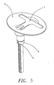
- the water-proof structure of the cabin cap pull rod is mainly comprised of a pull rod main body 1, a positioning seat 2, the ring 4 and the pin 5; said pull rod main body 1 is consisted of a pull rod 11 and a fixed axis rod 12 wherein the pull rod is pivot connected to a pivot seat 121 on the front end of the fixed axis rod 12, on the inner edge of the bottom of the pivot seat 121 there concave settles a first water-proof rubber ring 30, and there settles a second and a third water-proof water-proof rubber ring 31, 32 beneath the first water-proof rubber ring 30 and on the fixed axis rod 12, there settles a screw 122 on the fixed axis rod 12, and there settles a hole 123 on the proper position; on said positioning seat 2 there extends downwardly a stepped hollow positioning column 26 so that it could form a first hole 21 and a second hole 22 wherein the diameter value of the first hole 21 is larger than that of the second hole 22,
- the pivot seat 121 of the pull rod main body 1 is allocated within the first hole 21, wherein the first water-proof rubber ring 30 on the bottom of the pivot seat 121 is pressed on the edge 23 of the second hole 22, meanwhile, the second water-proof rubber ring 31 and the third water-proof rubber ring 32 on the fixed axis rod 12 is allocated within the second hole 22 and is tightly pressed with the inner wall of the second hole 22, meanwhile, by means of the turnover of the pull rod 11, the pull rod could be inserted inside the T typed concave groove 24 of the positioning seat 2, and it positions the fixed axis rod 12 of the pull rod main body 1 and is stably connected with the positioning seat 2 by the ring 4 and the pin 5, by means of the cooperation of the first water-proof rubber ring 30 and the edge 23 of the second hole 22 which could prevent the other water-proof rubber being tired due to long period of usage and further causes a gap such that the water flows into the cabin to achieve better water-proof effects.
Landscapes
- Body Structure For Vehicles (AREA)
- Mechanical Control Devices (AREA)
Claims (3)
- Structure de tige de traction étanche à l'eau pour un couvercle de cabine, comportant :un corps principal de tige de traction (1), qui est constitué d'une tige de traction (11) et d'une tige d'axe fixe (12), dans laquelle un siège de pivotement (121) s'étend depuis le côté supérieur avant de ladite tige d'axe fixe (12), et ladite tige de traction (11) est reliée audit siège de pivotement (121), plusieurs couches d'anneaux en caoutchouc étanches à l'eau (30, 31, 32) étant disposées sur ladite tige d'axe fixe (12) en dessous du siège de pivotement (121), et une vis (122) étant installée sur la tige d'axe fixe (12), dans laquelle la tige d'axe fixe (12) comporte un trou (123) pour relier un anneau (4) à la tige d'axe fixe (12) par l'intermédiaire d'une broche (5) ; etun siège de positionnement (2), dans lequel s'étend vers le bas une colonne de positionnement creuse étagée (26) qui fait que ledit siège de positionnement (2) forme un premier trou (21) et un second trou (22), côte à côte, le bord (23) du second trou (22) faisant saillie vers l'extérieur dans le premier trou (21) pour créer une rainure (25) au fond du premier trou (21) ; où lors d'un montage du corps principal de tige de traction (1) sur le siège de positionnement (2), les étapes suivantes sont effectuées : installation d'un anneau en caoutchouc étanche à l'eau (30) dans une rainure située sur le bord intérieur au fond du siège de pivotement (121) ; insertion de la tige d'axe fixe (12) dans la colonne de positionnement creuse étagée (26), le siège de pivotement (121) étant engagé dans le premier trou (21), l'anneau en caoutchouc étanche à l'eau (30) au fond du siège de pivotement (121) étant comprimé fermement contre le bord supérieur (23) du second trou (22), et connexion de manière stable de la tige d'axe fixe (12) au siège de positionnement (2) en insérant la tige d'axe fixe (12) à travers l'anneau (4), et en la fixant à l'aide de la broche (5).
- Structure de tige de traction étanche à l'eau pour un couvercle de cabine selon la revendication 1, dans laquelle le corps principal de tige de traction (1) est inséré dans la colonne de positionnement creuse étagée (26) du siège de positionnement (2), et dans laquelle un deuxième, et un troisième anneaux en caoutchouc étanches à l'eau (31, 32) sur la tige axiale fixe (12) sont insérés dans le second trou (22), et comprimés fermement contre la paroi intérieure du second trou (22).
- Structure de tige de traction étanche à l'eau pour un couvercle de cabine selon la revendication 1, dans lequel est installée une rainure concave de type T (24) sur ledit siège de positionnement (2), une extrémité de ladite rainure (24) s'interconnectant avec le premier trou (21), ce qui permet d'engager la tige de traction (11) dans la rainure (24) par le basculement de la tige de traction (11).
Priority Applications (1)
| Application Number | Priority Date | Filing Date | Title |
|---|---|---|---|
| EP20030014284 EP1491704B1 (fr) | 2003-06-25 | 2003-06-25 | Dispositif étanche pour poignée du couvercle d'une cabine |
Applications Claiming Priority (1)
| Application Number | Priority Date | Filing Date | Title |
|---|---|---|---|
| EP20030014284 EP1491704B1 (fr) | 2003-06-25 | 2003-06-25 | Dispositif étanche pour poignée du couvercle d'une cabine |
Publications (2)
| Publication Number | Publication Date |
|---|---|
| EP1491704A1 EP1491704A1 (fr) | 2004-12-29 |
| EP1491704B1 true EP1491704B1 (fr) | 2006-11-22 |
Family
ID=33395867
Family Applications (1)
| Application Number | Title | Priority Date | Filing Date |
|---|---|---|---|
| EP20030014284 Expired - Lifetime EP1491704B1 (fr) | 2003-06-25 | 2003-06-25 | Dispositif étanche pour poignée du couvercle d'une cabine |
Country Status (1)
| Country | Link |
|---|---|
| EP (1) | EP1491704B1 (fr) |
Families Citing this family (1)
| Publication number | Priority date | Publication date | Assignee | Title |
|---|---|---|---|---|
| CN116337268B (zh) * | 2021-12-15 | 2025-06-03 | 山东锋火动力通信科技有限公司 | 一种变电站高压开关柜无线无源测温监测设备 |
Family Cites Families (4)
| Publication number | Priority date | Publication date | Assignee | Title |
|---|---|---|---|---|
| US4706478A (en) * | 1986-04-11 | 1987-11-17 | The Eastern Company | Rotary handle operated door lock |
| JPH06264656A (ja) * | 1993-03-16 | 1994-09-20 | Takigen Seizo Kk | 引出し回転型扉用ロックハンドル装置 |
| DE9406584U1 (de) * | 1994-04-20 | 1994-07-28 | Emka Beschlagteile Gmbh & Co. Kg, 42551 Velbert | Verschluß für Schaltschranktüren |
| AU5269500A (en) * | 1999-05-12 | 2000-11-21 | Southco, Inc. | Handle with bumper |
-
2003
- 2003-06-25 EP EP20030014284 patent/EP1491704B1/fr not_active Expired - Lifetime
Also Published As
| Publication number | Publication date |
|---|---|
| EP1491704A1 (fr) | 2004-12-29 |
Similar Documents
| Publication | Publication Date | Title |
|---|---|---|
| RU2010129695A (ru) | Средство фиксации для землеройного органа | |
| US5360253A (en) | Fitting assembly for an air spoiler | |
| US6981286B2 (en) | Hidden mounting of water valve body and headworks assembly | |
| JPH10109603A (ja) | ドアのシール構造を有する自動車 | |
| WO2009132390A1 (fr) | Point de fixation en retrait | |
| CN106143798B (zh) | 埋入式中心快启闭舱口盖 | |
| JPH046247Y2 (fr) | ||
| US12168864B2 (en) | One-piece toilet with flush valve | |
| CN106553592B (zh) | 用于安装车辆的后置摄像头的结构 | |
| CA2371473A1 (fr) | Robinet de lavabo a poignee unique avec collet de centrage du corps du robinet | |
| US20050005403A1 (en) | Water-proof structure of the pull-rod of the cabin cap | |
| US7596819B2 (en) | Trip lever assembly | |
| EP1491704A1 (fr) | Dispositif étanche pour poignée du couvercle d'une cabine | |
| CN215552875U (zh) | 一种后视镜镜面调节器摩擦球窝结构、汽车后视镜和汽车 | |
| US6364286B1 (en) | Manually actuated valve | |
| KR200338278Y1 (ko) | 양변기의 세척수 2단 배수장치 | |
| CN211524379U (zh) | 一种门把手 | |
| CN209785696U (zh) | 一种变压器仪表防雨结构 | |
| CN208778308U (zh) | 一种用于电风扇的安装机构 | |
| CN214888881U (zh) | 一种防烫脸盆龙头 | |
| CN222398031U (zh) | 一种水箱 | |
| CN106585777B (zh) | 一种电动车抗震电瓶锁 | |
| JP2006193923A (ja) | ストレーナ部材の脱着構造 | |
| CN218405680U (zh) | 一种线控下水组件 | |
| US7120944B2 (en) | Gripe mechanism of a reservoir tank for a toilet bowl |
Legal Events
| Date | Code | Title | Description |
|---|---|---|---|
| PUAI | Public reference made under article 153(3) epc to a published international application that has entered the european phase |
Free format text: ORIGINAL CODE: 0009012 |
|
| AK | Designated contracting states |
Kind code of ref document: A1 Designated state(s): AT BE BG CH CY CZ DE DK EE ES FI FR GB GR HU IE IT LI LU MC NL PT RO SE SI SK TR |
|
| AX | Request for extension of the european patent |
Extension state: AL LT LV MK |
|
| 17P | Request for examination filed |
Effective date: 20050209 |
|
| 17Q | First examination report despatched |
Effective date: 20050601 |
|
| AKX | Designation fees paid |
Designated state(s): IT |
|
| REG | Reference to a national code |
Ref country code: DE Ref legal event code: 8566 |
|
| GRAP | Despatch of communication of intention to grant a patent |
Free format text: ORIGINAL CODE: EPIDOSNIGR1 |
|
| GRAS | Grant fee paid |
Free format text: ORIGINAL CODE: EPIDOSNIGR3 |
|
| GRAA | (expected) grant |
Free format text: ORIGINAL CODE: 0009210 |
|
| AK | Designated contracting states |
Kind code of ref document: B1 Designated state(s): IT |
|
| PLBE | No opposition filed within time limit |
Free format text: ORIGINAL CODE: 0009261 |
|
| STAA | Information on the status of an ep patent application or granted ep patent |
Free format text: STATUS: NO OPPOSITION FILED WITHIN TIME LIMIT |
|
| 26N | No opposition filed |
Effective date: 20070823 |
|
| PGFP | Annual fee paid to national office [announced via postgrant information from national office to epo] |
Ref country code: IT Payment date: 20070628 Year of fee payment: 5 |
|
| PG25 | Lapsed in a contracting state [announced via postgrant information from national office to epo] |
Ref country code: IT Free format text: LAPSE BECAUSE OF NON-PAYMENT OF DUE FEES Effective date: 20080625 |