EP1491739A1 - Abgaskrümmer - Google Patents
Abgaskrümmer Download PDFInfo
- Publication number
- EP1491739A1 EP1491739A1 EP20030076917 EP03076917A EP1491739A1 EP 1491739 A1 EP1491739 A1 EP 1491739A1 EP 20030076917 EP20030076917 EP 20030076917 EP 03076917 A EP03076917 A EP 03076917A EP 1491739 A1 EP1491739 A1 EP 1491739A1
- Authority
- EP
- European Patent Office
- Prior art keywords
- coolant
- outlet
- cylinder head
- face
- internal combustion
- Prior art date
- Legal status (The legal status is an assumption and is not a legal conclusion. Google has not performed a legal analysis and makes no representation as to the accuracy of the status listed.)
- Granted
Links
Images


Classifications
-
- F—MECHANICAL ENGINEERING; LIGHTING; HEATING; WEAPONS; BLASTING
- F01—MACHINES OR ENGINES IN GENERAL; ENGINE PLANTS IN GENERAL; STEAM ENGINES
- F01P—COOLING OF MACHINES OR ENGINES IN GENERAL; COOLING OF INTERNAL-COMBUSTION ENGINES
- F01P3/00—Liquid cooling
- F01P3/20—Cooling circuits not specific to a single part of engine or machine
- F01P3/207—Cooling circuits not specific to a single part of engine or machine liquid-to-liquid heat-exchanging relative to marine vessels
-
- F—MECHANICAL ENGINEERING; LIGHTING; HEATING; WEAPONS; BLASTING
- F01—MACHINES OR ENGINES IN GENERAL; ENGINE PLANTS IN GENERAL; STEAM ENGINES
- F01N—GAS-FLOW SILENCERS OR EXHAUST APPARATUS FOR MACHINES OR ENGINES IN GENERAL; GAS-FLOW SILENCERS OR EXHAUST APPARATUS FOR INTERNAL-COMBUSTION ENGINES
- F01N3/00—Exhaust or silencing apparatus having means for purifying, rendering innocuous, or otherwise treating exhaust
- F01N3/02—Exhaust or silencing apparatus having means for purifying, rendering innocuous, or otherwise treating exhaust for cooling, or for removing solid constituents of, exhaust
- F01N3/04—Exhaust or silencing apparatus having means for purifying, rendering innocuous, or otherwise treating exhaust for cooling, or for removing solid constituents of, exhaust using liquids
- F01N3/043—Exhaust or silencing apparatus having means for purifying, rendering innocuous, or otherwise treating exhaust for cooling, or for removing solid constituents of, exhaust using liquids without contact between liquid and exhaust gases
- F01N3/046—Exhaust manifolds with cooling jacket
-
- F—MECHANICAL ENGINEERING; LIGHTING; HEATING; WEAPONS; BLASTING
- F01—MACHINES OR ENGINES IN GENERAL; ENGINE PLANTS IN GENERAL; STEAM ENGINES
- F01P—COOLING OF MACHINES OR ENGINES IN GENERAL; COOLING OF INTERNAL-COMBUSTION ENGINES
- F01P3/00—Liquid cooling
- F01P3/02—Arrangements for cooling cylinders or cylinder heads
-
- F—MECHANICAL ENGINEERING; LIGHTING; HEATING; WEAPONS; BLASTING
- F01—MACHINES OR ENGINES IN GENERAL; ENGINE PLANTS IN GENERAL; STEAM ENGINES
- F01P—COOLING OF MACHINES OR ENGINES IN GENERAL; COOLING OF INTERNAL-COMBUSTION ENGINES
- F01P3/00—Liquid cooling
- F01P3/20—Cooling circuits not specific to a single part of engine or machine
- F01P3/202—Cooling circuits not specific to a single part of engine or machine for outboard marine engines
-
- F—MECHANICAL ENGINEERING; LIGHTING; HEATING; WEAPONS; BLASTING
- F02—COMBUSTION ENGINES; HOT-GAS OR COMBUSTION-PRODUCT ENGINE PLANTS
- F02B—INTERNAL-COMBUSTION PISTON ENGINES; COMBUSTION ENGINES IN GENERAL
- F02B37/00—Engines characterised by provision of pumps driven at least for part of the time by exhaust
-
- F—MECHANICAL ENGINEERING; LIGHTING; HEATING; WEAPONS; BLASTING
- F01—MACHINES OR ENGINES IN GENERAL; ENGINE PLANTS IN GENERAL; STEAM ENGINES
- F01P—COOLING OF MACHINES OR ENGINES IN GENERAL; COOLING OF INTERNAL-COMBUSTION ENGINES
- F01P3/00—Liquid cooling
- F01P3/02—Arrangements for cooling cylinders or cylinder heads
- F01P2003/024—Cooling cylinder heads
-
- F—MECHANICAL ENGINEERING; LIGHTING; HEATING; WEAPONS; BLASTING
- F01—MACHINES OR ENGINES IN GENERAL; ENGINE PLANTS IN GENERAL; STEAM ENGINES
- F01P—COOLING OF MACHINES OR ENGINES IN GENERAL; COOLING OF INTERNAL-COMBUSTION ENGINES
- F01P2060/00—Cooling circuits using auxiliaries
- F01P2060/16—Outlet manifold
-
- F—MECHANICAL ENGINEERING; LIGHTING; HEATING; WEAPONS; BLASTING
- F01—MACHINES OR ENGINES IN GENERAL; ENGINE PLANTS IN GENERAL; STEAM ENGINES
- F01P—COOLING OF MACHINES OR ENGINES IN GENERAL; COOLING OF INTERNAL-COMBUSTION ENGINES
- F01P7/00—Controlling of coolant flow
- F01P7/14—Controlling of coolant flow the coolant being liquid
- F01P7/16—Controlling of coolant flow the coolant being liquid by thermostatic control
-
- Y—GENERAL TAGGING OF NEW TECHNOLOGICAL DEVELOPMENTS; GENERAL TAGGING OF CROSS-SECTIONAL TECHNOLOGIES SPANNING OVER SEVERAL SECTIONS OF THE IPC; TECHNICAL SUBJECTS COVERED BY FORMER USPC CROSS-REFERENCE ART COLLECTIONS [XRACs] AND DIGESTS
- Y02—TECHNOLOGIES OR APPLICATIONS FOR MITIGATION OR ADAPTATION AGAINST CLIMATE CHANGE
- Y02T—CLIMATE CHANGE MITIGATION TECHNOLOGIES RELATED TO TRANSPORTATION
- Y02T10/00—Road transport of goods or passengers
- Y02T10/10—Internal combustion engine [ICE] based vehicles
- Y02T10/12—Improving ICE efficiencies
Definitions
- the invention relates to a cylinder head according to the preamble of claim 1.
- the invention further relates to an internal combustion engine according to the preamble of claim 11.
- the invention relates to a cylinder head having outlet ports connected to a coolant chamber of the cylinder head, which outlet ports are arranged to be connected to inlets arranged on a exhaust manifold cooling jacket.
- Marine propulsion systems are frequently mounted in environments sensitive to excessive heating. For this reason are exhaust manifolds and turbo units frequently connected to a liquid coolant system.
- US 4,977,741 A describes an exhaust system combining an exhaust manifold and exhaust elbow, where the manifold is surrounded by a first water jacket and the elbow by a second water jacket. First and second water jackets are separated by a dam containing a passage for fluid communication between them. This will permit different temperature regions to be established in the exhaust system and prevent the formation of condensate due to excessive cooling of the exhaust gases.
- a cylinder head for a liquid cooled engine normally includes a coolant chamber, which is arranged to cool exhaust channels arranged in the cylinder head.
- the coolant chamber of the cylinder head is provided with inlet openings normally being connected to outlet openings of a coolant chamber arranged in a cylinder block.
- the coolant chamber of the cylinder head further includes outlet ports at which the coolant liquid leaves the cylinder head to coolant ducts arranged outside of the cylinder head.
- the cylinder head is provided with an integral coolant cross over passage providing a first port for connection to a first exhaust manifold cooling jacket outlet and extending between said first port arranged at said lateral exhaust flange face and a first coolant outlet arranged at another of said faces.
- a coolant cross over passage is a return flow duct for coolant liquid.
- the coolant liquid according to the invention has preferably first passed a coolant chamber of the cylinder head, being further directed externally of the cylinder head, preferably to a coolant chamber of a turbo unit, to return via the coolant cross over passage.
- coolant cross over passage is integral is meant that the channel is formed in the die cast block that forms the cylinder head.
- the passage is preferably formed when casting the cylinder head, but could optionally be cut out from the die cast block forming the cylinder head.
- the integral coolant cross over passage according to the invention is arranged to lead the return flow from an exhaust manifold cooling jacket through the cylinder head.
- This construction eliminates the need for arranging return flow conduits, as is done in prior art engine layouts, on top or beside the cylinder head. The invention thereby results in a compact engine design.
- the cylinder head is provided with a preferably integral coolant short-circuiting passage at its first front end, which may connect the cooling jacket to a coolant pump.
- the coolant cross-over passage and a coolant short circuiting passage will depart from the exhaust flange face. Effective cooling of the exhaust manifold is achieved by providing the exhaust flange face preferably for each cylinder with at least one inlet opening into the coolant chamber for fluid communication between the coolant chamber and the cooling jacket.
- the coolant cross-over passage extends to an inlet flange face of an inlet manifold. Even more space will be saved if the coolant short-circuiting passage extends to a cylinder head sealing face sealing a crankcase.
- the integral coolant cross-over passage preferably leads between two opposed longitudinal sides of the cylinder head.
- the cross-over passage links the coolant outlet duct of the exhaust manifold cooling jacket to a coolant outlet duct arranged on an intake flange face arranged to be connected to an intake manifold.
- the integral coolant cross over passage preferably leads to a heat exchanger.
- the cross over passage is provided in the vicinity of front face of the cylinder head.
- the cylinder head according to a preferred embodiment which allow a particularly compact coolant system design is provided with an integral coolant short circuit passage providing a second port for connection to a second exhaust manifold cooling jacket outlet and extending between said second port arranged at said lateral exhaust flange face and a second coolant outlet duct of the cylinder head arranged at another of said faces for connection to a coolant pump inlet.
- the second coolant outlet duct is arranged at a bottom face of the cylinder head.
- the second coolant outlet duct is connected an inlet to a pump housing.
- the cylinder head is particularly well suited for use with marine engines.
- a further object of the invention is to provide an internal combustion engine allowing a compact layout of the coolant system.
- cooling jacket as a main coolant passage collecting the coolant coming in from a coolant chamber arranged in the cylinder head, the cooling jacket communicating with the coolant chamber in the cylinder head via at least one inlet opening per cylinder.
- the cooling jacket is divided by at least one partitioning wall into a coolant inlet duct and a coolant outlet duct.
- the coolant inlet duct is connected to a set of inlets arranged on said exhaust manifold cooling jacket and leads to an outlet opening which is arranged to be connected to an inlet opening to a coolant chamber arranged in a turbo charger assembly.
- the coolant outlet duct of the exhaust manifold cooling jacket extends between an inlet opening and a first outlet of said exhaust manifold cooling jacket.
- the first cooling jacket outlet is arranged to be connected to the first port of the integral coolant cross over passage arranged in the cylinder head and the inlet opening of the coolant outlet duct is arranged to be connected to an outlet opening from a coolant chamber arranged in a turbo assembly.
- the coolant inlet duct and the coolant outlet duct should be flow-connected via at least one bypass opening. Temperature distribution will be even more uniform if at least one bypass opening is provided for each cylinder.
- the proposal is put forward that the coolant inlet duct be disposed above the coolant outlet duct.
- the second coolant passage has a larger flow cross-section than the first coolant passage.
- the exhaust manifold cooling jacket with a seat for heat control valve at which the coolant outlet duct is divided into a first and a second exhaust manifold cooling jacket outlets.
- the valve is designed to guide the coolant stream from the coolant outlet duct of the exhaust manifold cooling jacket to a coolant pump, either directly via an integral coolant short circuit passage arranged in the cylinder head, or indirectly via the coolant cross over passage and a heat exchanger.
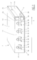
- Figure 1 show a perspective view of a cylinder head 1 according to the invention.
- the cylinder head 1 head has a top face 1a, a bottom face 1b arranged to be connected to a cylinder block, a lateral exhaust flange face 1c arranged to be connected to an exhaust manifold, a second lateral face 1d being opposed to said lateral exhaust flange face 1c, a front face 1e and an end face 1f.
- the cylinder head 1 is provided with an integral coolant cross over passage 2 providing a first port 2a for connection to a first exhaust manifold cooling jacket outlet and extending between said first port 2a arranged at the lateral exhaust flange face 1c and a first coolant outlet 2b arranged at said second lateral face 1 d, which is an inlet flange face arranged to be connected to an intake manifold 7.
- the cylinder head 1 is furthermore provided with an integral coolant short circuit passage 3 providing a second port 3a for connection to a second exhaust manifold cooling jacket outlet and extending between said second port 3a arranged at said lateral exhaust flange face 1c and a second coolant outlet 3b arranged at the bottom face 1 b for connection to a coolant pump inlet.
- the cylinder head is provided with a coolant chamber 23, fig 2 extending along a length axis 4 of the cylinder head 1.
- the coolant chamber 23 is arranged for cooling a plurality of exhaust channels 5a - 5h provided in the cylinder head 1.
- the lateral exhaust flange face 1c is provided with at least one outlet port 6a - 6d for each cylinder in said plurality of exhaust channels 5a - 5h.
- the outlet ports 6a - 6d are connected to said coolant chamber and are arranged to provide connections to a corresponding set of inlets arranged on an exhaust manifold cooling jacket.
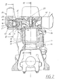
- the figures 2 - 12 show an internal combustion engine 11 in which a cylinder head 1 according to the invention is used.
- the internal combustion engine is provided with several cylinders 12 for reciprocating pistons 13.
- the engine 11 has a cylinder block 14 to which a cylinder head 1 is bolted.
- An exhaust manifold assembly 40 including an exhaust manifold 17 is flanged on to an exhaust flange face 1 c on the side of the cylinder head 1.
- the exhaust manifold 17 is surrounded by a cooling jacket 18.
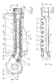
- the cooling jacket 18 is divided by a partitioning wall 19 in the flow direction of the exhaust stream into a coolant inlet duct 20 and a coolant outlet duct 21.
- the exhaust manifold 17 communicates with at least one exhaust port 41 per cylinder 12.
- the coolant inlet duct 20 has a set of inlets 22 including at least one inlet 22a - 22d per cylinder 12, which is flow-connected to the coolant chamber 23 of the cylinder head 1 via the outlet ports 6a - 6d of the cylinder head 1.
- the coolant inlet duct 20 leads from said set of inlets 22 to an outlet opening 20a of said coolant inlet duct.
- the outlet opening 20a of the coolant inlet duct 20 is connected to an inlet opening 27 to a coolant chamber 28 arranged in a turbo charger assembly 26.
- the coolant outlet duct 21 extends between an inlet opening 21a of said coolant outlet duct via a thermostat space 32a at which the coolant outlet duct 21 is branched into a first and a second branch 21b, 21c provided with a first exhaust manifold cooling jacket outlet 21 d and a second exhaust manifold cooling jacket outlet 21e.
- the coolant inlet duct 20 is connected to the coolant outlet duct 21 via at least one bypass opening 24.
- the exhaust manifold assembly 40 extends essentially along a longitudinal side of the cylinder head 1 between a front face 1e and an end face 1f.
- a thermostat space 32a is provided for a heat control valve 32, which takes the coolant stream coming in from the coolant outlet duct 21, either via a coolant cross-over passage 2 situated in the area of the front face 1e of the cylinder head 1 and the coolant outlet duct 35 to the heat exchanger 36 and, further on, to the coolant pump 37, or via a coolant short-circuiting passage 3 directly to the coolant pump 37.
- Fig. 7 shows the position of the control valve sliding sleeve 32b when the engine is warm, Fig. 8 when the engine is cold.
- the exhaust manifold 17 is connected to the turbine part 25 of a water-cooled turbocharger 26 on the side of the second end 30 of the exhaust manifold assembly 40 in the area of the end face 1f of the cylinder head 1.
- the coolant inlet 27 of the coolant chamber 28 of the turbocharger 26 is connected to the first coolant passage 20 of the exhaust manifold 17, the coolant outlet 29 to the second coolant passage 21 of the exhaust manifold 17.
- the coolant flow is indicated schematically by arrows P 1 ,P 1 .
- the coolant will flow from cylinder coolant chambers 39 in the crankcase 14 into coolant chambers 23 in the cylinder head 1, from where it passes through inlets coolant chambers 23 in the cylinder head 1, from where it passes through inlets 22 into the first coolant passage 20, upon which the coolant stream is divided.
- the main stream in the first coolant passage 20, which is marked by full arrows P in Fig. 3, is passed to the turbine part 25 of the turbocharger 26, in the same flow direction as the exhaust gas in the exhaust manifold 17.
- the coolant stream flows through the coolant chambers 28 of the turbine part 25 of the turbocharger 26, and will reach the heat control valve 32 located at the front face 1 e of the cylinder head 1 via the second coolant passage 21, against the flow direction of the exhaust stream.
- Secondary streams of the coolant will reach the second coolant passage 21 directly from the first coolant passage 20, via bypass openings 24. These secondary streams are entered in Fig. 3 by broken arrows P 1 . Secondary streams P 1 are controlled by predefined throttle cross-sections. Throttling may be achieved by providing precisely defined openings 24a (see Fig. 4), in the partitioning wall 19 or by restricted cross-sections 24b formed integral with the bypass openings 24, as shown in Fig. 5. With the aid of the secondary streams P 1 , a uniform temperature distribution will be obtained in the exhaust manifold assembly 40. In addition, excessive cooling of the turbine part 25 of the turbocharger 26 will be prevented.
- the heat control valve 32 will direct the coolant stream P to the coolant pump 37, either directly via a short-circuiting passage 38, or indirectly via a coolant cross-over passage 2. Once a certain, predefined coolant temperature is reached, the heat control valve 32 will open the flow path via the coolant cross-over passage 2 to a heat exchanger 36, in order to ensure sufficient cooling of the coolant. From the heat exchanger 36 the coolant will reach the coolant pump 37.
- the coolant cross-over passage 2 which departs from the exhaust flange face 1c and preferably extends to the inlet flange face 1d of an inlet manifold not shown in the drawings, is positioned at the front face 1e of the cylinder head 1, and, more preferably, cast integral therewith.
- the coolant short-circuiting passage 3 extending between the exhaust flange face 1c and the cylinder head sealing face 1d, is also cast integral with the cylinder head 1.
- the assembly described in this application will permit uniform cooling of the exhaust manifold assembly 40 in a simple and space-saving manner.
Landscapes
- Engineering & Computer Science (AREA)
- Chemical & Material Sciences (AREA)
- Combustion & Propulsion (AREA)
- Mechanical Engineering (AREA)
- General Engineering & Computer Science (AREA)
- Ocean & Marine Engineering (AREA)
- Cylinder Crankcases Of Internal Combustion Engines (AREA)
- Exhaust Silencers (AREA)
- Control Of Throttle Valves Provided In The Intake System Or In The Exhaust System (AREA)
Priority Applications (5)
| Application Number | Priority Date | Filing Date | Title |
|---|---|---|---|
| DE60310539T DE60310539T2 (de) | 2003-06-19 | 2003-06-19 | Abgaskrümmer |
| EP03076917A EP1491739B1 (de) | 2003-06-19 | 2003-06-19 | Abgaskrümmer |
| AT03076917T ATE348948T1 (de) | 2003-06-19 | 2003-06-19 | Abgaskrümmer |
| PCT/SE2004/000914 WO2004111404A1 (en) | 2003-06-19 | 2004-06-11 | Cylinder head and combustion engine comprising a cylinder head |
| US11/306,184 US7430994B2 (en) | 2003-06-19 | 2005-12-19 | Cylinder head and combustion engine comprising a cylinder head |
Applications Claiming Priority (1)
| Application Number | Priority Date | Filing Date | Title |
|---|---|---|---|
| EP03076917A EP1491739B1 (de) | 2003-06-19 | 2003-06-19 | Abgaskrümmer |
Publications (2)
| Publication Number | Publication Date |
|---|---|
| EP1491739A1 true EP1491739A1 (de) | 2004-12-29 |
| EP1491739B1 EP1491739B1 (de) | 2006-12-20 |
Family
ID=33395921
Family Applications (1)
| Application Number | Title | Priority Date | Filing Date |
|---|---|---|---|
| EP03076917A Expired - Lifetime EP1491739B1 (de) | 2003-06-19 | 2003-06-19 | Abgaskrümmer |
Country Status (5)
| Country | Link |
|---|---|
| US (1) | US7430994B2 (de) |
| EP (1) | EP1491739B1 (de) |
| AT (1) | ATE348948T1 (de) |
| DE (1) | DE60310539T2 (de) |
| WO (1) | WO2004111404A1 (de) |
Cited By (3)
| Publication number | Priority date | Publication date | Assignee | Title |
|---|---|---|---|---|
| AT500442B1 (de) * | 2005-07-19 | 2008-06-15 | Avl List Gmbh | Zylinderkopf für eine brennkraftmaschine |
| CN106523121A (zh) * | 2016-10-19 | 2017-03-22 | 盐城工学院 | 船用水冷柴油机海淡水热交换系统及热交换方法 |
| US10954844B2 (en) | 2015-11-11 | 2021-03-23 | Deutz Aktiengesellschaft | Common rail water jacket |
Families Citing this family (13)
| Publication number | Priority date | Publication date | Assignee | Title |
|---|---|---|---|---|
| AT503182B1 (de) * | 2007-04-05 | 2008-10-15 | Avl List Gmbh | Flüssigkeitsgekühlte brennkraftmaschine |
| US8146544B2 (en) * | 2009-03-05 | 2012-04-03 | GM Global Technology Operations LLC | Engine cylinder head cooling features and method of forming |
| US8479691B1 (en) | 2009-05-19 | 2013-07-09 | Brunswick Corporation | Method for cooling a four stroke marine engine with multiple path coolant flow through its cylinder head |
| US8402930B1 (en) | 2009-05-19 | 2013-03-26 | Brunswick Corporation | Method for cooling a four stroke marine engine with increased segregated heat removal from its exhaust manifold |
| US8621865B2 (en) * | 2010-05-04 | 2014-01-07 | Ford Global Technologies, Llc | Internal combustion engine with liquid-cooled turbine |
| DE102010037378A1 (de) * | 2010-09-07 | 2012-03-08 | Ford Global Technologies, Llc | Zylinderkopf mit Turbine |
| US8973538B2 (en) | 2010-06-18 | 2015-03-10 | Caterpillar Inc. | Inline engine having side-mounted heat exchangers |
| US8931441B2 (en) * | 2012-03-14 | 2015-01-13 | Ford Global Technologies, Llc | Engine assembly |
| JP5981830B2 (ja) * | 2012-10-19 | 2016-08-31 | 本田技研工業株式会社 | シリンダヘッドのウォータージャケット構造 |
| US9365274B1 (en) | 2013-11-19 | 2016-06-14 | Brunswick Corporation | Outboard marine propulsion devices having cooling systems |
| DE102015009501A1 (de) * | 2015-07-22 | 2017-01-26 | GM Global Technology Operations LLC (n. d. Ges. d. Staates Delaware) | Brennkraftmaschinenkühlung |
| US9810134B2 (en) * | 2015-08-13 | 2017-11-07 | Ford Global Technologies, Llc | Internal combustion engine cooling system |
| US12253054B1 (en) * | 2023-11-10 | 2025-03-18 | Managed Programs, LLC | Chemically resistant inserts and/or spacers for an intake manifold that enable flow of coolant fluid and kits having the same |
Citations (3)
| Publication number | Priority date | Publication date | Assignee | Title |
|---|---|---|---|---|
| US4187678A (en) * | 1976-04-08 | 1980-02-12 | Perkins Engines Limited | Marine engine manifold |
| US5036804A (en) * | 1989-04-28 | 1991-08-06 | Sanshin Kogyo Kabushiki Kaisha | Cooling system for four stroke outboard motor |
| EP1258613A2 (de) * | 2001-05-15 | 2002-11-20 | Honda Giken Kogyo Kabushiki Kaisha | Aussenbordbrennkraftmaschine |
Family Cites Families (9)
| Publication number | Priority date | Publication date | Assignee | Title |
|---|---|---|---|---|
| US5950425A (en) * | 1996-03-11 | 1999-09-14 | Sanshin Kogyo Kabushiki Kaisha | Exhaust manifold cooling |
| JP3765900B2 (ja) * | 1997-02-03 | 2006-04-12 | 本田技研工業株式会社 | 船外機用エンジンの冷却装置 |
| JP3630004B2 (ja) * | 1999-03-11 | 2005-03-16 | スズキ株式会社 | 船外機の排気通路構造 |
| JP3695232B2 (ja) * | 1999-07-14 | 2005-09-14 | スズキ株式会社 | 船外機の排気装置 |
| JP4271362B2 (ja) * | 2000-06-28 | 2009-06-03 | ヤマハ発動機株式会社 | 船外機用4サイクルエンジンの排気装置 |
| JP3775572B2 (ja) * | 2001-05-17 | 2006-05-17 | 本田技研工業株式会社 | 水冷式内燃機関 |
| JP2003002295A (ja) * | 2001-06-19 | 2003-01-08 | Sanshin Ind Co Ltd | 船外機の冷却構造 |
| JP2004132307A (ja) * | 2002-10-11 | 2004-04-30 | Honda Motor Co Ltd | 水冷バーチカルエンジンおよびこれを搭載した船外機 |
| JP4206326B2 (ja) * | 2003-03-24 | 2009-01-07 | 株式会社クボタ | 多気筒エンジンとその造り分け方法 |
-
2003
- 2003-06-19 EP EP03076917A patent/EP1491739B1/de not_active Expired - Lifetime
- 2003-06-19 DE DE60310539T patent/DE60310539T2/de not_active Expired - Lifetime
- 2003-06-19 AT AT03076917T patent/ATE348948T1/de not_active IP Right Cessation
-
2004
- 2004-06-11 WO PCT/SE2004/000914 patent/WO2004111404A1/en not_active Ceased
-
2005
- 2005-12-19 US US11/306,184 patent/US7430994B2/en not_active Expired - Fee Related
Patent Citations (4)
| Publication number | Priority date | Publication date | Assignee | Title |
|---|---|---|---|---|
| US4187678A (en) * | 1976-04-08 | 1980-02-12 | Perkins Engines Limited | Marine engine manifold |
| US5036804A (en) * | 1989-04-28 | 1991-08-06 | Sanshin Kogyo Kabushiki Kaisha | Cooling system for four stroke outboard motor |
| US5036804B1 (de) * | 1989-04-28 | 1993-02-02 | Shibata Yasuhiko | |
| EP1258613A2 (de) * | 2001-05-15 | 2002-11-20 | Honda Giken Kogyo Kabushiki Kaisha | Aussenbordbrennkraftmaschine |
Cited By (4)
| Publication number | Priority date | Publication date | Assignee | Title |
|---|---|---|---|---|
| AT500442B1 (de) * | 2005-07-19 | 2008-06-15 | Avl List Gmbh | Zylinderkopf für eine brennkraftmaschine |
| US10954844B2 (en) | 2015-11-11 | 2021-03-23 | Deutz Aktiengesellschaft | Common rail water jacket |
| EP3374620B1 (de) * | 2015-11-11 | 2022-05-04 | DEUTZ Aktiengesellschaft | Brennkraftmaschine |
| CN106523121A (zh) * | 2016-10-19 | 2017-03-22 | 盐城工学院 | 船用水冷柴油机海淡水热交换系统及热交换方法 |
Also Published As
| Publication number | Publication date |
|---|---|
| ATE348948T1 (de) | 2007-01-15 |
| WO2004111404A1 (en) | 2004-12-23 |
| DE60310539D1 (de) | 2007-02-01 |
| DE60310539T2 (de) | 2007-09-27 |
| EP1491739B1 (de) | 2006-12-20 |
| US20060254272A1 (en) | 2006-11-16 |
| US7430994B2 (en) | 2008-10-07 |
Similar Documents
| Publication | Publication Date | Title |
|---|---|---|
| EP1491739B1 (de) | Abgaskrümmer | |
| US9212620B2 (en) | Coolant jackets for an internal combustion engine and method of control | |
| US6729272B2 (en) | Cylinder head cooling construction for an internal combustion engine | |
| US6732679B2 (en) | Water-cooled internal combustion engine | |
| US9359058B1 (en) | Outboard marine propulsion devices and methods of making outboard marine propulsion devices having exhaust runner cooling passages | |
| CN104736810A (zh) | 内燃发动机 | |
| US7007637B2 (en) | Water jacket for cylinder head | |
| EP1426603B1 (de) | Abgasrückführung | |
| JP3096090B2 (ja) | エンジン冷却装置 | |
| EP1296033A2 (de) | Wasserkühlvorrichtung für eine vertikale Mehrzylinderbrennkraftmaschine | |
| US11181033B2 (en) | Internal combustion engine body | |
| WO2007033161A1 (en) | Engine cooling method and apparatus | |
| EP1498587B1 (de) | Abgaskrümmer und Brennkraftmaschine mit einem Abgaskrümmer | |
| EP3034846A1 (de) | Zylinderblock | |
| JPH02140413A (ja) | V型エンジンの冷却装置 | |
| JP2012052515A (ja) | 内燃機関のシリンダブロックおよび冷却装置 | |
| JP2003532017A (ja) | 多気筒内燃機関のための冷却循環装置 | |
| JP2019138282A (ja) | エンジン | |
| JP3817798B2 (ja) | エンジンの冷却装置 | |
| JP4411969B2 (ja) | エンジンの冷却装置 | |
| JP2917608B2 (ja) | 内燃機関の冷却装置 | |
| JP7182364B2 (ja) | エンジン | |
| WO2025062605A1 (ja) | 排気集合管の冷却構造 | |
| JPH04342822A (ja) | 内燃機関の冷却水通路構造 | |
| JP2002310000A (ja) | 内燃機関のシリンダヘッド |
Legal Events
| Date | Code | Title | Description |
|---|---|---|---|
| PUAI | Public reference made under article 153(3) epc to a published international application that has entered the european phase |
Free format text: ORIGINAL CODE: 0009012 |
|
| AK | Designated contracting states |
Kind code of ref document: A1 Designated state(s): AT BE BG CH CY CZ DE DK EE ES FI FR GB GR HU IE IT LI LU MC NL PT RO SE SI SK TR |
|
| AX | Request for extension of the european patent |
Extension state: AL LT LV MK |
|
| AKX | Designation fees paid |
Designated state(s): AT BE BG CH CY CZ DE DK EE ES FI FR GB GR HU IE IT LI LU MC NL PT RO SE SI SK TR |
|
| 17P | Request for examination filed |
Effective date: 20050503 |
|
| GRAP | Despatch of communication of intention to grant a patent |
Free format text: ORIGINAL CODE: EPIDOSNIGR1 |
|
| GRAS | Grant fee paid |
Free format text: ORIGINAL CODE: EPIDOSNIGR3 |
|
| GRAA | (expected) grant |
Free format text: ORIGINAL CODE: 0009210 |
|
| AK | Designated contracting states |
Kind code of ref document: B1 Designated state(s): AT BE BG CH CY CZ DE DK EE ES FI FR GB GR HU IE IT LI LU MC NL PT RO SE SI SK TR |
|
| PG25 | Lapsed in a contracting state [announced via postgrant information from national office to epo] |
Ref country code: LI Free format text: LAPSE BECAUSE OF FAILURE TO SUBMIT A TRANSLATION OF THE DESCRIPTION OR TO PAY THE FEE WITHIN THE PRESCRIBED TIME-LIMIT Effective date: 20061220 Ref country code: BE Free format text: LAPSE BECAUSE OF FAILURE TO SUBMIT A TRANSLATION OF THE DESCRIPTION OR TO PAY THE FEE WITHIN THE PRESCRIBED TIME-LIMIT Effective date: 20061220 Ref country code: SK Free format text: LAPSE BECAUSE OF FAILURE TO SUBMIT A TRANSLATION OF THE DESCRIPTION OR TO PAY THE FEE WITHIN THE PRESCRIBED TIME-LIMIT Effective date: 20061220 Ref country code: AT Free format text: LAPSE BECAUSE OF FAILURE TO SUBMIT A TRANSLATION OF THE DESCRIPTION OR TO PAY THE FEE WITHIN THE PRESCRIBED TIME-LIMIT Effective date: 20061220 Ref country code: CZ Free format text: LAPSE BECAUSE OF FAILURE TO SUBMIT A TRANSLATION OF THE DESCRIPTION OR TO PAY THE FEE WITHIN THE PRESCRIBED TIME-LIMIT Effective date: 20061220 Ref country code: RO Free format text: LAPSE BECAUSE OF FAILURE TO SUBMIT A TRANSLATION OF THE DESCRIPTION OR TO PAY THE FEE WITHIN THE PRESCRIBED TIME-LIMIT Effective date: 20061220 Ref country code: NL Free format text: LAPSE BECAUSE OF FAILURE TO SUBMIT A TRANSLATION OF THE DESCRIPTION OR TO PAY THE FEE WITHIN THE PRESCRIBED TIME-LIMIT Effective date: 20061220 Ref country code: FI Free format text: LAPSE BECAUSE OF FAILURE TO SUBMIT A TRANSLATION OF THE DESCRIPTION OR TO PAY THE FEE WITHIN THE PRESCRIBED TIME-LIMIT Effective date: 20061220 Ref country code: CH Free format text: LAPSE BECAUSE OF FAILURE TO SUBMIT A TRANSLATION OF THE DESCRIPTION OR TO PAY THE FEE WITHIN THE PRESCRIBED TIME-LIMIT Effective date: 20061220 Ref country code: SI Free format text: LAPSE BECAUSE OF FAILURE TO SUBMIT A TRANSLATION OF THE DESCRIPTION OR TO PAY THE FEE WITHIN THE PRESCRIBED TIME-LIMIT Effective date: 20061220 Ref country code: DK Free format text: LAPSE BECAUSE OF FAILURE TO SUBMIT A TRANSLATION OF THE DESCRIPTION OR TO PAY THE FEE WITHIN THE PRESCRIBED TIME-LIMIT Effective date: 20061220 |
|
| REG | Reference to a national code |
Ref country code: GB Ref legal event code: FG4D |
|
| REG | Reference to a national code |
Ref country code: CH Ref legal event code: EP |
|
| REF | Corresponds to: |
Ref document number: 60310539 Country of ref document: DE Date of ref document: 20070201 Kind code of ref document: P |
|
| REG | Reference to a national code |
Ref country code: IE Ref legal event code: FG4D |
|
| PG25 | Lapsed in a contracting state [announced via postgrant information from national office to epo] |
Ref country code: SE Free format text: LAPSE BECAUSE OF FAILURE TO SUBMIT A TRANSLATION OF THE DESCRIPTION OR TO PAY THE FEE WITHIN THE PRESCRIBED TIME-LIMIT Effective date: 20070320 Ref country code: BG Free format text: LAPSE BECAUSE OF FAILURE TO SUBMIT A TRANSLATION OF THE DESCRIPTION OR TO PAY THE FEE WITHIN THE PRESCRIBED TIME-LIMIT Effective date: 20070320 |
|
| PG25 | Lapsed in a contracting state [announced via postgrant information from national office to epo] |
Ref country code: ES Free format text: LAPSE BECAUSE OF FAILURE TO SUBMIT A TRANSLATION OF THE DESCRIPTION OR TO PAY THE FEE WITHIN THE PRESCRIBED TIME-LIMIT Effective date: 20070331 |
|
| PG25 | Lapsed in a contracting state [announced via postgrant information from national office to epo] |
Ref country code: PT Free format text: LAPSE BECAUSE OF FAILURE TO SUBMIT A TRANSLATION OF THE DESCRIPTION OR TO PAY THE FEE WITHIN THE PRESCRIBED TIME-LIMIT Effective date: 20070424 |
|
| NLV1 | Nl: lapsed or annulled due to failure to fulfill the requirements of art. 29p and 29m of the patents act | ||
| REG | Reference to a national code |
Ref country code: CH Ref legal event code: PL |
|
| EN | Fr: translation not filed | ||
| PLBE | No opposition filed within time limit |
Free format text: ORIGINAL CODE: 0009261 |
|
| STAA | Information on the status of an ep patent application or granted ep patent |
Free format text: STATUS: NO OPPOSITION FILED WITHIN TIME LIMIT |
|
| 26N | No opposition filed |
Effective date: 20070921 |
|
| PG25 | Lapsed in a contracting state [announced via postgrant information from national office to epo] |
Ref country code: MC Free format text: LAPSE BECAUSE OF NON-PAYMENT OF DUE FEES Effective date: 20070630 |
|
| PG25 | Lapsed in a contracting state [announced via postgrant information from national office to epo] |
Ref country code: GR Free format text: LAPSE BECAUSE OF FAILURE TO SUBMIT A TRANSLATION OF THE DESCRIPTION OR TO PAY THE FEE WITHIN THE PRESCRIBED TIME-LIMIT Effective date: 20070321 Ref country code: FR Free format text: LAPSE BECAUSE OF FAILURE TO SUBMIT A TRANSLATION OF THE DESCRIPTION OR TO PAY THE FEE WITHIN THE PRESCRIBED TIME-LIMIT Effective date: 20070810 |
|
| PG25 | Lapsed in a contracting state [announced via postgrant information from national office to epo] |
Ref country code: IE Free format text: LAPSE BECAUSE OF NON-PAYMENT OF DUE FEES Effective date: 20070619 |
|
| PG25 | Lapsed in a contracting state [announced via postgrant information from national office to epo] |
Ref country code: FR Free format text: LAPSE BECAUSE OF FAILURE TO SUBMIT A TRANSLATION OF THE DESCRIPTION OR TO PAY THE FEE WITHIN THE PRESCRIBED TIME-LIMIT Effective date: 20061220 |
|
| PG25 | Lapsed in a contracting state [announced via postgrant information from national office to epo] |
Ref country code: EE Free format text: LAPSE BECAUSE OF FAILURE TO SUBMIT A TRANSLATION OF THE DESCRIPTION OR TO PAY THE FEE WITHIN THE PRESCRIBED TIME-LIMIT Effective date: 20061220 |
|
| PG25 | Lapsed in a contracting state [announced via postgrant information from national office to epo] |
Ref country code: CY Free format text: LAPSE BECAUSE OF FAILURE TO SUBMIT A TRANSLATION OF THE DESCRIPTION OR TO PAY THE FEE WITHIN THE PRESCRIBED TIME-LIMIT Effective date: 20061220 Ref country code: LU Free format text: LAPSE BECAUSE OF NON-PAYMENT OF DUE FEES Effective date: 20070619 |
|
| PG25 | Lapsed in a contracting state [announced via postgrant information from national office to epo] |
Ref country code: HU Free format text: LAPSE BECAUSE OF FAILURE TO SUBMIT A TRANSLATION OF THE DESCRIPTION OR TO PAY THE FEE WITHIN THE PRESCRIBED TIME-LIMIT Effective date: 20070621 Ref country code: TR Free format text: LAPSE BECAUSE OF FAILURE TO SUBMIT A TRANSLATION OF THE DESCRIPTION OR TO PAY THE FEE WITHIN THE PRESCRIBED TIME-LIMIT Effective date: 20061220 |
|
| PGFP | Annual fee paid to national office [announced via postgrant information from national office to epo] |
Ref country code: DE Payment date: 20150604 Year of fee payment: 13 Ref country code: GB Payment date: 20150604 Year of fee payment: 13 |
|
| PGFP | Annual fee paid to national office [announced via postgrant information from national office to epo] |
Ref country code: IT Payment date: 20150618 Year of fee payment: 13 |
|
| REG | Reference to a national code |
Ref country code: DE Ref legal event code: R119 Ref document number: 60310539 Country of ref document: DE |
|
| GBPC | Gb: european patent ceased through non-payment of renewal fee |
Effective date: 20160619 |
|
| PG25 | Lapsed in a contracting state [announced via postgrant information from national office to epo] |
Ref country code: DE Free format text: LAPSE BECAUSE OF NON-PAYMENT OF DUE FEES Effective date: 20170103 |
|
| PG25 | Lapsed in a contracting state [announced via postgrant information from national office to epo] |
Ref country code: GB Free format text: LAPSE BECAUSE OF NON-PAYMENT OF DUE FEES Effective date: 20160619 |
|
| PG25 | Lapsed in a contracting state [announced via postgrant information from national office to epo] |
Ref country code: IT Free format text: LAPSE BECAUSE OF NON-PAYMENT OF DUE FEES Effective date: 20160619 |