EP1491879A2 - Procédé de reconnaissance adaptive de défauts sur une surface structurée - Google Patents
Procédé de reconnaissance adaptive de défauts sur une surface structurée Download PDFInfo
- Publication number
- EP1491879A2 EP1491879A2 EP04013428A EP04013428A EP1491879A2 EP 1491879 A2 EP1491879 A2 EP 1491879A2 EP 04013428 A EP04013428 A EP 04013428A EP 04013428 A EP04013428 A EP 04013428A EP 1491879 A2 EP1491879 A2 EP 1491879A2
- Authority
- EP
- European Patent Office
- Prior art keywords
- loc
- brightness
- surf
- error
- bot
- Prior art date
- Legal status (The legal status is an assumption and is not a legal conclusion. Google has not performed a legal analysis and makes no representation as to the accuracy of the status listed.)
- Withdrawn
Links
Images


Classifications
-
- G—PHYSICS
- G01—MEASURING; TESTING
- G01N—INVESTIGATING OR ANALYSING MATERIALS BY DETERMINING THEIR CHEMICAL OR PHYSICAL PROPERTIES
- G01N21/00—Investigating or analysing materials by the use of optical means, i.e. using sub-millimetre waves, infrared, visible or ultraviolet light
- G01N21/84—Systems specially adapted for particular applications
- G01N21/88—Investigating the presence of flaws or contamination
- G01N21/8851—Scan or image signal processing specially adapted therefor, e.g. for scan signal adjustment, for detecting different kinds of defects, for compensating for structures, markings, edges
-
- G—PHYSICS
- G06—COMPUTING OR CALCULATING; COUNTING
- G06T—IMAGE DATA PROCESSING OR GENERATION, IN GENERAL
- G06T7/00—Image analysis
- G06T7/0002—Inspection of images, e.g. flaw detection
- G06T7/0004—Industrial image inspection
-
- G—PHYSICS
- G01—MEASURING; TESTING
- G01N—INVESTIGATING OR ANALYSING MATERIALS BY DETERMINING THEIR CHEMICAL OR PHYSICAL PROPERTIES
- G01N21/00—Investigating or analysing materials by the use of optical means, i.e. using sub-millimetre waves, infrared, visible or ultraviolet light
- G01N21/17—Systems in which incident light is modified in accordance with the properties of the material investigated
- G01N2021/1765—Method using an image detector and processing of image signal
- G01N2021/177—Detector of the video camera type
-
- G—PHYSICS
- G01—MEASURING; TESTING
- G01N—INVESTIGATING OR ANALYSING MATERIALS BY DETERMINING THEIR CHEMICAL OR PHYSICAL PROPERTIES
- G01N21/00—Investigating or analysing materials by the use of optical means, i.e. using sub-millimetre waves, infrared, visible or ultraviolet light
- G01N21/84—Systems specially adapted for particular applications
- G01N21/88—Investigating the presence of flaws or contamination
- G01N21/8851—Scan or image signal processing specially adapted therefor, e.g. for scan signal adjustment, for detecting different kinds of defects, for compensating for structures, markings, edges
- G01N2021/8887—Scan or image signal processing specially adapted therefor, e.g. for scan signal adjustment, for detecting different kinds of defects, for compensating for structures, markings, edges based on image processing techniques
-
- G—PHYSICS
- G01—MEASURING; TESTING
- G01N—INVESTIGATING OR ANALYSING MATERIALS BY DETERMINING THEIR CHEMICAL OR PHYSICAL PROPERTIES
- G01N21/00—Investigating or analysing materials by the use of optical means, i.e. using sub-millimetre waves, infrared, visible or ultraviolet light
- G01N21/84—Systems specially adapted for particular applications
- G01N21/88—Investigating the presence of flaws or contamination
- G01N21/8851—Scan or image signal processing specially adapted therefor, e.g. for scan signal adjustment, for detecting different kinds of defects, for compensating for structures, markings, edges
- G01N2021/8896—Circuits specially adapted for system specific signal conditioning
-
- G—PHYSICS
- G01—MEASURING; TESTING
- G01N—INVESTIGATING OR ANALYSING MATERIALS BY DETERMINING THEIR CHEMICAL OR PHYSICAL PROPERTIES
- G01N21/00—Investigating or analysing materials by the use of optical means, i.e. using sub-millimetre waves, infrared, visible or ultraviolet light
- G01N21/84—Systems specially adapted for particular applications
- G01N21/88—Investigating the presence of flaws or contamination
- G01N21/89—Investigating the presence of flaws or contamination in moving material, e.g. running paper or textiles
- G01N21/892—Investigating the presence of flaws or contamination in moving material, e.g. running paper or textiles characterised by the flaw, defect or object feature examined
- G01N21/898—Irregularities in textured or patterned surfaces, e.g. textiles, wood
- G01N21/8986—Wood
-
- G—PHYSICS
- G01—MEASURING; TESTING
- G01N—INVESTIGATING OR ANALYSING MATERIALS BY DETERMINING THEIR CHEMICAL OR PHYSICAL PROPERTIES
- G01N33/00—Investigating or analysing materials by specific methods not covered by groups G01N1/00 - G01N31/00
- G01N33/46—Wood
-
- G—PHYSICS
- G06—COMPUTING OR CALCULATING; COUNTING
- G06T—IMAGE DATA PROCESSING OR GENERATION, IN GENERAL
- G06T2207/00—Indexing scheme for image analysis or image enhancement
- G06T2207/30—Subject of image; Context of image processing
- G06T2207/30108—Industrial image inspection
- G06T2207/30161—Wood; Lumber
Definitions
- the invention relates to a method according to the preamble of claim 1.
- the invention relates to the detection of an error (damage) on a structured surface, e.g. a wooden surface that is obtained as a light-and-shadow image using an image processing system. Regardless of the structuring of the surface and the brightness deviations that occur, the method ensures that all existing errors are recognized correctly, with all the parameters required for this being dynamically determined from the image to be examined and adapted to local brightness conditions.
- a structured surface e.g. a wooden surface that is obtained as a light-and-shadow image using an image processing system.
- contour tracking-based segmentation (blob analysis) (manual of the operators for image processing / Reinhard Klette, Piero Zamperoni. - Braunschweig / Wiesbaden: Friedr. Vieweg & Sohn, 1995 ) used. This is to be carried out in a test area, the starting position of the error being sought along a search line which is to be located over all lines of the test area.
- the minimum surface brightness I top ( top ) and the maximum error brightness I bot ( bottom ) are used.
- I ( x ) the brightness of the x- pixel to be examined along the search line; I ( x - 1) - the brightness of the previous x-1 pixel along the search line, the start position of the error has been found.
- the error contour can be further determined using known conventional contour tracking algorithms. For example, this can be carried out according to the value I top , with all pixels belonging to the defect having a brightness which is below the minimum surface brightness I top .
- this method relates to fixed threshold values I bot and I top , which cannot guarantee reliable error detection on a structured and thus inhomogeneous surface.
- this method has the disadvantage that the image is processed by filtering, ie modified, which influences the edge detection itself and thus falsifies the result. Some edges may have poor contrast Not recognized at all or random spots that have a sufficient illumination gradient are incorrectly recognized as edges.
- Another method (DE 19902401 C2) first provides for binarization of the image. Edge detection is carried out after binarization. In order to carry out binarization, a threshold value must be formed. This can either be specified or determined dynamically from the image content.
- the specified threshold value (DE 4131778 C2) does not take into account any deviations, e.g. Illumination fluctuations that are present on a series of successive recordings or on different areas of the current image.
- the image to be examined cannot be binarized properly, which likewise causes incorrect detection of the edges.
- One way to adapt the edge detection method to the image to be examined is to determine the threshold value directly from the content of the current image. For this you use e.g. a histogram (EP 0750272 B1, EP 0807297 B1), which represents the frequency of individual gray values occurring in the image.
- a binarization threshold value can be taken from the absolute or local maximum or minimum of the histogram.
- the binarization of the image influences the edge detection and thus, like any other image filtering, falsifies the result of the edge detection. Therefore, the edge detection should best be done on the original gray scale image.
- an edge can be determined directly from a gray value image using an edge model (industrial image processing / Christian Demant, Bernd Streicher-Abel, Peter Waszkewitz. - Berlin; Heidelberg: Springer, 1998). This is particularly true the case when the location of the edge is already known.
- the search for edges with an edge model is usually carried out on search lines in a certain direction.
- This method which is considered to be state of the art, has the disadvantage that the specified edge height and edge length must remain unchanged for each image to be examined, and therefore no dynamic adaptation to the current image is offered.
- the object of the invention is to create a method for adaptive error detection on a structured surface which dynamically determines all the features required for this purpose, adapted to local brightness conditions, from the image to be examined.
- the detection of an error on an image is carried out in a test area.
- the histogram is obtained from the entire test area, and the gray value profile is obtained along a search line which is to be laid, for example, through all lines of the test area. It is assumed that an error is just like the background, for example always darker than the surface. Otherwise, the roles of the surface and the error should be reversed.
- the grayscale profile must be obtained along a search line that is transverse to a typical edge that lies between the surface and the background.
- all gray value profiles and the histogram should be treated as Gaussian distributions and used together as output data for edge detection and thus for error detection.
- the surface brightness I surf ( surface ) is first determined from the image to be examined. Furthermore, the standard deviation ⁇ of the gray value profile, which was obtained across a typical edge, should be determined. These parameters are to be used further to dynamically calculate the maximum error brightness I bot ( bottom ) and the minimum surface brightness I top ( top ) for the detection of the starting point of the sought error (blob).
- a histogram is a frequency distribution of the brightness on a surface or its background.
- the image content usually has an amplitude spectrum that decreases with the spatial frequency, whereas the noise has an approximately constant spectrum in the frequency range.
- the histogram as well as the gray value profile also a Gaussian profile (methods of digital image signal processing / Piero Zamperoni. - Braunschweig / Wiesbaden: Friedr. Vieweg & Sohn, 1989) or a profile resulting from several Gaussian distributions (digital image processing / Bernd Jähne. - 4th edition - Berlin, Heidelberg , etc .: Springer, 1997).
- the brightness value that has occurred most frequently on a surface can be defined as the brightness of this surface.
- This method assigns an objective brightness I surf to the surface to be examined, as long as a disturbance with a certain brightness value does not have a greater or comparable frequency than that of the surface brightness I surf . Then it is no longer possible to distinguish between the fault and the main surface itself (eg chess board).
- the surface brightness I surf ( surface ) is to be determined from the histogram of the test area as the most frequently occurring value.
- the standard deviation ⁇ of the Gaussian profile is a unique characteristic of the edge and, according to the invention, can be assumed as the target value of the standard deviation of the gray value profile along each search line that runs across an edge, e.g. an error.
- the error can be further determined using known conventional contour tracking algorithms. For example, this can be carried out according to the value I top , whereby all further pixels belonging to the error should have a brightness which is below the minimum surface brightness I top (manual of the operators for image processing / Reinhard Klette, Piero Zamperoni. - Braunschweig / Wiesbaden: Friedr. Vieweg & Sohn, 1995).
- the method described above can be carried out with even greater adaptivity.
- x pixel is the starting point of the searched error and from this pixel the error can be further determined using known conventional contour tracking methods, for example according to the threshold value I top_loc .
- an error can be detected by the maximum error brightness I bot or the local maximum error brightness I bot_loc and the minimum surface brightness I top or the local minimum surface brightness I top_loc on the basis of the surface brightness I surf or obtained from the test area to be examined.
- I bot_loc I surf_loc * ((1 - ⁇ 21 ) * e - s 0 2 2 * ⁇ 2 + ⁇ 2 );
- I top_loc I surf_loc * ((1 - ⁇ 2 ) * e - ( s 0 -1) 2 2 * ⁇ 2 + ⁇ 2 ) if applies: s 0 ⁇ 2, otherwise:
- the use of the brightness separation value I sprt ensures a safe and unambiguous method to determine the surface brightness I surf or the local surface brightness I surf_loc on a histogram, regardless of how large the maximum value of the frequencies at the I surf or I surf _loc point is , and the relationship of this maximum value to other peaks in the dark range of [0 - I sprt ], which may have an error or background.
- the described adaptive method allows the detection of an error, the brightness of which differs slightly from the surface brightness, in accordance with claim 8 for the calculation of the maximum error brightness I bot or the local maximum error brightness I bot_loc and the minimum surface brightness I top or the local minimum Surface brightness I top_loc instead of the boundary point coefficient ⁇ 2 a brightness coefficient ⁇ is used, the size of which is in the range: ⁇ 2 ⁇ ⁇ ⁇ 1 can be determined based on experience.
- such an error can also be detected by provided for the calculation of both the maximum error brightness I or local maximum error brightness I bot_loc as well as the minimum surface brightness I top or local minimum surface brightness I top _ loc, as well as the brightness cut-off value I sprt instead of the constant ⁇ 0, a brightness factor ⁇ is used for edge detection, the size of which is in the range: ⁇ 0 ⁇ ⁇ ⁇ 1 can be determined based on experience.
- the standard deviation ⁇ which can look very specific under specific recording conditions, can be determined on the basis of experience and can be used as a typical value.
- the gray value profile that is obtained along a search line that lies transverse to a typical edge and can possibly be created several times, both from a single row of pixels and as an average value curve from a plurality of adjacent rows of pixels lying along the search line, ie from the respective pixels perpendicular to the search line.
- the number of adjacent rows of pixels lying along the search line, each of which is drawn to form the gray value profile, can be defined as three, for example. This ensures a safe and accurate determination of the standard deviation ⁇ .
- morphological filtering should be used for smoothing the curve to be examined. This does not cause any distortion of the curve to be examined, which cannot be avoided when using conventional filtering methods, and thus allows a fault-free curve discussion.
- all contour points of an error should be determined using the same method as the starting point. This means that all contour points can be detected with appropriate adaptivity to the local brightness conditions.
- the method for adaptive error detection mentioned here makes it possible to dispense with both traditional blob analysis and texture analysis to detect an error on a structured surface.
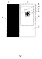
- a dark defect 8 is to be recognized, which is located on a light structured surface 2 , for example a wooden surface, which has a dark background 1 and with which it forms a typical edge 3 (FIG. 1).
- the surface brightness I surf from the test area 4 can be determined.
- the standard deviation ⁇ of the grayscale profile (FIG. 3), which runs along a search line 7 that extends across a typical edge 3, for example from the dark background area 1 to the light surface area 2 ( FIG. 1 ), can be used, for example, using the least squares method be determined.
- the histogram and the gray value profile have a Gaussian or a profile resulting from several Gaussian distributions. This means that these curves represent a normal Gaussian distribution and thus an exponential function and therefore have certain relationships between characteristic points.
- the brightness factor ⁇ 0 thus represents a minimal relationship between the brightness of the first possible edge position 3 and the background 1 :
- the standard deviation ⁇ of this profile can be determined as a Gaussian profile from the gray value profile (FIG. 3) with the aid of known conventional calculation methods, for example the least squares method.
- the gray value profile In order to be able to find the position of the edge 3 to be examined on the gray value profile, the gray value profile should be searched with a test track.
- this test section L 0 must not be less than the distance between the turning point ( I turn ) and the edge point (background brightness I bgrd ), which corresponds to the standard deviation ⁇ of the gray scale profile .
- the test section L 0 must not exceed twice the size of the standard deviation ⁇ . Otherwise the test section becomes larger than the entire transition region 10 between the background 1 and the surface 2 ( FIG. 3 ).
- the edge search can only be based on the edge-specific minimum brightness gradient ⁇ I 0 , without taking into account the edge-specific minimum brightness I 0 , which is an important condition for adaptive edge detection. Therefore: ⁇ ⁇ L 0 ⁇ 2 * ⁇ .
- the local minimum brightness I min does not yet correspond to the surface brightness ( I min ⁇ I surf ) but no longer corresponds to the background brightness ( I min > I bgrd ). It now points to a transition region 10 between the background 1 and the surface 2, in which an edge 3 can be located, and thus determines the minimum brightness I 0 .
- the condition (9) should only be met in the case of a real edge.
- the search for an edge may only be started if the local brightness gradient ⁇ I within the test section L 0 edge-specific minimum brightness gradient ⁇ I 0 reached.
- the first position corresponds to the end point of the test section L 0 when conditions (8) and (9) are simultaneously met for the first time within the test section L 0 .
- the second position corresponds to the starting point of the test section L 0 when conditions (8) and (9) are fulfilled for the last time within the test section L 0 .
- the threshold values I bot and I top can be defined for the detection of the starting point 9 of an error 8 (FIG. 1) .
- I bgrd ⁇ I surf * ⁇ 2 The surface brightness I surf differs sufficiently from the background brightness I bgrd to be able to reliably detect an edge 3 arising between the surface 2 and the background 1 .
- I ( x - 1) I surf * e - ( s 0 -1) 2 2 * ⁇ 2 ,
- the threshold values I bot and I top for the detection of the starting point 9 from an error 8 can be defined such that the brightness of the error to be searched for is taken into account as if it were the background brightness I bgrd for the error edge detection .
- I offered I surf * ((1- ⁇ 2 ) * ⁇ 0 + ⁇ 2 ).
- I offered I surf * ((1 - ⁇ 2 ) * e - s 0 2 2 * ⁇ 2 + ⁇ 2 );
- I Top I surf * ((1 - ⁇ 2 ) * e - ( s 0 -1) 2 2 * ⁇ 2 + ⁇ 2 ) if: s 0 ⁇ 2, otherwise:
- the minimum surface brightness I top should be determined in an error-specific manner.
- d 0 ⁇ * 2 * 1n I surf * (1 - ⁇ 2 ) I ( x ) - I surf * ⁇ 2 ; if applies: I ( x )> I surf * ⁇ 2 .
- the local threshold values I bot_loc and I top_loc can be calculated analogously to the corresponding threshold values I bot and I top , so that instead of the surface brightness I surf a local one Surface brightness I surf_loc can be used.
- the determination of the surface brightness I surf or the local surface brightness I surf_loc from the histogram of the test area 4 or the auxiliary area 6 can be carried out with the aid of a brightness separation value I sprt .
- I bgrd_ max I surf * ⁇ 0 ,
- I sprt I Max _Section * ⁇ 0 .
- the adaptive method described above thus explicitly recognizes an error that is present on a structured surface.
Landscapes
- Engineering & Computer Science (AREA)
- General Physics & Mathematics (AREA)
- Computer Vision & Pattern Recognition (AREA)
- Physics & Mathematics (AREA)
- Life Sciences & Earth Sciences (AREA)
- Theoretical Computer Science (AREA)
- Signal Processing (AREA)
- Health & Medical Sciences (AREA)
- Quality & Reliability (AREA)
- Chemical & Material Sciences (AREA)
- Analytical Chemistry (AREA)
- Biochemistry (AREA)
- General Health & Medical Sciences (AREA)
- Immunology (AREA)
- Pathology (AREA)
- Image Analysis (AREA)
- Investigating Materials By The Use Of Optical Means Adapted For Particular Applications (AREA)
Applications Claiming Priority (2)
| Application Number | Priority Date | Filing Date | Title |
|---|---|---|---|
| DE2003126035 DE10326035B4 (de) | 2003-06-10 | 2003-06-10 | Verfahren zur adaptiven Fehlererkennung auf einer strukturierten Oberfläche |
| DE10326035 | 2003-06-10 |
Publications (2)
| Publication Number | Publication Date |
|---|---|
| EP1491879A2 true EP1491879A2 (fr) | 2004-12-29 |
| EP1491879A3 EP1491879A3 (fr) | 2005-01-19 |
Family
ID=33394811
Family Applications (1)
| Application Number | Title | Priority Date | Filing Date |
|---|---|---|---|
| EP04013428A Withdrawn EP1491879A3 (fr) | 2003-06-10 | 2004-06-08 | Procédé de reconnaissance adaptive de défauts sur une surface structurée |
Country Status (2)
| Country | Link |
|---|---|
| EP (1) | EP1491879A3 (fr) |
| DE (1) | DE10326035B4 (fr) |
Cited By (18)
| Publication number | Priority date | Publication date | Assignee | Title |
|---|---|---|---|---|
| DE102006044307A1 (de) * | 2006-09-17 | 2008-09-25 | Massen Machine Vision Systems Gmbh | Multisensorielle Inspektion von Naturholz-Oberflächen |
| CN106651831A (zh) * | 2016-09-30 | 2017-05-10 | 广西师范大学 | 一种竹块缺陷检测方法和系统 |
| CN112304957A (zh) * | 2020-11-20 | 2021-02-02 | 天津朗硕机器人科技有限公司 | 一种基于机器视觉的外观缺陷智能检测方法及系统 |
| CN113732265A (zh) * | 2021-06-16 | 2021-12-03 | 浙江路飞镁业有限公司 | 一种高强度镁制轮毂生产工艺 |
| CN113934190A (zh) * | 2021-12-17 | 2022-01-14 | 武汉春田纸品包装有限公司 | 一种基于机器视觉的瓦楞纸板生产质量调控方法 |
| CN114419025A (zh) * | 2022-01-27 | 2022-04-29 | 江苏泰和木业有限公司 | 一种基于图像处理的纤维板质量评估方法 |
| CN114486903A (zh) * | 2021-12-06 | 2022-05-13 | 浙江大学台州研究院 | 一种灰度自适应的卷材检测系统及装置、算法 |
| CN114581362A (zh) * | 2021-07-22 | 2022-06-03 | 正泰集团研发中心(上海)有限公司 | 光伏组件缺陷检测方法、装置、电子设备和可读存储介质 |
| CN115239714A (zh) * | 2022-09-22 | 2022-10-25 | 山东汇智家具股份有限公司 | 一种用于地板生产的原木材料分级评价方法 |
| CN115272321A (zh) * | 2022-09-28 | 2022-11-01 | 山东军冠纺织有限公司 | 一种基于机器视觉的纺织品缺陷检测方法 |
| CN115797361A (zh) * | 2023-02-13 | 2023-03-14 | 山东淼泰建筑科技有限公司 | 一种铝模板表面缺陷检测方法 |
| CN116152133A (zh) * | 2023-04-20 | 2023-05-23 | 山东超越纺织有限公司 | 基于人工智能的混纺缺陷检测方法 |
| CN116758067A (zh) * | 2023-08-16 | 2023-09-15 | 梁山县成浩型钢有限公司 | 基于特征匹配的金属结构件检测方法 |
| CN116778520A (zh) * | 2023-08-11 | 2023-09-19 | 山东省大数据中心 | 一种海量证照数据质量检验方法 |
| CN117745724A (zh) * | 2024-02-20 | 2024-03-22 | 高唐县瑞景精密机械有限公司 | 基于视觉分析的石材打磨加工缺陷区域分割方法 |
| CN118505677A (zh) * | 2024-07-08 | 2024-08-16 | 北京中航天佑科技有限公司 | 一种交通轨道形变检测方法、系统、设备及程序产品 |
| CN120047439A (zh) * | 2025-04-23 | 2025-05-27 | 宏芯科技(泉州)有限公司 | 一种硅光芯片的检测系统 |
| CN120182247A (zh) * | 2025-05-14 | 2025-06-20 | 西安威尔精密技术有限公司 | 基于机器视觉的注塑件涂层质量检测方法及系统 |
Families Citing this family (20)
| Publication number | Priority date | Publication date | Assignee | Title |
|---|---|---|---|---|
| US8693731B2 (en) | 2012-01-17 | 2014-04-08 | Leap Motion, Inc. | Enhanced contrast for object detection and characterization by optical imaging |
| US12260023B2 (en) | 2012-01-17 | 2025-03-25 | Ultrahaptics IP Two Limited | Systems and methods for machine control |
| US9501152B2 (en) | 2013-01-15 | 2016-11-22 | Leap Motion, Inc. | Free-space user interface and control using virtual constructs |
| US11493998B2 (en) | 2012-01-17 | 2022-11-08 | Ultrahaptics IP Two Limited | Systems and methods for machine control |
| US10691219B2 (en) | 2012-01-17 | 2020-06-23 | Ultrahaptics IP Two Limited | Systems and methods for machine control |
| US9679215B2 (en) | 2012-01-17 | 2017-06-13 | Leap Motion, Inc. | Systems and methods for machine control |
| CN104145276B (zh) * | 2012-01-17 | 2017-05-03 | 厉动公司 | 用于通过光学成像进行的对象检测和表征的增强对比度 |
| US8638989B2 (en) | 2012-01-17 | 2014-01-28 | Leap Motion, Inc. | Systems and methods for capturing motion in three-dimensional space |
| US20150253428A1 (en) | 2013-03-15 | 2015-09-10 | Leap Motion, Inc. | Determining positional information for an object in space |
| US9070019B2 (en) | 2012-01-17 | 2015-06-30 | Leap Motion, Inc. | Systems and methods for capturing motion in three-dimensional space |
| US9459697B2 (en) | 2013-01-15 | 2016-10-04 | Leap Motion, Inc. | Dynamic, free-space user interactions for machine control |
| US9916009B2 (en) | 2013-04-26 | 2018-03-13 | Leap Motion, Inc. | Non-tactile interface systems and methods |
| US10846942B1 (en) | 2013-08-29 | 2020-11-24 | Ultrahaptics IP Two Limited | Predictive information for free space gesture control and communication |
| US9632572B2 (en) | 2013-10-03 | 2017-04-25 | Leap Motion, Inc. | Enhanced field of view to augment three-dimensional (3D) sensory space for free-space gesture interpretation |
| US9996638B1 (en) | 2013-10-31 | 2018-06-12 | Leap Motion, Inc. | Predictive information for free space gesture control and communication |
| US9679197B1 (en) | 2014-03-13 | 2017-06-13 | Leap Motion, Inc. | Biometric aware object detection and tracking |
| US9785247B1 (en) | 2014-05-14 | 2017-10-10 | Leap Motion, Inc. | Systems and methods of tracking moving hands and recognizing gestural interactions |
| US9741169B1 (en) | 2014-05-20 | 2017-08-22 | Leap Motion, Inc. | Wearable augmented reality devices with object detection and tracking |
| JP2016038889A (ja) | 2014-08-08 | 2016-03-22 | リープ モーション, インコーポレーテッドLeap Motion, Inc. | モーション感知を伴う拡張現実 |
| US10656720B1 (en) | 2015-01-16 | 2020-05-19 | Ultrahaptics IP Two Limited | Mode switching for integrated gestural interaction and multi-user collaboration in immersive virtual reality environments |
Family Cites Families (10)
| Publication number | Priority date | Publication date | Assignee | Title |
|---|---|---|---|---|
| US5774572A (en) * | 1984-12-20 | 1998-06-30 | Orbotech Ltd. | Automatic visual inspection system |
| KR940007346B1 (ko) * | 1991-03-28 | 1994-08-13 | 삼성전자 주식회사 | 화상 처리 시스템의 엣지 검출 장치 |
| DE4435796C1 (de) * | 1994-10-06 | 1995-12-07 | Siemens Ag | Verfahren zur automatischen Erkennung von Kanten und Durchmessern in Bildern |
| JP3264932B2 (ja) * | 1995-01-31 | 2002-03-11 | ユナイテッド パーセル サービス オブ アメリカ インコーポレイテッド | テキストを含む画像における背景から前景を分離する方法及び装置 |
| EP0742431B1 (fr) * | 1995-05-10 | 2000-03-15 | Mahlo GmbH & Co. KG | Procédé et dispositif de détection de défauts dans des bandes de tissu ou analogue |
| JPH096957A (ja) * | 1995-06-23 | 1997-01-10 | Toshiba Corp | 濃度画像の2値化方法および画像2値化装置 |
| DE19549216C2 (de) * | 1995-12-30 | 1999-09-09 | Fraunhofer Ges Forschung | Verfahren zur Bildauswertung |
| US5774177A (en) * | 1996-09-11 | 1998-06-30 | Milliken Research Corporation | Textile fabric inspection system |
| DE19902401C2 (de) * | 1999-01-22 | 2001-02-01 | Wohlenberg Schneidesysteme Gmb | Verfahren und Vorrichtung zur Bestimmung der Geometrie von blattförmigem Gut oder Stapeln davon |
| CN1184796C (zh) * | 2001-07-26 | 2005-01-12 | 佳能株式会社 | 图象处理方法和设备以及图象处理系统 |
-
2003
- 2003-06-10 DE DE2003126035 patent/DE10326035B4/de not_active Withdrawn - After Issue
-
2004
- 2004-06-08 EP EP04013428A patent/EP1491879A3/fr not_active Withdrawn
Cited By (27)
| Publication number | Priority date | Publication date | Assignee | Title |
|---|---|---|---|---|
| DE102006044307A1 (de) * | 2006-09-17 | 2008-09-25 | Massen Machine Vision Systems Gmbh | Multisensorielle Inspektion von Naturholz-Oberflächen |
| CN106651831A (zh) * | 2016-09-30 | 2017-05-10 | 广西师范大学 | 一种竹块缺陷检测方法和系统 |
| CN106651831B (zh) * | 2016-09-30 | 2020-02-11 | 广西师范大学 | 一种竹块缺陷检测方法和系统 |
| CN112304957A (zh) * | 2020-11-20 | 2021-02-02 | 天津朗硕机器人科技有限公司 | 一种基于机器视觉的外观缺陷智能检测方法及系统 |
| CN113732265A (zh) * | 2021-06-16 | 2021-12-03 | 浙江路飞镁业有限公司 | 一种高强度镁制轮毂生产工艺 |
| CN114581362B (zh) * | 2021-07-22 | 2023-11-07 | 正泰集团研发中心(上海)有限公司 | 光伏组件缺陷检测方法、装置、电子设备和可读存储介质 |
| CN114581362A (zh) * | 2021-07-22 | 2022-06-03 | 正泰集团研发中心(上海)有限公司 | 光伏组件缺陷检测方法、装置、电子设备和可读存储介质 |
| CN114486903A (zh) * | 2021-12-06 | 2022-05-13 | 浙江大学台州研究院 | 一种灰度自适应的卷材检测系统及装置、算法 |
| CN114486903B (zh) * | 2021-12-06 | 2024-05-14 | 浙江大学台州研究院 | 一种灰度自适应的卷材检测系统及装置、算法 |
| CN113934190A (zh) * | 2021-12-17 | 2022-01-14 | 武汉春田纸品包装有限公司 | 一种基于机器视觉的瓦楞纸板生产质量调控方法 |
| CN114419025A (zh) * | 2022-01-27 | 2022-04-29 | 江苏泰和木业有限公司 | 一种基于图像处理的纤维板质量评估方法 |
| CN114419025B (zh) * | 2022-01-27 | 2025-05-09 | 上海真真向上知识产权代理有限公司 | 一种基于图像处理的纤维板质量评估方法 |
| CN115239714B (zh) * | 2022-09-22 | 2022-12-06 | 山东汇智家具股份有限公司 | 一种用于地板生产的原木材料分级评价方法 |
| CN115239714A (zh) * | 2022-09-22 | 2022-10-25 | 山东汇智家具股份有限公司 | 一种用于地板生产的原木材料分级评价方法 |
| CN115272321B (zh) * | 2022-09-28 | 2023-01-10 | 山东军冠纺织有限公司 | 一种基于机器视觉的纺织品缺陷检测方法 |
| CN115272321A (zh) * | 2022-09-28 | 2022-11-01 | 山东军冠纺织有限公司 | 一种基于机器视觉的纺织品缺陷检测方法 |
| CN115797361A (zh) * | 2023-02-13 | 2023-03-14 | 山东淼泰建筑科技有限公司 | 一种铝模板表面缺陷检测方法 |
| CN116152133A (zh) * | 2023-04-20 | 2023-05-23 | 山东超越纺织有限公司 | 基于人工智能的混纺缺陷检测方法 |
| CN116778520A (zh) * | 2023-08-11 | 2023-09-19 | 山东省大数据中心 | 一种海量证照数据质量检验方法 |
| CN116778520B (zh) * | 2023-08-11 | 2023-11-10 | 山东省大数据中心 | 一种海量证照数据质量检验方法 |
| CN116758067A (zh) * | 2023-08-16 | 2023-09-15 | 梁山县成浩型钢有限公司 | 基于特征匹配的金属结构件检测方法 |
| CN116758067B (zh) * | 2023-08-16 | 2023-12-01 | 梁山县成浩型钢有限公司 | 基于特征匹配的金属结构件检测方法 |
| CN117745724A (zh) * | 2024-02-20 | 2024-03-22 | 高唐县瑞景精密机械有限公司 | 基于视觉分析的石材打磨加工缺陷区域分割方法 |
| CN117745724B (zh) * | 2024-02-20 | 2024-04-26 | 高唐县瑞景精密机械有限公司 | 基于视觉分析的石材打磨加工缺陷区域分割方法 |
| CN118505677A (zh) * | 2024-07-08 | 2024-08-16 | 北京中航天佑科技有限公司 | 一种交通轨道形变检测方法、系统、设备及程序产品 |
| CN120047439A (zh) * | 2025-04-23 | 2025-05-27 | 宏芯科技(泉州)有限公司 | 一种硅光芯片的检测系统 |
| CN120182247A (zh) * | 2025-05-14 | 2025-06-20 | 西安威尔精密技术有限公司 | 基于机器视觉的注塑件涂层质量检测方法及系统 |
Also Published As
| Publication number | Publication date |
|---|---|
| DE10326035B4 (de) | 2005-12-22 |
| EP1491879A3 (fr) | 2005-01-19 |
| DE10326035A1 (de) | 2005-01-13 |
Similar Documents
| Publication | Publication Date | Title |
|---|---|---|
| EP1491879A2 (fr) | Procédé de reconnaissance adaptive de défauts sur une surface structurée | |
| DE10326033B4 (de) | Verfahren zur adaptiven Fehlererkennung auf einer inhomogenen Oberfläche | |
| DE19521346C2 (de) | Bilduntersuchungs/-Erkennungsverfahren, darin verwendetes Verfahren zur Erzeugung von Referenzdaten und Vorrichtungen dafür | |
| DE69625891T2 (de) | Verfahren und Gerät zum Identifizieren von Fingerabdrücken | |
| DE102011081668B4 (de) | Vorrichtung und Verfahren zur Bestimmung der Form des Endes einer Schweißnaht | |
| DE69818438T2 (de) | Verfahren zur kontrolle der oberfläche einer laufenden materialbahn mit bildsegmentierung zur umgrenzung von defektbereichen | |
| DE69623564T2 (de) | Gerät zur Extraktion von Fingerabdruckmerkmalen | |
| EP3985558B1 (fr) | Procédé ainsi que dispositif de classification des données de capteur | |
| EP3009984A1 (fr) | Système de détection pour codes optiques | |
| DE69821225T2 (de) | Verfahren zur kontrolle der oberfläche einer laufenden materialbahn mit vorklassifikation von ermittelten unregelmässigkeiten | |
| DE69831032T2 (de) | Verfahren und Vorrichtung zur Zeichenerkennung | |
| DE10326031B4 (de) | Verfahren zur adaptiven Kantenerkennung | |
| EP4285319B1 (fr) | Generation de donnees d'entrainement pour scans bidimensionnels d'un systeme radar terrestre | |
| DE10326032B4 (de) | Verfahren zum Selbsttest eines Bildverarbeitungssystems | |
| EP3576013A1 (fr) | Évaluation d'un parcours d'une voie ferroviaire | |
| DE102005025220B4 (de) | Gerät, Verfahren und Programm zum Beseitigen von Poren | |
| EP3655920B1 (fr) | Procédé et dispositif pour l'évaluation de sections d'images pour un calcul de correspondance | |
| EP1525554A1 (fr) | Procede pour analyser les signaux d'un capteur d'images electronique lors de la reconnaissance de modeles de contenus d'images d'un echantillon | |
| EP3142068B1 (fr) | Procede de detection tridimensionnelle d'objets | |
| DE102022208384A1 (de) | Verfahren zum Ermitteln eines Qualitätszustands eines Prüfobjekts | |
| DE102018217310A1 (de) | Verfahren zum Auswerten von Zeitseriensignalen | |
| DE102021202878A1 (de) | Verfahren zur Reichweitenbestimmung für einen LiDAR-Sensor | |
| EP1139285B1 (fr) | Procédé et dispositif pour contrôle ou inspection d'objets | |
| AT511399B1 (de) | Verfahren zur automatisierten klassifikation von einschlüssen | |
| DE10066189B4 (de) | Verfahren zur Erkennung von Objekten |
Legal Events
| Date | Code | Title | Description |
|---|---|---|---|
| PUAI | Public reference made under article 153(3) epc to a published international application that has entered the european phase |
Free format text: ORIGINAL CODE: 0009012 |
|
| PUAL | Search report despatched |
Free format text: ORIGINAL CODE: 0009013 |
|
| 17P | Request for examination filed |
Effective date: 20040701 |
|
| AK | Designated contracting states |
Kind code of ref document: A2 Designated state(s): AT BE BG CH CY CZ DE DK EE ES FI FR GB GR HU IE IT LI LU MC NL PL PT RO SE SI SK TR |
|
| AX | Request for extension of the european patent |
Extension state: AL HR LT LV MK |
|
| AK | Designated contracting states |
Kind code of ref document: A3 Designated state(s): AT BE BG CH CY CZ DE DK EE ES FI FR GB GR HU IE IT LI LU MC NL PL PT RO SE SI SK TR |
|
| AX | Request for extension of the european patent |
Extension state: AL HR LT LV MK |
|
| 17Q | First examination report despatched |
Effective date: 20050413 |
|
| AKX | Designation fees paid |
Designated state(s): AT BE BG CH CY CZ DE DK EE ES FI FR GB GR HU IE IT LI LU MC NL PL PT RO SE SI SK TR |
|
| STAA | Information on the status of an ep patent application or granted ep patent |
Free format text: STATUS: THE APPLICATION IS DEEMED TO BE WITHDRAWN |
|
| 18D | Application deemed to be withdrawn |
Effective date: 20120110 |