EP1491987A2 - Kühlung eines Computerbauteils - Google Patents
Kühlung eines Computerbauteils Download PDFInfo
- Publication number
- EP1491987A2 EP1491987A2 EP04009744A EP04009744A EP1491987A2 EP 1491987 A2 EP1491987 A2 EP 1491987A2 EP 04009744 A EP04009744 A EP 04009744A EP 04009744 A EP04009744 A EP 04009744A EP 1491987 A2 EP1491987 A2 EP 1491987A2
- Authority
- EP
- European Patent Office
- Prior art keywords
- heat
- heat sink
- housing
- cooling
- air
- Prior art date
- Legal status (The legal status is an assumption and is not a legal conclusion. Google has not performed a legal analysis and makes no representation as to the accuracy of the status listed.)
- Granted
Links
Images


Classifications
-
- G—PHYSICS
- G06—COMPUTING OR CALCULATING; COUNTING
- G06F—ELECTRIC DIGITAL DATA PROCESSING
- G06F1/00—Details not covered by groups G06F3/00 - G06F13/00 and G06F21/00
- G06F1/16—Constructional details or arrangements
- G06F1/20—Cooling means
-
- G—PHYSICS
- G06—COMPUTING OR CALCULATING; COUNTING
- G06F—ELECTRIC DIGITAL DATA PROCESSING
- G06F2200/00—Indexing scheme relating to G06F1/04 - G06F1/32
- G06F2200/20—Indexing scheme relating to G06F1/20
- G06F2200/201—Cooling arrangements using cooling fluid
Definitions
- the invention relates to a device for cooling a heat-generating component in the housing of a computer, wherein a first heat sink is arranged in the vicinity of the heat-generating component.
- a device for cooling a heat-developing component in the housing of a computer wherein a first heat sink is disposed in the vicinity of the heat-generating component, and wherein a second heat sink is connected to the first heat sink via at least one heat pipe, and the second heat sink surrounded by outside air.
- the lower temperature of the outside air is used.
- the thermal energy of the heat-generating component is dissipated by this over the first heat sink and partially released to the internal air in the housing. It thereby increases the temperature in the housing. As the temperature in the housing increases, the amount of heat energy which can be dissipated decreases via the housing interior air.
- a heat pipe is connected to the first heat sink, which produces an energetic connection with a second heat sink.
- this heat pipe is a medium which evaporates at the junction with the first heat sink and condenses at the junction to the second heat sink.
- the medium absorbs heat
- the steam rises within the heat pipe to the second heat sink and there passes through a condensation process, the heat to this heat sink.
- This process takes place in predetermined temperature ranges on the two heat sinks and is silent and wear-free.
- the condensed medium flows within the heat pipe back to the point of contact with the first heat sink.
- the second heat sink is used for the energy output of waste heat energy to the outside air surrounding the housing.
- the flow of the housing inner air is excited by a first fan.
- the fan is mounted directly on the first heat sink or a fan is used in the power supply module to excite the flow of the housing inside air.
- the second heat sink is not arranged directly on the housing outer wall, but arranged in a housing-internal cooling air shaft, which is flowed through with outside air.
- This cooling air duct has no connection with the inner air of the housing which is heated by the heat-generating components, so that it is ensured that the second heat sink is flowed around only by the cooler outside air.
- a second fan can be installed in this cooling air shaft.
- this second fan in a further embodiment is adjustable so that its speed and the associated noise is controlled depending on the required cooling capacity.
- a further embodiment of the invention provides, the cooling air duct, in which the second heat sink is arranged to design so that it has an opening to the housing inner side and thus also for the removal of already heated inside air is used.
- This embodiment offers the possibility, in a modification of the above-mentioned embodiment, of optimally adjusting the operating point of the entire cooling system to the conditions prevailing at the place of use.
- Figure 1 illustrates a first heat sink 1 and a second heat sink 2, which are connected to a heat pipe 3 and arranged in a housing 7 of a computer.
- the heat pipe 3 is connected at its one end to the heat sink 1 and at its second end connected to the heat sink 2.
- the use of two heat pipes, as shown in Figure 1, does not represent a supply and return line, but two self-contained heat pipes that absorb heat energy at the location of the heat sink 1 by an evaporation process of the medium located within the heat pipes, the Medium in gaseous form to the heat sink 2 rises, condenses there and flows back as condensate to the heat sink 1. This cycle takes place within each of the two illustrated tubes.
- the use of two tubes is advantageous over the use of a tube, as a higher heat output can be dissipated in a uniform distribution.
- the heat sink 2 is due to the arrangement outside of the housing 7 flows around the air whose temperature is lower than the air inside the housing. 7
- FIG. 2 shows the use of the cooling device in a housing 7, wherein the heat sink 1 is mounted on a CPU and is additionally provided with a first fan 5.
- This fan 5 excites the flow of cooling air within the housing 7, in particular around the cooling fins of the first heat sink.
- the second heat sink 2 is spatially above the first heat sink, so that the function of the heat pipe 3 is given.
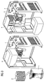
- FIG. 3 A further advantageous embodiment of the invention is shown in Figure 3, in which a cooling air duct 4 is disposed within the housing 7, while in turn the heat sink 2 is located.
- a cooling air duct 4 is disposed within the housing 7, while in turn the heat sink 2 is located.
- the cooling air duct ensures that the heat sink 2 is despite its location within the housing 7 flows around only cooler outside air.
- the first heat sink 1 is located on the CPU and the second heat sink 2 spatially above the first heat sink 1.
- a heat pipe 3 for transmitting the heat energy from the first heat sink 1 and second heat sink 2 is provided.
- a second fan 6 can be arranged in the cooling air duct for better cooling of the heat sink 2, so that the cooling capacity can be increased.
- FIG 4 illustrates an alternative embodiment of the variant shown in Figure 3.
- the cooling air duct in which the second heat sink 2 is arranged, provided with an opening in the direction of the housing interior, so that transported over this cooling air duct housing internal air to the outside and thus additionally Can absorb heat from the heat sink 2.
- the heat pipe which is often referred to as a heat pipe, is operated in an optimized operating point, or that the housing interior can be used for equipment internals.
Landscapes
- Engineering & Computer Science (AREA)
- Theoretical Computer Science (AREA)
- Human Computer Interaction (AREA)
- Physics & Mathematics (AREA)
- General Engineering & Computer Science (AREA)
- General Physics & Mathematics (AREA)
- Cooling Or The Like Of Electrical Apparatus (AREA)
Abstract
Description
- Die Erfindung betrifft eine Vorrichtung zur Kühlung eines hitzeentwickelnden Bauteils im Gehäuse eines Computers, wobei ein erster Kühlkörper in der Nähe des hitzeentwickelnden Bauteils angeordnet ist.
- Die durch den Betrieb von Computern, an Computerbauteilen entstehende Abwärmeleistung nimmt durch die gesteigerte Rechenleistung der Computerbauteile insbesondere der CPUs stark zu. Wird diese Abwärme nicht zuverlässig von dem hitzeentwickelnden Computerbauteil abgeführt, so droht eine thermische Überbelastung des Computerbauteils, deren Folge schließlich eine Zerstörung des Computerbauteils ist.
- Zur Erhaltung der Funktion und Betriebssicherheit des Computerbauteils ist deshalb die Ableitung der Abwärme von immenser Bedeutung. Es sind dazu verschiedene Systeme und Anordnungen bekannt, die allesamt zum allgemein bekannten Stand der Technik zählen. Dies sind in einer beispielhaften Aufzählung:
- 1. Große Kühlkörper in direkter Verbindung mit dem hitzeentwickelnden Bauteil, sowie Lüfter die eine Umströmung von Luft um das hitzeentwickelnde Bauteil und den damit verbundenen Kühlkörper bewirken.
- 2. Peltier-Kühlungen.
- 3. Kühlkreisläufe mit zum Beispiel Wasser als Medium.
- 4. Lüfterkaskaden, die für ausreichend kühle Frischluft im Gehäuse eines Computers sorgen.
- Um bei diesen Systemen der ständig steigenden Abwärme gerecht zu werden, müssen die Dimensionierungen dieser Systeme dem Abwärmebedarf angepaßt werden. Dies führt zu mehr Lüftern oder größeren Kühlkörpern. Die Folge ist eine höhere Geräuschentwicklung und/oder ein geringeres Platzangebot an verfügbaren Raum im Gehäuse eines Computers durch größer gewordene Kühlkörper.
- Es ist die Aufgabe der Erfindung, dem gestiegenen Bedarf an Kühlung gerecht zu werden, ohne dabei zusätzliche Geräuschentwicklung zu verursachen.
- Diese Aufgabe wird gelöst durch eine Vorrichtung zur Kühlung eines hitzeentwickelnden Bauteils im Gehäuse eines Computers, wobei ein erster Kühlkörper in der Nähe des hitzeentwickelnden Bauteils angeordnet ist, und wobei ein zweiter Kühlkörper mit dem ersten Kühlkörper über zumindest ein Wärmerohr verbunden ist, und der zweite Kühlkörper von Außenluft umgeben ist.
- Dabei wird vorteilhaft die geringere Temperatur der Außenluft genutzt. Die thermische Energie des hitzeentwickelnden Bauteils wird von diesem über den ersten Kühlkörper abgeführt und teilweise an die Innenluft im Gehäuse abgegeben. Es steigt dadurch die Temperatur im Gehäuse an. Mit steigender Temperatur im Gehäuse nimmt die Menge an abführbarer Wärmeenergie über die Gehäuse-Innenluft ab. Erfindungsgemäß ist mit dem ersten Kühlkörper ein Wärmerohr verbunden, das eine energetische Verbindung mit einem zweiten Kühlkörper herstellt. In diesem Wärmerohr befindet sich ein Medium, das an der Verbindungsstelle zum ersten Kühlkörper verdampft und an der Verbindungsstelle zum zweiten Kühlkörper kondensiert. Beim Verdampfungsprozess nimmt das Medium Wärme auf, der Dampf steigt innerhalb des Wärmerohres zum zweiten Kühlkörper und gibt dort durch einen Kondensationsprozeß die Wärme an diesen Kühlkörper ab. Dieser Prozeß findet in vorbestimmten Temperaturbereichen an den beiden Kühlkörpern statt und ist geräuschlos und verschleißfrei. Das kondensierte Medium fließt innerhalb des Wärmerohres zurück zur Kontaktstelle mit dem ersten Kühlkörper. Es wird somit der zweite Kühlkörper zur Energieabgabe von Abwärmeenergie an die das Gehäuse umgebende Außenluft genutzt.
- In einer vorteilhaften Ausführungsform ist die Strömung der Gehäuse-Innenluft durch einen ersten Ventilator angeregt. Der Ventilator ist hierzu unmittelbar auf den ersten Kühlkörper montiert oder es wird zur Anregung der Strömung der Gehäuse-Innenluft ein Ventilator im Stromversorgungsmodul verwendet.
- In einer weiteren vorteilhaften Ausführungsform ist der zweite Kühlkörper nicht unmittelbar an der Gehäuseaußenwand angeordnet, sondern in einem gehäuseinternen Kühlluftschacht angeordnet, der mit Außenluft durchströmt wird. Dieser Kühlluftschacht hat keine Verbindung mit der Innenluft des Gehäuses die durch die hitzeentwickelnden Bauteile erwärmt wird, so daß sichergestellt ist, daß der zweite Kühlkörper ausschließlich von der kühleren Außenluft umströmt wird. Vorteilhaft an dieser Ausführungsform ist, daß der zweite Kühlkörper ebenso wie alle anderen Komponenten des Computers durch das Gehäuse geschützt ist. Ebenso ist damit ein optimierter Arbeitspunkt für das Wärmerohr einstellbar.
- Um die Kühlleistung vorteilhaft zu verbessern, kann in diesem Kühlluftschacht ein zweiter Ventilator installiert werden. Dabei ist dieser zweite Ventilator in einer weiteren Ausführungsform so regelbar, daß seine Drehzahl und die damit einhergehende Geräuschentwicklung abhängig von der erforderlichen Kühlleistung gesteuert wird.
- Eine weitere Ausführungsform der Erfindung sieht vor, den Kühlluftschacht, in dem der zweite Kühlkörper angeordnet ist, so auszugestalten, daß er eine Öffnung zur Gehäuseinnenseite aufweist und damit auch zum Abtransport bereits erwärmter Innenluft verwendbar ist. Diese Ausführungsform bietet die Möglichkeit, in Abwandlung zu der oben genannten Ausführungsform den Arbeitspunkt des gesamten Kühlsystems auf die am Einsatzort vorherrschenden Bedingungen optimal abzustimmen.
- Im folgenden ist die Erfindung anhand einiger Ausführungsbeispiele und Figuren näher erläutert.
- Es zeigt:
- Figur 1 einen ersten Kühlkörper 1 und einen zweiten Kühlkörper 2, die verbunden sind mit einem Wärmerohr 3 und in einem Gehäuse 7 angeordnet sind, und
- Figur 2 die Anordnung aus Figur 1 mit einem Lüfter, und
- Figur 3 eine Ausführungsform der Erfindung, und
- Figur 4 eine weitere Ausführungsform der Erfindung.
- Figur 1 stellt einen ersten Kühlkörper 1 und einen zweiten Kühlkörper 2, die verbunden sind mit einem Wärmerohr 3 und in einem Gehäuse 7 eines Computers angeordnet sind, dar. Das Wärmerohr 3 ist an seinem einen Ende mit dem Kühlkörper 1 verbunden und an seinem zweiten Ende mit dem Kühlkörper 2 verbunden. Die Verwendung von zwei Wärmerohren, wie in der Figur 1 dargestellt, stellt keine Vor- und Rücklaufleitung dar, sondern zwei in sich geschlossene Wärmerohre, die durch einen Verdampfungsprozess des innerhalb der Wärmerohre befindlichen Mediums, Wärmeenergie an der Stelle des Kühlkörpers 1 aufnehmen, wobei das Medium in Gasform zum Kühlkörper 2 aufsteigt, dort kondensiert und als Kondensat zum Kühlkörper 1 zurückfließt. Dieser Kreislauf findet innerhalb eines jeden der beiden dargestellten Rohre statt. Die Verwendung von zwei Rohren ist vorteilhaft gegenüber der Verwendung von einem Rohr, da damit eine höhere Wärmeleistung in gleichmäßiger Verteilung abgeführt werden kann. Der Kühlkörper 2 wird, bedingt durch die Anordnung ausserhalb des Gehäuses 7 von Luft umströmt, deren Temperatur geringer ist, als die Luft innerhalb des Gehäuses 7.
- Figur 2 zeigt die Verwendung der Kühlvorrichtung in einem Gehäuse 7, wobei der Kühlkörper 1 auf eine CPU montiert ist und zusätzlich mit einem ersten Lüfter 5 versehen ist. Dieser Lüfter 5 regt die Strömung der Kühlluft innerhalb des Gehäuses 7 insbesondere um die Kühllamellen des ersten Kühlkörpers an. Der zweite Kühlkörper 2 befindet sich räumlich oberhalb des ersten Kühlkörpers, so daß die Funktion des Wärmerohres 3 gegeben ist.
- Eine weitere vorteilhafte Ausführungsform der Erfindung ist in Figur 3 dargestellt, in der ein Kühlluftschacht 4 innerhalb des Gehäuses 7 angeordnet ist, indessen wiederum sich der Kühlkörper 2 befindet. Durch den Kühlluftschacht ist gewährleistet, daß der Kühlkörper 2 trotz seiner Lage innerhalb des Gehäuses 7 ausschließlich von kühlerer Außenluft umströmt wird. Auch hier befindet sich der erste Kühlkörper 1 auf der CPU und der zweite Kühlkörper 2 räumlich überhalb des ersten Kühlkörpers 1. In diesem Ausführungsbeispiel ist ein Wärmerohr 3 zur Übertragung der Wärmeenergie von dem ersten Kühlkörper 1 und zweiten Kühlkörper 2 vorgesehen. Alternativ ist zur besseren Kühlung des Kühlkörpers 2 ein zweiter Ventilator 6 in den Kühlluftschacht anordenbar, so daß die Kühlleistung erhöhbar ist.
- Figur 4 stellt eine alternative Ausführungsform der in Figur 3 dargestellten Variante dar. So ist der Kühlluftschacht, in dem der zweite Kühlkörper 2 angeordnet ist, mit einer Öffnung in Richtung Gehäuseinneres versehen, so daß über diesen Kühlluftschacht Gehäuse-Innenluft nach außen abtransportiert und damit zusätzlich Wärme von dem Kühlkörper 2 aufnehmen kann. Diese beiden in Figur 3 und 4 dargestellten Ausführungsformen haben ihren Vorteil jeweils darin, daß damit das Kühlsystem im gesamten unterschiedlichen Ansprüchen und Standortbedingungen anpassbar ist. Damit kann auch erreicht werden, daß das Wärmerohr, das oft auch als Heat-Pipe bezeichnet wird, in einem optimierten Arbeitspunkt betrieben wird, oder daß der Gehäuseinnenraum für Geräteeinbauten genutzt werden kann.
Claims (8)
- Vorrichtung zur Kühlung eines hitzeentwickelnden Bauteils im Gehäuse (7) eines Computers, wobei ein erster Kühlkörper(1) in der Nähe des hitzeentwickelnden Bauteils angeordnet ist,dadurch gekennzeichnet, daß ein zweiter Kühlkörper (2) mit dem ersten Kühlkörper (1) über zumindest ein Wärmerohr (3) verbunden ist, und der zweite Kühlkörper (2) von Außenluft umgeben ist.
- Vorrichtung nach Patentanspruch 1,
dadurch gekennzeichnet, daß das Wärmerohr (3) mit einem Medium gefüllt ist, das am ersten Kühlkörper (1) verdampft und am zweiten Kühlkörper (2) kondensiert. - Vorrichtung nach Patentanspruch 1 - 2,
dadurch gekennzeichnet, daß die Strömung der Gehäuse-Innenluft durch einen ersten Ventilator (5) angeregt wird. - Vorrichtung nach einem der vorhergehenden Patentansprüche,
dadurch gekennzeichnet, daß das hitzeentwickelnde Computerbauteil eine CPU ist. - Vorrichtung nach einem der vorhergehenden Patentansprüche,
dadurch gekennzeichnet, daß der zweite Kühlkörper (2) in einem Kühlluftschacht (4) eingebettet ist, der innerhalb des Gehäuses (7) angeordnet ist und durch den Außenluft getrennt von der Innenluft strömt. - Vorrichtung nach Patentanspruch 4,
dadurch gekennzeichnet, daß der Kühlluftschacht eine Öffnung zur Gehäuseinnenseite hin aufweist, wobei Gehäuse-Innenluft durch den Kühlluftschacht nach außen und dabei um den zweiten Kühlkörper (2) strömt. - Vorrichtung nach Patentanspruch 4 bis 5,
dadurch gekennzeichnet, daß die Strömung im Kühlluftschacht (4) durch einen zweiten Ventilator (6) angeregt wird. - Vorrichtung nach Patentanspruch 6,
dadurch gekennzeichnet, daß der Ventilator (6) in Abhängigkeit der abzuführenden Wärmeenergie regelbar ist.
Applications Claiming Priority (2)
| Application Number | Priority Date | Filing Date | Title |
|---|---|---|---|
| DE20309965U DE20309965U1 (de) | 2003-06-27 | 2003-06-27 | Kühlung eines Computerbauteils |
| DE20309965U | 2003-06-27 |
Publications (3)
| Publication Number | Publication Date |
|---|---|
| EP1491987A2 true EP1491987A2 (de) | 2004-12-29 |
| EP1491987A3 EP1491987A3 (de) | 2006-06-21 |
| EP1491987B1 EP1491987B1 (de) | 2015-09-23 |
Family
ID=27816539
Family Applications (1)
| Application Number | Title | Priority Date | Filing Date |
|---|---|---|---|
| EP04009744.6A Expired - Lifetime EP1491987B1 (de) | 2003-06-27 | 2004-04-23 | Kühlung eines Computerbauteils |
Country Status (2)
| Country | Link |
|---|---|
| EP (1) | EP1491987B1 (de) |
| DE (1) | DE20309965U1 (de) |
Cited By (1)
| Publication number | Priority date | Publication date | Assignee | Title |
|---|---|---|---|---|
| RU2275764C1 (ru) * | 2005-08-08 | 2006-04-27 | Сергей Анатольевич Ермаков | Тепловая трубка с принудительной циркуляцией жидкости и тепловая трубка для охлаждения ноутбуков |
Families Citing this family (3)
| Publication number | Priority date | Publication date | Assignee | Title |
|---|---|---|---|---|
| US7359197B2 (en) | 2004-04-12 | 2008-04-15 | Nvidia Corporation | System for efficiently cooling a processor |
| DE102005019437A1 (de) * | 2005-01-25 | 2006-08-03 | Axel Benner | Computer |
| TWI361657B (en) * | 2007-12-17 | 2012-04-01 | Partner Tech Corp | Cooling module |
Citations (2)
| Publication number | Priority date | Publication date | Assignee | Title |
|---|---|---|---|---|
| US6333850B1 (en) | 1999-02-05 | 2001-12-25 | Foxconn Precision Components Co., Ltd. | Heat sink system |
| US6407916B1 (en) | 2000-06-12 | 2002-06-18 | Intel Corporation | Computer assembly for cooling high powered microprocessors |
Family Cites Families (5)
| Publication number | Priority date | Publication date | Assignee | Title |
|---|---|---|---|---|
| KR19980019402A (ko) * | 1998-03-16 | 1998-06-05 | 천기완 | 피.씨의 씨.피.유 냉각장치(cpu cooling device of pc) |
| DE29806082U1 (de) * | 1998-04-02 | 1998-06-18 | Ideal Electronics Inc., San Chung, Taipei | Kühleinrichtung für eine zentrale Recheneinheit |
| DE19944550A1 (de) * | 1999-09-17 | 2001-03-22 | In Blechverarbeitungszentrum S | Gehäuse mit elektrischen und/oder elektronischen Einheiten |
| JP2001159931A (ja) * | 1999-09-24 | 2001-06-12 | Cybernetics Technology Co Ltd | コンピュータ |
| US6445580B1 (en) * | 2000-06-09 | 2002-09-03 | International Business Machines Corporation | Adaptable heat dissipation device for a personal computer |
-
2003
- 2003-06-27 DE DE20309965U patent/DE20309965U1/de not_active Expired - Lifetime
-
2004
- 2004-04-23 EP EP04009744.6A patent/EP1491987B1/de not_active Expired - Lifetime
Patent Citations (2)
| Publication number | Priority date | Publication date | Assignee | Title |
|---|---|---|---|---|
| US6333850B1 (en) | 1999-02-05 | 2001-12-25 | Foxconn Precision Components Co., Ltd. | Heat sink system |
| US6407916B1 (en) | 2000-06-12 | 2002-06-18 | Intel Corporation | Computer assembly for cooling high powered microprocessors |
Cited By (1)
| Publication number | Priority date | Publication date | Assignee | Title |
|---|---|---|---|---|
| RU2275764C1 (ru) * | 2005-08-08 | 2006-04-27 | Сергей Анатольевич Ермаков | Тепловая трубка с принудительной циркуляцией жидкости и тепловая трубка для охлаждения ноутбуков |
Also Published As
| Publication number | Publication date |
|---|---|
| EP1491987A3 (de) | 2006-06-21 |
| DE20309965U1 (de) | 2003-09-04 |
| EP1491987B1 (de) | 2015-09-23 |
Similar Documents
| Publication | Publication Date | Title |
|---|---|---|
| DE69204018T2 (de) | Anordnung zur Kühlung von elektronischer Ausrüstung durch Strahlungstransfer. | |
| DE69603435T2 (de) | Verfahren zur Flüssigkeitskühlung eines Wechselrichters | |
| DE60315095T2 (de) | Thermosiphon für elektronische Geräte zum Kühlen mit einem ungleichmässigen Luftstrom | |
| EP1859336A2 (de) | Kühlsystem für elektronische geräte, insbesondere computer | |
| EP3105650B1 (de) | Kühlanordnung für ein computersystem | |
| DE102020112925A1 (de) | Entfeuchter-Einrichtung und eine diese aufweisende Ladestation | |
| EP1491987B1 (de) | Kühlung eines Computerbauteils | |
| DE102010054281B4 (de) | Elektronisches Gerät mit einem Gehäuse, in dem Wärme erzeugende Komponenten angeordnet sind | |
| DE19802008A1 (de) | Gefrier- und Kühlsystem und Wärmetauschervorrichtung zur Kondensation | |
| DE2732879A1 (de) | Waermetauscher | |
| EP0007396B1 (de) | Kühleinrichtung für in geschlossenen Gehäusen angeordnete elektrische Baueinheiten | |
| DE202004003644U1 (de) | Kühlsystem für ein elektronisches Gerät, insbesondere Computer | |
| DE102017127627B3 (de) | Kühlanordnung für einen elektrischen Antrieb | |
| EP3519914A1 (de) | Lichtstellpult mit kühleinrichtung | |
| EP2795127B1 (de) | Gerätegehäuse mit kühlvorrichtung für einströmende luft | |
| DE202017002476U1 (de) | Flüssigkeitsgekühlte Wärmesenke | |
| DE10350358B4 (de) | Verfahren und Vorrichtung zur Nutzbarmachung der Abwärme einer Anordnung mit einem oder mehreren Computern | |
| DE29821758U1 (de) | Kühlvorrichtung für Computerfunktionseinheiten | |
| EP1085795A2 (de) | Gehäuse mit elektrischen und/oder elektronischen Einheiten | |
| EP2375210A1 (de) | Thermosiphonanlage eines mindestens zwei Wärmequelle aufweisenden wärmeerzeugenden Systems | |
| DE29620019U1 (de) | Wärmeableitungsvorrichtung für Halbleiter-Bausteine | |
| EP3629688A1 (de) | Stromrichter mit einem separaten innenraum | |
| DE102004051393A1 (de) | Lufthutzenkühler | |
| DE202022100705U1 (de) | Pumpenloser Flüssigkeitskühler | |
| EP4071800A1 (de) | Halbleiterchipanordnung mit kühlung |
Legal Events
| Date | Code | Title | Description |
|---|---|---|---|
| PUAI | Public reference made under article 153(3) epc to a published international application that has entered the european phase |
Free format text: ORIGINAL CODE: 0009012 |
|
| AK | Designated contracting states |
Kind code of ref document: A2 Designated state(s): AT BE BG CH CY CZ DE DK EE ES FI FR GB GR HU IE IT LI LU MC NL PL PT RO SE SI SK TR |
|
| AX | Request for extension of the european patent |
Extension state: AL HR LT LV MK |
|
| PUAL | Search report despatched |
Free format text: ORIGINAL CODE: 0009013 |
|
| AK | Designated contracting states |
Kind code of ref document: A3 Designated state(s): AT BE BG CH CY CZ DE DK EE ES FI FR GB GR HU IE IT LI LU MC NL PL PT RO SE SI SK TR |
|
| AX | Request for extension of the european patent |
Extension state: AL HR LT LV MK |
|
| 17P | Request for examination filed |
Effective date: 20060726 |
|
| 17Q | First examination report despatched |
Effective date: 20060828 |
|
| AKX | Designation fees paid |
Designated state(s): DE FR GB NL |
|
| 17Q | First examination report despatched |
Effective date: 20060828 |
|
| APBK | Appeal reference recorded |
Free format text: ORIGINAL CODE: EPIDOSNREFNE |
|
| APBN | Date of receipt of notice of appeal recorded |
Free format text: ORIGINAL CODE: EPIDOSNNOA2E |
|
| RAP1 | Party data changed (applicant data changed or rights of an application transferred) |
Owner name: FUJITSU TECHNOLOGY SOLUTIONS GMBH |
|
| APBR | Date of receipt of statement of grounds of appeal recorded |
Free format text: ORIGINAL CODE: EPIDOSNNOA3E |
|
| RAP1 | Party data changed (applicant data changed or rights of an application transferred) |
Owner name: FUJITSU TECHNOLOGY SOLUTIONS INTELLECTUAL PROPERTY |
|
| APAF | Appeal reference modified |
Free format text: ORIGINAL CODE: EPIDOSCREFNE |
|
| APBT | Appeal procedure closed |
Free format text: ORIGINAL CODE: EPIDOSNNOA9E |
|
| GRAP | Despatch of communication of intention to grant a patent |
Free format text: ORIGINAL CODE: EPIDOSNIGR1 |
|
| INTG | Intention to grant announced |
Effective date: 20150609 |
|
| GRAS | Grant fee paid |
Free format text: ORIGINAL CODE: EPIDOSNIGR3 |
|
| GRAA | (expected) grant |
Free format text: ORIGINAL CODE: 0009210 |
|
| AK | Designated contracting states |
Kind code of ref document: B1 Designated state(s): DE FR GB NL |
|
| REG | Reference to a national code |
Ref country code: GB Ref legal event code: FG4D Free format text: NOT ENGLISH |
|
| REG | Reference to a national code |
Ref country code: DE Ref legal event code: R096 Ref document number: 502004015029 Country of ref document: DE |
|
| REG | Reference to a national code |
Ref country code: NL Ref legal event code: MP Effective date: 20150923 |
|
| PG25 | Lapsed in a contracting state [announced via postgrant information from national office to epo] |
Ref country code: NL Free format text: LAPSE BECAUSE OF FAILURE TO SUBMIT A TRANSLATION OF THE DESCRIPTION OR TO PAY THE FEE WITHIN THE PRESCRIBED TIME-LIMIT Effective date: 20150923 |
|
| REG | Reference to a national code |
Ref country code: FR Ref legal event code: PLFP Year of fee payment: 13 |
|
| REG | Reference to a national code |
Ref country code: DE Ref legal event code: R097 Ref document number: 502004015029 Country of ref document: DE |
|
| PLBE | No opposition filed within time limit |
Free format text: ORIGINAL CODE: 0009261 |
|
| STAA | Information on the status of an ep patent application or granted ep patent |
Free format text: STATUS: NO OPPOSITION FILED WITHIN TIME LIMIT |
|
| 26N | No opposition filed |
Effective date: 20160624 |
|
| REG | Reference to a national code |
Ref country code: FR Ref legal event code: PLFP Year of fee payment: 14 |
|
| REG | Reference to a national code |
Ref country code: FR Ref legal event code: PLFP Year of fee payment: 15 |
|
| REG | Reference to a national code |
Ref country code: DE Ref legal event code: R082 Ref document number: 502004015029 Country of ref document: DE Representative=s name: EPPING HERMANN FISCHER PATENTANWALTSGESELLSCHA, DE Ref country code: DE Ref legal event code: R081 Ref document number: 502004015029 Country of ref document: DE Owner name: FUJITSU CLIENT COMPUTING LIMITED, KAWASAKI-SHI, JP Free format text: FORMER OWNER: FUJITSU TECHNOLOGY SOLUTIONS INTELLECTUAL PROPERTY GMBH, 80807 MUENCHEN, DE |
|
| REG | Reference to a national code |
Ref country code: GB Ref legal event code: 732E Free format text: REGISTERED BETWEEN 20190725 AND 20190731 |
|
| PGFP | Annual fee paid to national office [announced via postgrant information from national office to epo] |
Ref country code: FR Payment date: 20230417 Year of fee payment: 20 |
|
| PGFP | Annual fee paid to national office [announced via postgrant information from national office to epo] |
Ref country code: GB Payment date: 20230413 Year of fee payment: 20 |
|
| REG | Reference to a national code |
Ref country code: DE Ref legal event code: R409 Ref document number: 502004015029 Country of ref document: DE Ref country code: DE Ref legal event code: R119 Ref document number: 502004015029 Country of ref document: DE |
|
| PG25 | Lapsed in a contracting state [announced via postgrant information from national office to epo] |
Ref country code: DE Free format text: LAPSE BECAUSE OF NON-PAYMENT OF DUE FEES Effective date: 20231103 |
|
| PGFP | Annual fee paid to national office [announced via postgrant information from national office to epo] |
Ref country code: DE Payment date: 20230424 Year of fee payment: 20 |
|
| REG | Reference to a national code |
Ref country code: DE Ref legal event code: R071 Ref document number: 502004015029 Country of ref document: DE |
|
| REG | Reference to a national code |
Ref country code: GB Ref legal event code: PE20 Expiry date: 20240422 |
|
| PG25 | Lapsed in a contracting state [announced via postgrant information from national office to epo] |
Ref country code: GB Free format text: LAPSE BECAUSE OF EXPIRATION OF PROTECTION Effective date: 20240422 |
|
| PG25 | Lapsed in a contracting state [announced via postgrant information from national office to epo] |
Ref country code: GB Free format text: LAPSE BECAUSE OF EXPIRATION OF PROTECTION Effective date: 20240422 |