EP1491987A2 - Refroidissement d'un composant d'ordinateur - Google Patents
Refroidissement d'un composant d'ordinateur Download PDFInfo
- Publication number
- EP1491987A2 EP1491987A2 EP04009744A EP04009744A EP1491987A2 EP 1491987 A2 EP1491987 A2 EP 1491987A2 EP 04009744 A EP04009744 A EP 04009744A EP 04009744 A EP04009744 A EP 04009744A EP 1491987 A2 EP1491987 A2 EP 1491987A2
- Authority
- EP
- European Patent Office
- Prior art keywords
- heat
- heat sink
- housing
- cooling
- air
- Prior art date
- Legal status (The legal status is an assumption and is not a legal conclusion. Google has not performed a legal analysis and makes no representation as to the accuracy of the status listed.)
- Granted
Links
Images


Classifications
-
- G—PHYSICS
- G06—COMPUTING OR CALCULATING; COUNTING
- G06F—ELECTRIC DIGITAL DATA PROCESSING
- G06F1/00—Details not covered by groups G06F3/00 - G06F13/00 and G06F21/00
- G06F1/16—Constructional details or arrangements
- G06F1/20—Cooling means
-
- G—PHYSICS
- G06—COMPUTING OR CALCULATING; COUNTING
- G06F—ELECTRIC DIGITAL DATA PROCESSING
- G06F2200/00—Indexing scheme relating to G06F1/04 - G06F1/32
- G06F2200/20—Indexing scheme relating to G06F1/20
- G06F2200/201—Cooling arrangements using cooling fluid
Definitions
- the invention relates to a device for cooling a heat-generating component in the housing of a computer, wherein a first heat sink is arranged in the vicinity of the heat-generating component.
- a device for cooling a heat-developing component in the housing of a computer wherein a first heat sink is disposed in the vicinity of the heat-generating component, and wherein a second heat sink is connected to the first heat sink via at least one heat pipe, and the second heat sink surrounded by outside air.
- the lower temperature of the outside air is used.
- the thermal energy of the heat-generating component is dissipated by this over the first heat sink and partially released to the internal air in the housing. It thereby increases the temperature in the housing. As the temperature in the housing increases, the amount of heat energy which can be dissipated decreases via the housing interior air.
- a heat pipe is connected to the first heat sink, which produces an energetic connection with a second heat sink.
- this heat pipe is a medium which evaporates at the junction with the first heat sink and condenses at the junction to the second heat sink.
- the medium absorbs heat
- the steam rises within the heat pipe to the second heat sink and there passes through a condensation process, the heat to this heat sink.
- This process takes place in predetermined temperature ranges on the two heat sinks and is silent and wear-free.
- the condensed medium flows within the heat pipe back to the point of contact with the first heat sink.
- the second heat sink is used for the energy output of waste heat energy to the outside air surrounding the housing.
- the flow of the housing inner air is excited by a first fan.
- the fan is mounted directly on the first heat sink or a fan is used in the power supply module to excite the flow of the housing inside air.
- the second heat sink is not arranged directly on the housing outer wall, but arranged in a housing-internal cooling air shaft, which is flowed through with outside air.
- This cooling air duct has no connection with the inner air of the housing which is heated by the heat-generating components, so that it is ensured that the second heat sink is flowed around only by the cooler outside air.
- a second fan can be installed in this cooling air shaft.
- this second fan in a further embodiment is adjustable so that its speed and the associated noise is controlled depending on the required cooling capacity.
- a further embodiment of the invention provides, the cooling air duct, in which the second heat sink is arranged to design so that it has an opening to the housing inner side and thus also for the removal of already heated inside air is used.
- This embodiment offers the possibility, in a modification of the above-mentioned embodiment, of optimally adjusting the operating point of the entire cooling system to the conditions prevailing at the place of use.
- Figure 1 illustrates a first heat sink 1 and a second heat sink 2, which are connected to a heat pipe 3 and arranged in a housing 7 of a computer.
- the heat pipe 3 is connected at its one end to the heat sink 1 and at its second end connected to the heat sink 2.
- the use of two heat pipes, as shown in Figure 1, does not represent a supply and return line, but two self-contained heat pipes that absorb heat energy at the location of the heat sink 1 by an evaporation process of the medium located within the heat pipes, the Medium in gaseous form to the heat sink 2 rises, condenses there and flows back as condensate to the heat sink 1. This cycle takes place within each of the two illustrated tubes.
- the use of two tubes is advantageous over the use of a tube, as a higher heat output can be dissipated in a uniform distribution.
- the heat sink 2 is due to the arrangement outside of the housing 7 flows around the air whose temperature is lower than the air inside the housing. 7
- FIG. 2 shows the use of the cooling device in a housing 7, wherein the heat sink 1 is mounted on a CPU and is additionally provided with a first fan 5.
- This fan 5 excites the flow of cooling air within the housing 7, in particular around the cooling fins of the first heat sink.
- the second heat sink 2 is spatially above the first heat sink, so that the function of the heat pipe 3 is given.
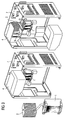
- FIG. 3 A further advantageous embodiment of the invention is shown in Figure 3, in which a cooling air duct 4 is disposed within the housing 7, while in turn the heat sink 2 is located.
- a cooling air duct 4 is disposed within the housing 7, while in turn the heat sink 2 is located.
- the cooling air duct ensures that the heat sink 2 is despite its location within the housing 7 flows around only cooler outside air.
- the first heat sink 1 is located on the CPU and the second heat sink 2 spatially above the first heat sink 1.
- a heat pipe 3 for transmitting the heat energy from the first heat sink 1 and second heat sink 2 is provided.
- a second fan 6 can be arranged in the cooling air duct for better cooling of the heat sink 2, so that the cooling capacity can be increased.
- FIG 4 illustrates an alternative embodiment of the variant shown in Figure 3.
- the cooling air duct in which the second heat sink 2 is arranged, provided with an opening in the direction of the housing interior, so that transported over this cooling air duct housing internal air to the outside and thus additionally Can absorb heat from the heat sink 2.
- the heat pipe which is often referred to as a heat pipe, is operated in an optimized operating point, or that the housing interior can be used for equipment internals.
Landscapes
- Engineering & Computer Science (AREA)
- Theoretical Computer Science (AREA)
- Human Computer Interaction (AREA)
- Physics & Mathematics (AREA)
- General Engineering & Computer Science (AREA)
- General Physics & Mathematics (AREA)
- Cooling Or The Like Of Electrical Apparatus (AREA)
Applications Claiming Priority (2)
| Application Number | Priority Date | Filing Date | Title |
|---|---|---|---|
| DE20309965U DE20309965U1 (de) | 2003-06-27 | 2003-06-27 | Kühlung eines Computerbauteils |
| DE20309965U | 2003-06-27 |
Publications (3)
| Publication Number | Publication Date |
|---|---|
| EP1491987A2 true EP1491987A2 (fr) | 2004-12-29 |
| EP1491987A3 EP1491987A3 (fr) | 2006-06-21 |
| EP1491987B1 EP1491987B1 (fr) | 2015-09-23 |
Family
ID=27816539
Family Applications (1)
| Application Number | Title | Priority Date | Filing Date |
|---|---|---|---|
| EP04009744.6A Expired - Lifetime EP1491987B1 (fr) | 2003-06-27 | 2004-04-23 | Refroidissement d'un composant d'ordinateur |
Country Status (2)
| Country | Link |
|---|---|
| EP (1) | EP1491987B1 (fr) |
| DE (1) | DE20309965U1 (fr) |
Cited By (1)
| Publication number | Priority date | Publication date | Assignee | Title |
|---|---|---|---|---|
| RU2275764C1 (ru) * | 2005-08-08 | 2006-04-27 | Сергей Анатольевич Ермаков | Тепловая трубка с принудительной циркуляцией жидкости и тепловая трубка для охлаждения ноутбуков |
Families Citing this family (3)
| Publication number | Priority date | Publication date | Assignee | Title |
|---|---|---|---|---|
| US7359197B2 (en) | 2004-04-12 | 2008-04-15 | Nvidia Corporation | System for efficiently cooling a processor |
| DE102005019437A1 (de) * | 2005-01-25 | 2006-08-03 | Axel Benner | Computer |
| TWI361657B (en) * | 2007-12-17 | 2012-04-01 | Partner Tech Corp | Cooling module |
Citations (2)
| Publication number | Priority date | Publication date | Assignee | Title |
|---|---|---|---|---|
| US6333850B1 (en) | 1999-02-05 | 2001-12-25 | Foxconn Precision Components Co., Ltd. | Heat sink system |
| US6407916B1 (en) | 2000-06-12 | 2002-06-18 | Intel Corporation | Computer assembly for cooling high powered microprocessors |
Family Cites Families (5)
| Publication number | Priority date | Publication date | Assignee | Title |
|---|---|---|---|---|
| KR19980019402A (ko) * | 1998-03-16 | 1998-06-05 | 천기완 | 피.씨의 씨.피.유 냉각장치(cpu cooling device of pc) |
| DE29806082U1 (de) * | 1998-04-02 | 1998-06-18 | Ideal Electronics Inc., San Chung, Taipei | Kühleinrichtung für eine zentrale Recheneinheit |
| DE19944550A1 (de) * | 1999-09-17 | 2001-03-22 | In Blechverarbeitungszentrum S | Gehäuse mit elektrischen und/oder elektronischen Einheiten |
| JP2001159931A (ja) * | 1999-09-24 | 2001-06-12 | Cybernetics Technology Co Ltd | コンピュータ |
| US6445580B1 (en) * | 2000-06-09 | 2002-09-03 | International Business Machines Corporation | Adaptable heat dissipation device for a personal computer |
-
2003
- 2003-06-27 DE DE20309965U patent/DE20309965U1/de not_active Expired - Lifetime
-
2004
- 2004-04-23 EP EP04009744.6A patent/EP1491987B1/fr not_active Expired - Lifetime
Patent Citations (2)
| Publication number | Priority date | Publication date | Assignee | Title |
|---|---|---|---|---|
| US6333850B1 (en) | 1999-02-05 | 2001-12-25 | Foxconn Precision Components Co., Ltd. | Heat sink system |
| US6407916B1 (en) | 2000-06-12 | 2002-06-18 | Intel Corporation | Computer assembly for cooling high powered microprocessors |
Cited By (1)
| Publication number | Priority date | Publication date | Assignee | Title |
|---|---|---|---|---|
| RU2275764C1 (ru) * | 2005-08-08 | 2006-04-27 | Сергей Анатольевич Ермаков | Тепловая трубка с принудительной циркуляцией жидкости и тепловая трубка для охлаждения ноутбуков |
Also Published As
| Publication number | Publication date |
|---|---|
| EP1491987A3 (fr) | 2006-06-21 |
| DE20309965U1 (de) | 2003-09-04 |
| EP1491987B1 (fr) | 2015-09-23 |
Similar Documents
| Publication | Publication Date | Title |
|---|---|---|
| DE69204018T2 (de) | Anordnung zur Kühlung von elektronischer Ausrüstung durch Strahlungstransfer. | |
| DE69603435T2 (de) | Verfahren zur Flüssigkeitskühlung eines Wechselrichters | |
| DE60315095T2 (de) | Thermosiphon für elektronische Geräte zum Kühlen mit einem ungleichmässigen Luftstrom | |
| EP1859336A2 (fr) | Systeme de refroidissement pour des appareils electroniques, en particulier des ordinateurs | |
| EP3105650B1 (fr) | Circuit de refroidissement pour un système d'ordinateur | |
| DE102020112925A1 (de) | Entfeuchter-Einrichtung und eine diese aufweisende Ladestation | |
| EP1491987B1 (fr) | Refroidissement d'un composant d'ordinateur | |
| DE102010054281B4 (de) | Elektronisches Gerät mit einem Gehäuse, in dem Wärme erzeugende Komponenten angeordnet sind | |
| DE19802008A1 (de) | Gefrier- und Kühlsystem und Wärmetauschervorrichtung zur Kondensation | |
| DE2732879A1 (de) | Waermetauscher | |
| EP0007396B1 (fr) | Dispositif de refroidissement pour unités de montage électriques disposées dans une boîte close | |
| DE202004003644U1 (de) | Kühlsystem für ein elektronisches Gerät, insbesondere Computer | |
| DE102017127627B3 (de) | Kühlanordnung für einen elektrischen Antrieb | |
| EP3519914A1 (fr) | Pupitre d'éclairage pourvu d'un dispositif de refroidissement | |
| EP2795127B1 (fr) | Boîtier d'un appareil avec des moyens pour refroidir de l'air entrant ledit boîtier | |
| DE202017002476U1 (de) | Flüssigkeitsgekühlte Wärmesenke | |
| DE10350358B4 (de) | Verfahren und Vorrichtung zur Nutzbarmachung der Abwärme einer Anordnung mit einem oder mehreren Computern | |
| DE29821758U1 (de) | Kühlvorrichtung für Computerfunktionseinheiten | |
| EP1085795A2 (fr) | Receptacle aver des unités électriques et/ou électroniques | |
| EP2375210A1 (fr) | Installation de thermosiphon d'un système produisant de la chaleur et comprenant au moins deux sources de chaleur | |
| DE29620019U1 (de) | Wärmeableitungsvorrichtung für Halbleiter-Bausteine | |
| EP3629688A1 (fr) | Convertisseur de courant doté d'un espace intérieur séparé | |
| DE102004051393A1 (de) | Lufthutzenkühler | |
| DE202022100705U1 (de) | Pumpenloser Flüssigkeitskühler | |
| EP4071800A1 (fr) | Agencement de puces à semi-conducteur à refroidissement |
Legal Events
| Date | Code | Title | Description |
|---|---|---|---|
| PUAI | Public reference made under article 153(3) epc to a published international application that has entered the european phase |
Free format text: ORIGINAL CODE: 0009012 |
|
| AK | Designated contracting states |
Kind code of ref document: A2 Designated state(s): AT BE BG CH CY CZ DE DK EE ES FI FR GB GR HU IE IT LI LU MC NL PL PT RO SE SI SK TR |
|
| AX | Request for extension of the european patent |
Extension state: AL HR LT LV MK |
|
| PUAL | Search report despatched |
Free format text: ORIGINAL CODE: 0009013 |
|
| AK | Designated contracting states |
Kind code of ref document: A3 Designated state(s): AT BE BG CH CY CZ DE DK EE ES FI FR GB GR HU IE IT LI LU MC NL PL PT RO SE SI SK TR |
|
| AX | Request for extension of the european patent |
Extension state: AL HR LT LV MK |
|
| 17P | Request for examination filed |
Effective date: 20060726 |
|
| 17Q | First examination report despatched |
Effective date: 20060828 |
|
| AKX | Designation fees paid |
Designated state(s): DE FR GB NL |
|
| 17Q | First examination report despatched |
Effective date: 20060828 |
|
| APBK | Appeal reference recorded |
Free format text: ORIGINAL CODE: EPIDOSNREFNE |
|
| APBN | Date of receipt of notice of appeal recorded |
Free format text: ORIGINAL CODE: EPIDOSNNOA2E |
|
| RAP1 | Party data changed (applicant data changed or rights of an application transferred) |
Owner name: FUJITSU TECHNOLOGY SOLUTIONS GMBH |
|
| APBR | Date of receipt of statement of grounds of appeal recorded |
Free format text: ORIGINAL CODE: EPIDOSNNOA3E |
|
| RAP1 | Party data changed (applicant data changed or rights of an application transferred) |
Owner name: FUJITSU TECHNOLOGY SOLUTIONS INTELLECTUAL PROPERTY |
|
| APAF | Appeal reference modified |
Free format text: ORIGINAL CODE: EPIDOSCREFNE |
|
| APBT | Appeal procedure closed |
Free format text: ORIGINAL CODE: EPIDOSNNOA9E |
|
| GRAP | Despatch of communication of intention to grant a patent |
Free format text: ORIGINAL CODE: EPIDOSNIGR1 |
|
| INTG | Intention to grant announced |
Effective date: 20150609 |
|
| GRAS | Grant fee paid |
Free format text: ORIGINAL CODE: EPIDOSNIGR3 |
|
| GRAA | (expected) grant |
Free format text: ORIGINAL CODE: 0009210 |
|
| AK | Designated contracting states |
Kind code of ref document: B1 Designated state(s): DE FR GB NL |
|
| REG | Reference to a national code |
Ref country code: GB Ref legal event code: FG4D Free format text: NOT ENGLISH |
|
| REG | Reference to a national code |
Ref country code: DE Ref legal event code: R096 Ref document number: 502004015029 Country of ref document: DE |
|
| REG | Reference to a national code |
Ref country code: NL Ref legal event code: MP Effective date: 20150923 |
|
| PG25 | Lapsed in a contracting state [announced via postgrant information from national office to epo] |
Ref country code: NL Free format text: LAPSE BECAUSE OF FAILURE TO SUBMIT A TRANSLATION OF THE DESCRIPTION OR TO PAY THE FEE WITHIN THE PRESCRIBED TIME-LIMIT Effective date: 20150923 |
|
| REG | Reference to a national code |
Ref country code: FR Ref legal event code: PLFP Year of fee payment: 13 |
|
| REG | Reference to a national code |
Ref country code: DE Ref legal event code: R097 Ref document number: 502004015029 Country of ref document: DE |
|
| PLBE | No opposition filed within time limit |
Free format text: ORIGINAL CODE: 0009261 |
|
| STAA | Information on the status of an ep patent application or granted ep patent |
Free format text: STATUS: NO OPPOSITION FILED WITHIN TIME LIMIT |
|
| 26N | No opposition filed |
Effective date: 20160624 |
|
| REG | Reference to a national code |
Ref country code: FR Ref legal event code: PLFP Year of fee payment: 14 |
|
| REG | Reference to a national code |
Ref country code: FR Ref legal event code: PLFP Year of fee payment: 15 |
|
| REG | Reference to a national code |
Ref country code: DE Ref legal event code: R082 Ref document number: 502004015029 Country of ref document: DE Representative=s name: EPPING HERMANN FISCHER PATENTANWALTSGESELLSCHA, DE Ref country code: DE Ref legal event code: R081 Ref document number: 502004015029 Country of ref document: DE Owner name: FUJITSU CLIENT COMPUTING LIMITED, KAWASAKI-SHI, JP Free format text: FORMER OWNER: FUJITSU TECHNOLOGY SOLUTIONS INTELLECTUAL PROPERTY GMBH, 80807 MUENCHEN, DE |
|
| REG | Reference to a national code |
Ref country code: GB Ref legal event code: 732E Free format text: REGISTERED BETWEEN 20190725 AND 20190731 |
|
| PGFP | Annual fee paid to national office [announced via postgrant information from national office to epo] |
Ref country code: FR Payment date: 20230417 Year of fee payment: 20 |
|
| PGFP | Annual fee paid to national office [announced via postgrant information from national office to epo] |
Ref country code: GB Payment date: 20230413 Year of fee payment: 20 |
|
| REG | Reference to a national code |
Ref country code: DE Ref legal event code: R409 Ref document number: 502004015029 Country of ref document: DE Ref country code: DE Ref legal event code: R119 Ref document number: 502004015029 Country of ref document: DE |
|
| PG25 | Lapsed in a contracting state [announced via postgrant information from national office to epo] |
Ref country code: DE Free format text: LAPSE BECAUSE OF NON-PAYMENT OF DUE FEES Effective date: 20231103 |
|
| PGFP | Annual fee paid to national office [announced via postgrant information from national office to epo] |
Ref country code: DE Payment date: 20230424 Year of fee payment: 20 |
|
| REG | Reference to a national code |
Ref country code: DE Ref legal event code: R071 Ref document number: 502004015029 Country of ref document: DE |
|
| REG | Reference to a national code |
Ref country code: GB Ref legal event code: PE20 Expiry date: 20240422 |
|
| PG25 | Lapsed in a contracting state [announced via postgrant information from national office to epo] |
Ref country code: GB Free format text: LAPSE BECAUSE OF EXPIRATION OF PROTECTION Effective date: 20240422 |
|
| PG25 | Lapsed in a contracting state [announced via postgrant information from national office to epo] |
Ref country code: GB Free format text: LAPSE BECAUSE OF EXPIRATION OF PROTECTION Effective date: 20240422 |