EP1492188A2 - Véhicule équipé d'un système de pile à combustible - Google Patents
Véhicule équipé d'un système de pile à combustible Download PDFInfo
- Publication number
- EP1492188A2 EP1492188A2 EP20040012130 EP04012130A EP1492188A2 EP 1492188 A2 EP1492188 A2 EP 1492188A2 EP 20040012130 EP20040012130 EP 20040012130 EP 04012130 A EP04012130 A EP 04012130A EP 1492188 A2 EP1492188 A2 EP 1492188A2
- Authority
- EP
- European Patent Office
- Prior art keywords
- fuel cell
- water supply
- cell system
- floor
- water
- Prior art date
- Legal status (The legal status is an assumption and is not a legal conclusion. Google has not performed a legal analysis and makes no representation as to the accuracy of the status listed.)
- Granted
Links
- 239000000446 fuel Substances 0.000 title claims abstract description 108
- XLYOFNOQVPJJNP-UHFFFAOYSA-N water Substances O XLYOFNOQVPJJNP-UHFFFAOYSA-N 0.000 claims abstract description 161
- 238000011084 recovery Methods 0.000 abstract description 7
- 238000007710 freezing Methods 0.000 description 22
- 230000008014 freezing Effects 0.000 description 22
- 239000001257 hydrogen Substances 0.000 description 16
- 229910052739 hydrogen Inorganic materials 0.000 description 16
- UFHFLCQGNIYNRP-UHFFFAOYSA-N Hydrogen Chemical compound [H][H] UFHFLCQGNIYNRP-UHFFFAOYSA-N 0.000 description 12
- 239000007787 solid Substances 0.000 description 12
- 238000012423 maintenance Methods 0.000 description 10
- 239000005518 polymer electrolyte Substances 0.000 description 9
- 230000009467 reduction Effects 0.000 description 8
- 150000002500 ions Chemical class 0.000 description 7
- 239000000126 substance Substances 0.000 description 7
- 238000001816 cooling Methods 0.000 description 6
- 239000003792 electrolyte Substances 0.000 description 6
- 230000006872 improvement Effects 0.000 description 6
- 230000007246 mechanism Effects 0.000 description 6
- QVGXLLKOCUKJST-UHFFFAOYSA-N atomic oxygen Chemical compound [O] QVGXLLKOCUKJST-UHFFFAOYSA-N 0.000 description 4
- 239000012528 membrane Substances 0.000 description 4
- 239000001301 oxygen Substances 0.000 description 4
- 229910052760 oxygen Inorganic materials 0.000 description 4
- 230000002411 adverse Effects 0.000 description 3
- 230000008901 benefit Effects 0.000 description 3
- 238000005516 engineering process Methods 0.000 description 3
- 239000007789 gas Substances 0.000 description 3
- -1 hydrogen ions Chemical class 0.000 description 3
- 229920005597 polymer membrane Polymers 0.000 description 3
- CURLTUGMZLYLDI-UHFFFAOYSA-N Carbon dioxide Chemical compound O=C=O CURLTUGMZLYLDI-UHFFFAOYSA-N 0.000 description 2
- 238000006243 chemical reaction Methods 0.000 description 2
- 239000002131 composite material Substances 0.000 description 2
- 230000000694 effects Effects 0.000 description 2
- 239000010411 electrocatalyst Substances 0.000 description 2
- 238000003487 electrochemical reaction Methods 0.000 description 2
- 230000005484 gravity Effects 0.000 description 2
- 239000003507 refrigerant Substances 0.000 description 2
- 239000007784 solid electrolyte Substances 0.000 description 2
- 238000003915 air pollution Methods 0.000 description 1
- 229910002092 carbon dioxide Inorganic materials 0.000 description 1
- 239000001569 carbon dioxide Substances 0.000 description 1
- 229920001940 conductive polymer Polymers 0.000 description 1
- 230000007613 environmental effect Effects 0.000 description 1
- NBVXSUQYWXRMNV-UHFFFAOYSA-N fluoromethane Chemical compound FC NBVXSUQYWXRMNV-UHFFFAOYSA-N 0.000 description 1
- 150000002431 hydrogen Chemical class 0.000 description 1
- 239000003014 ion exchange membrane Substances 0.000 description 1
- 239000007800 oxidant agent Substances 0.000 description 1
- 230000001590 oxidative effect Effects 0.000 description 1
- 238000002360 preparation method Methods 0.000 description 1
- 239000012495 reaction gas Substances 0.000 description 1
- 238000004064 recycling Methods 0.000 description 1
- 239000011347 resin Substances 0.000 description 1
- 229920005989 resin Polymers 0.000 description 1
- 229920006395 saturated elastomer Polymers 0.000 description 1
- 238000009738 saturating Methods 0.000 description 1
- 238000010792 warming Methods 0.000 description 1
Images

Classifications
-
- H—ELECTRICITY
- H01—ELECTRIC ELEMENTS
- H01M—PROCESSES OR MEANS, e.g. BATTERIES, FOR THE DIRECT CONVERSION OF CHEMICAL ENERGY INTO ELECTRICAL ENERGY
- H01M8/00—Fuel cells; Manufacture thereof
- H01M8/04—Auxiliary arrangements, e.g. for control of pressure or for circulation of fluids
- H01M8/04082—Arrangements for control of reactant parameters, e.g. pressure or concentration
- H01M8/04089—Arrangements for control of reactant parameters, e.g. pressure or concentration of gaseous reactants
- H01M8/04119—Arrangements for control of reactant parameters, e.g. pressure or concentration of gaseous reactants with simultaneous supply or evacuation of electrolyte; Humidifying or dehumidifying
- H01M8/04156—Arrangements for control of reactant parameters, e.g. pressure or concentration of gaseous reactants with simultaneous supply or evacuation of electrolyte; Humidifying or dehumidifying with product water removal
-
- B—PERFORMING OPERATIONS; TRANSPORTING
- B60—VEHICLES IN GENERAL
- B60K—ARRANGEMENT OR MOUNTING OF PROPULSION UNITS OR OF TRANSMISSIONS IN VEHICLES; ARRANGEMENT OR MOUNTING OF PLURAL DIVERSE PRIME-MOVERS IN VEHICLES; AUXILIARY DRIVES FOR VEHICLES; INSTRUMENTATION OR DASHBOARDS FOR VEHICLES; ARRANGEMENTS IN CONNECTION WITH COOLING, AIR INTAKE, GAS EXHAUST OR FUEL SUPPLY OF PROPULSION UNITS IN VEHICLES
- B60K1/00—Arrangement or mounting of electrical propulsion units
- B60K1/04—Arrangement or mounting of electrical propulsion units of the electric storage means for propulsion
-
- Y—GENERAL TAGGING OF NEW TECHNOLOGICAL DEVELOPMENTS; GENERAL TAGGING OF CROSS-SECTIONAL TECHNOLOGIES SPANNING OVER SEVERAL SECTIONS OF THE IPC; TECHNICAL SUBJECTS COVERED BY FORMER USPC CROSS-REFERENCE ART COLLECTIONS [XRACs] AND DIGESTS
- Y02—TECHNOLOGIES OR APPLICATIONS FOR MITIGATION OR ADAPTATION AGAINST CLIMATE CHANGE
- Y02E—REDUCTION OF GREENHOUSE GAS [GHG] EMISSIONS, RELATED TO ENERGY GENERATION, TRANSMISSION OR DISTRIBUTION
- Y02E60/00—Enabling technologies; Technologies with a potential or indirect contribution to GHG emissions mitigation
- Y02E60/30—Hydrogen technology
- Y02E60/50—Fuel cells
Definitions
- the present invention relates to a fuel cell vehicle equipped with a fuel cell system that has a water supply device adapted to supply humidifying water to a fuel cell stack and, more particularly, to a technology for avoiding associated delivery conduits and component parts from damages resulting the freezing of water at a temperature below the freezing point.
- a fuel cell serves as an energy conversion system that supplies hydrogen or hydrogen rich gas, serving as fuel, and air to an electrolyte-electrocatalyst composite body to allow electrochemical reaction to occur for thereby converting chemical energy to electrical energy.
- a solid polymer electrolyte fuel cell employing a solid polymer membrane is low in cost and easy to be formed in a compact structure while having a high energy density and is highly expected to be applied as a power supply for a moving object such as an automobile.
- the solid polymer membrane functions as an ion conductive electrolyte as a result of water being saturated and, also, has a function to separate hydrogen and oxygen from one another. If water content in the solid polymer membrane is insufficient, ion resistance increases to cause hydrogen and oxygen to mix with one another, resulting in an inability of serving as the fuel cell to generate electric power.
- the solid polymer electrolyte fuel cell when hydrogen ions dissociated in a hydrogen electrode as a result of generating electric power pass through the electrolyte membrane accompanied with movement of water, and the hydrogen electrode is liable to be dried. Also, if steam contained in hydrogen or air that are supplied is low in content, the solid electrolyte membrane tends to be dried in areas in the vicinity of respective reaction gas inlets.
- the present invention has been completed with a view to addressing the issues of the related art described above and has an object to provide a vehicle, equipped with a fuel cell system, that even when the vehicle is equipped with the fuel cell system employing a water supply devices, is possible to avoid delivery conduits and component parts from damages due to the freezing of water at a temperature below the freezing point while making it possible to start up and operate the fuel cell system even at the temperature below the freezing point.
- a vehicle equipped with a fuel cell system comprises a vehicle body having a floor, and a fuel cell system disposed below the floor and including a fuel cell stack and a water supply device connected to a water storage tank, wherein the water supply device includes component elements that are disposed below the floor of the vehicle body in a higher area than the water storage tank.
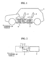
- a vehicle equipped with a fuel cell system of a first embodiment is comprised of a fuel cell stack 3, adapted to be supplied with hydrogen and air to generate electric power, and an under-floor fuel cell system casing 4 that accommodates therein a variety of mechanisms necessary for operating the fuel cell stack 3, both of which are disposed under a floor of a vehicle body 1, that is, below a vehicle floor panel, on which seats 2 are fixedly secured in a vehicle compartment.
- the fuel cell stack 3 has a structure that includes electric power generating cells overlapped in multiple stages in a way to allow an electrolyte-electrocatalyst composite body to be sandwiched between a fuel electrode, supplied with hydrogen, and an air electrode supplied with oxygen (air), thereby converting chemical energy into electrical energy through electrochemical reaction.
- the fuel electrode is supplied with hydrogen to dissociate hydrogen ions and electrons, which pass through the electrolyte and an external circuit, respectively, to generate electric power and move to the air electrode, respectively.
- the air electrode serves to react oxygen in supplied air with the hydrogen ions and the electrons to form water, which in turn is expelled to the outside.
- a solid polymer electrolyte is employed on consideration of a high energy density capability, reduction in costs and reduction in weight.
- the solid polymer electrolyte is comprised of an ion (proton) conductive polymer membrane such as an ion exchange membrane made of such as fluorocarbon resin.
- an ion (proton) conductive polymer membrane such as an ion exchange membrane made of such as fluorocarbon resin.
- the under-floor fuel cell system casing 4 internally accommodates various mechanisms, such as a fuel supply system that supplies hydrogen (or hydrogen rich gas) to the fuel cell stack 3 as fuel, an air supply system that supplies oxidant (air), a humidifying means that supplies pure water to the fuel cell stack 3 for humidification, and a cooling means for supplying the fuel cell stack 3. These various mechanisms serve to control operation of the fuel cell stack 3.
- the under floor fuel cell system casing 1 has an outer profile that is contoured along the shape of a lower surface of the vehicle floor panel in order to enable an under-floor space of the vehicle body 1 to be effectively utilized.
- the fuel cell system case 4 is installed on the under floor of the vehicle body 1 in close contact with the under floor of the vehicle body-floor panel.
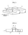
- the humidifying means that serves as a water supply device by which pure water is supplied to the fuel cell stack 3 for humidification.
- the other mechanisms such as the fuel supply system, are accommodated inside the under-floor fuel supply system case 4 as previously noted, the other mechanisms are omitted in FIG. 2.
- the humidifying means is comprised of a pump 6 for drawing pure water from a water storage tank 5 available to store pure water in a freezing state even at a temperature below the freezing point, a water delivery conduit 7 that forms a path through which pure water, drawn from the pump 6, is delivered to the fuel cell stack 3 (or the humidifier), and a water recovery conduit 8 through which water in excess is recovered from the fuel cell stack 3.
- the pump 6 draws pure water from the water storage tank 5 to be supplied to the fuel cell stack 3 through the water delivery conduit 7. Further, when operation of the fuel cell stack 3 is stopped, a whole of pure water inside the system is recovered to the water storage tank 5 in preparation for the freezing of pure water at the temperature below the freezing point.
- the component parts (including the pump 6, the water delivery conduit 7 and the water recovery conduit 8) of the humidifying means are disposed at a higher position than the water storage tank 5, e.g., in a position remotest from a road surface.
- an alternative structure may include application wherein the cooling means for cooling the fuel cell stack 3 takes the form of a structure to use pure water, stored in the water storage tank 5, as refrigerant and supply this pure water to the fuel cell stack 3 to cool the same. If the cooling means takes the form of such a structure, the cooling means serves as a water supply unit and, hence, component parts of such a cooling means are disposed above the water storage tank 5.
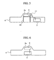
- the second illustrative embodiment contemplates to provide an arrangement wherein component parts of a water supply device are integrated as a water supply unit that is disposed in an embossed area, of an under-floor fuel cell system casing, that is embossed toward a vehicle compartment in conformity with a floor tunnel section of a vehicle body-floor panel.
- the vehicle body-floor panel there are many probabilities for the vehicle body-floor panel to be formed with a floor tunnel section with a shape embossed toward the vehicle compartment in a vicinity of a central area of the vehicle body-floor panel with a view to providing increased rigidity.
- the under-floor fuel cell system casing 4 When installing the under-floor fuel cell system casing 4 to the floor panel of the vehicle body in close contact to a lower surface thereof, the under-floor fuel cell system casing 4 is formed with an embossed section 4a that is embossed toward the vehicle compartment in conformity with the floor tunnel section of the vehicle body-floor panel as shown in FIG. 3.
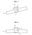
- the second illustrative embodiment contemplates to integrate the component parts of the water supply device into the water supply unit 9 and set up this water supply unit 9 in the embossed section 4a of the under-floor fuel cell system casing 4 as shown in FIG. 4. And, the water storage tank 5 is arranged to be disposed on the under-floor fuel cell system casing 4 in a wide space at a lower area. This results in arrangement in that the component parts of the water supply device assume higher positions than the water storage tank 5.
- the water supply unit 9 is disposed in the embossed section 4a of the under-floor fuel cell system casing 4 and there are less number of other component parts located on the same height as the water supply unit 9, it becomes possible to effectively utilize a space inside the embossed section 4a of the under-floor fuel cell system casing 4 for thereby permitting the component parts of the water supply device to be disposed in a coplanar relationship to provide a unitary structure. Accordingly, this results in a capability of providing a less vertical difference in a pure water flow path inside of the water supply unit 9 to provide a further ease of recovering pure water, enabling further reduction in residual pure water.
- the flow rate of pure water is less than that of refrigerant to be supplied to the fuel cell stack 3 and that of air to be used for reaction, and respective component parts of the water supply device are smaller in size and lighter in weight than those of component parts of the other system. Consequently, a structure in which these component parts are arranged to be located in an increasingly higher space within the under-floor fuel cell system casing 4 is more advantageous in structure than the other structure wherein heavy component parts of the other system are disposed, and is possible to compel a support structure 10 to be simplified in terms of G to be applied in back and force and from side to side.
- the second illustrative embodiment contemplates to locate the water supply unit 9 in a position easy for work to be done during maintenance under a circumstance where the fuel cell system is taken off from the vehicle body, resulting in improved maintenance workability.
- the second illustrative embodiment has the same fundamental structure as that of the second illustrative embodiment set forth above, the second illustrative embodiment features the provision of a work access opening 11 that is formed in the embossed section 4a of the under-floor fuel cell system casing 4 in correspondence with the setup position of the water supply unit 9, as shown in FIG. 5. Further, although illustration in the drawing is omitted, the floor tunnel section of the vehicle body-floor panel is formed with a similar work access opening at the same position as that in which the work access opening 11 is formed, with both of these work access openings mutually communicating each other.
- the water supply device it is probable for the water supply device to be provided with the ion removal filter and the foreign substance removal filter in order to decrease the electric conductivity of pure water and the foreign substances, and it is necessary to take a workability in replacement of these filters into consideration.
- the work access openings 11 for maintenance disposed in the embossed section 4a of the under-floor fuel cell system casing 4 and the floor tunnel section of the vehicle body-floor panel, it is possible to perform maintenance from the vehicle compartment. Accordingly, maintenance can be performed for replacement of the filters without taking off the fuel cell system from the vehicle body, resulting in remarkable improvement in workability during maintenance.
- a fourth illustrative embodiment has the same fundamental structure as that of the second illustrative embodiment set forth above and, in this illustrative embodiment, the water storage tank 5 is placed directly below the water supply unit 9 as shown in FIG. 6.
- a conduit connected between the water storage tank 5 and the water supply unit 9 results in a short length, enabling reduction in the amount of pure water inside the water supply device while enabling the water storage tank 5 to have a minimized capacity.
- this leads to reduction in weight of the under-floor fuel cell system casing 4 and, thus, reduction in weight of a whole of the vehicle equipped with the fuel cell system.
- the water storage tank 5 and the pump inside of the water supply unit 9 are placed to be closer to one another and the conduit between these component parts is shortened, providing improvement over the flow rate of pure water caused by the pump and controllability in pressure.
- the water storage tank 5 is located directly below the water supply unit 9 like in the fourth illustrative embodiment set forth above and, in this illustrative embodiment, the water storage tank 5 is integrated with the water supply unit 9 as shown in FIG. 8.
- the water storage tank 5 and the water supply unit 9 are integrated with one another, a whole of the water supply device, in which the water storage tank 5 is also included as the respective component parts forming the water supply unit 9, can be structured into one module, enabling further reduction in length of the delivery conduit of the water supply device and further miniaturization in each component part of the water storage tank 5 to be realized. Accordingly, the respective component parts and the delivery conduits of the water supply device can be arranged in a layout to enhance further efficient recovery of purer water, providing further improvement over a capability of recovering pure water. Also, another advantage includes remarkable reduction in the number of component parts, mass and costs.
- a sixth illustrative embodiment is described below in conjunction with a case where the under floor fuel cell system casing is formed with a second embossed section, that is embossed into a space that normally remains in no use inside the vehicle compartment, such as a dead space below a seat of the vehicle compartment and component parts of a humidifying means are located in the second embossed section.
- the second embossed section referred as 4b is formed on the under-floor fuel cell system casing 4 at an area below the seat 2.
- the vehicle floor panel of the vehicle body 1 is formed with an opening portion with a shape, corresponding to that of the second embossed section 4b, at a position below the seat 2 so as to allow the second embossed section 4b of the under-floor fuel cell system casing 4 to protrude through such an opening portion into a spacing below the seat 2 of the vehicle compartment.
- the component parts (forming the water supply unit 9) of the water supply device are disposed in the second embossed section 4b, and the water storage tank 5 is disposed below the water supply unit 9. This results in a layout wherein the component parts of the water supply device are disposed to assume a higher position than the water storage tank 5, providing further improvement over a water-recovering capability of the water supply device.
- the second embossed section 4b of the under-floor fuel cell system casing 4 protrudes into the vehicle compartment, since the area in which the second embossed section 4b protrudes into the vehicle compartment includes an area that is regarded as the dead space below the seat 2, there is no adverse affect on a space inside of the vehicle compartment. Moreover, it becomes possible to improve a working efficiency during maintenance such as replacement for the ion removal filter and the foreign substance removal filter. Also, the second emboss section 4b may be so structured to be covered with a cover that is detachable during a normal period whereas only during work for replacement, this cover is removed to achieve work for maintenance.
- the second embossed section 4b of the under-floor fuel cell system casing 4 is arranged to protrude into the area forming the dead space of the vehicle compartment and the component parts (forming the water supply unit 9) of the water supply device are disposed in the second embossed section 4b whereupon the water storage tank 5 is disposed below the water supply unit 9, a pure water recovering capability of the water supply device can be improved without causing an adverse affect on the spacing inside of the vehicle compartment while, accordingly, permitting the vehicle compartment to be kept in a free design of layout in the vehicle compartment.
Landscapes
- Engineering & Computer Science (AREA)
- Chemical & Material Sciences (AREA)
- General Chemical & Material Sciences (AREA)
- Combustion & Propulsion (AREA)
- Sustainable Energy (AREA)
- Manufacturing & Machinery (AREA)
- Chemical Kinetics & Catalysis (AREA)
- Electrochemistry (AREA)
- Life Sciences & Earth Sciences (AREA)
- Sustainable Development (AREA)
- Transportation (AREA)
- Mechanical Engineering (AREA)
- Fuel Cell (AREA)
- Electric Propulsion And Braking For Vehicles (AREA)
- Arrangement Or Mounting Of Propulsion Units For Vehicles (AREA)
- Cooling, Air Intake And Gas Exhaust, And Fuel Tank Arrangements In Propulsion Units (AREA)
Applications Claiming Priority (2)
| Application Number | Priority Date | Filing Date | Title |
|---|---|---|---|
| JP2003179557A JP4061589B2 (ja) | 2003-06-24 | 2003-06-24 | 燃料電池システム搭載車両 |
| JP2003179557 | 2003-06-24 |
Publications (3)
| Publication Number | Publication Date |
|---|---|
| EP1492188A2 true EP1492188A2 (fr) | 2004-12-29 |
| EP1492188A3 EP1492188A3 (fr) | 2008-06-25 |
| EP1492188B1 EP1492188B1 (fr) | 2015-07-22 |
Family
ID=33411058
Family Applications (1)
| Application Number | Title | Priority Date | Filing Date |
|---|---|---|---|
| EP04012130.3A Expired - Lifetime EP1492188B1 (fr) | 2003-06-24 | 2004-05-21 | Véhicule équipé d'un système de pile à combustible |
Country Status (3)
| Country | Link |
|---|---|
| US (1) | US7682715B2 (fr) |
| EP (1) | EP1492188B1 (fr) |
| JP (1) | JP4061589B2 (fr) |
Families Citing this family (13)
| Publication number | Priority date | Publication date | Assignee | Title |
|---|---|---|---|---|
| EP1717083B1 (fr) * | 2002-06-10 | 2008-12-10 | Toyota Jidosha Kabushiki Kaisha | Véhicule à pile à combustible |
| US20050179242A1 (en) * | 2004-02-03 | 2005-08-18 | Chernoff Adrian B. | Vehicle front seat configuration |
| JP3991283B2 (ja) * | 2004-10-05 | 2007-10-17 | 松下電器産業株式会社 | 高分子電解質膜電極接合体の保管方法 |
| JP4727323B2 (ja) * | 2005-07-08 | 2011-07-20 | 本田技研工業株式会社 | 燃料電池自動車構造 |
| AU2006201027B2 (en) * | 2005-08-02 | 2011-01-06 | Hy-Drive Technologies Ltd. | Hydrogen generating apparatus |
| JP5024588B2 (ja) * | 2005-12-12 | 2012-09-12 | トヨタ自動車株式会社 | 燃料電池車両 |
| JP2008288027A (ja) * | 2007-05-17 | 2008-11-27 | Toyota Motor Corp | 燃料電池システム及び燃料電池車両 |
| JP2009218039A (ja) * | 2008-03-10 | 2009-09-24 | Hitachi Ltd | 燃料電池システム |
| JP5308292B2 (ja) * | 2009-09-25 | 2013-10-09 | 本田技研工業株式会社 | 燃料電池車両 |
| DE112010005562T8 (de) * | 2010-05-13 | 2013-05-29 | Toyota Jidosha Kabushiki Kaisha | Brennstoffzellensystem für ein Fahrzeug und Brennstoffzellenfahrzeug |
| US8936220B2 (en) * | 2011-12-08 | 2015-01-20 | GM Global Technology Operations LLC | Integrated shaped plastic exhaust system for fuel cell vehicles |
| DE102019203249A1 (de) * | 2019-03-11 | 2020-09-17 | Audi Ag | Brennstoffzellenaufbau, Brennstoffzellensystem und Brennstoffzellenfahrzeug |
| FR3115237B1 (fr) * | 2020-10-16 | 2024-10-11 | Renault Sas | Véhicule comprenant une batterie électrique et un circuit de refroidissement de celle-ci |
Citations (3)
| Publication number | Priority date | Publication date | Assignee | Title |
|---|---|---|---|---|
| JP2000257430A (ja) | 1999-03-04 | 2000-09-19 | Toyota Motor Corp | 内燃機関の冷却装置 |
| JP2001268720A (ja) | 2000-03-17 | 2001-09-28 | Equos Research Co Ltd | 燃料電池搭載車両 |
| JP2002158024A (ja) | 2000-08-03 | 2002-05-31 | General Motors Corp <Gm> | 電気化学エンジンのための水管理システム |
Family Cites Families (12)
| Publication number | Priority date | Publication date | Assignee | Title |
|---|---|---|---|---|
| JP3433064B2 (ja) * | 1997-10-01 | 2003-08-04 | 本田技研工業株式会社 | 自動車のフロア構造 |
| US6464854B2 (en) * | 1997-12-16 | 2002-10-15 | Lynntech, Inc. | Water sources for automotive electrolyzers |
| DE20108808U1 (de) * | 2000-06-05 | 2001-08-23 | ATECS Mannesmann AG, 40213 Düsseldorf | Brennstoffzellensystem mit einem einen temperaturgeregelten Flüssigkeitsablaß aufweisenden Flüssigkeitsbehälter |
| US6887601B2 (en) * | 2000-09-28 | 2005-05-03 | Proton Energy Systems, Inc. | Regenerative electrochemical cell system and method for use thereof |
| JP3722019B2 (ja) * | 2001-06-27 | 2005-11-30 | 日産自動車株式会社 | 燃料電池システム |
| US6562503B2 (en) * | 2001-08-22 | 2003-05-13 | Utc Fuel Cells, Llc | Freeze tolerant fuel cell power plant |
| US6727013B2 (en) * | 2001-09-07 | 2004-04-27 | General Motors Corporation | Fuel cell energy management system for cold environments |
| JP3932185B2 (ja) * | 2001-09-26 | 2007-06-20 | 本田技研工業株式会社 | 燃料電池搭載型電気自動車および燃料電池システムボックス |
| DE10148113A1 (de) * | 2001-09-28 | 2003-04-30 | Daimler Chrysler Ag | Fahrzeug mit einem Energiespeicher und Verfahren zum Betreiben des Fahrzeugs |
| US20050139402A1 (en) * | 2002-08-27 | 2005-06-30 | Masayoshi Yamashita | Fuel cell vehicle |
| JP2004122972A (ja) * | 2002-10-03 | 2004-04-22 | Toyota Motor Corp | 自動車 |
| JP4178986B2 (ja) * | 2003-02-13 | 2008-11-12 | トヨタ自動車株式会社 | 車両用電気機器の搭載構造 |
-
2003
- 2003-06-24 JP JP2003179557A patent/JP4061589B2/ja not_active Expired - Fee Related
-
2004
- 2004-05-21 EP EP04012130.3A patent/EP1492188B1/fr not_active Expired - Lifetime
- 2004-05-26 US US10/853,758 patent/US7682715B2/en not_active Expired - Fee Related
Patent Citations (4)
| Publication number | Priority date | Publication date | Assignee | Title |
|---|---|---|---|---|
| JP2000257430A (ja) | 1999-03-04 | 2000-09-19 | Toyota Motor Corp | 内燃機関の冷却装置 |
| JP2001268720A (ja) | 2000-03-17 | 2001-09-28 | Equos Research Co Ltd | 燃料電池搭載車両 |
| JP2002158024A (ja) | 2000-08-03 | 2002-05-31 | General Motors Corp <Gm> | 電気化学エンジンのための水管理システム |
| US6432568B1 (en) | 2000-08-03 | 2002-08-13 | General Motors Corporation | Water management system for electrochemical engine |
Also Published As
| Publication number | Publication date |
|---|---|
| US20040262059A1 (en) | 2004-12-30 |
| JP2005014666A (ja) | 2005-01-20 |
| JP4061589B2 (ja) | 2008-03-19 |
| EP1492188A3 (fr) | 2008-06-25 |
| US7682715B2 (en) | 2010-03-23 |
| EP1492188B1 (fr) | 2015-07-22 |
Similar Documents
| Publication | Publication Date | Title |
|---|---|---|
| US9079508B2 (en) | Fuel cell vehicle | |
| JP5965423B2 (ja) | 燃料電池車両 | |
| US7682715B2 (en) | Vehicle equipped with fuel cell system | |
| US9147897B2 (en) | In-vehicle fuel cell system | |
| KR20080067018A (ko) | 연료전지, 연료전지를 이용한 전력공급방법, 기능카드,연료전지의 기체공급기구, 발전체 및 발전체의 제조방법 | |
| JP4887639B2 (ja) | セパレータユニット及び燃料電池スタック | |
| JP2008243513A (ja) | 集電体、その製造方法及び燃料電池 | |
| JP2009224180A (ja) | 集電体及び燃料電池 | |
| JP2011204500A (ja) | 燃料電池システム | |
| JP4770137B2 (ja) | 燃料電池システム及びその運転方法 | |
| JP2008243572A (ja) | 集電体及び燃料電池 | |
| JP2007066625A (ja) | 燃料電池スタック | |
| JP2011150940A (ja) | 燃料電池システム | |
| JP5474606B2 (ja) | 車載用燃料電池スタック | |
| JP5011749B2 (ja) | 燃料電池装置 | |
| JP2006032363A (ja) | 燃料電池、機能カード、燃料電池の気体供給機構、発電体及び発電体の製造方法 | |
| JP4599927B2 (ja) | 燃料電池システム及びその運転方法 | |
| JP2007227278A (ja) | 燃料電池装置 | |
| KR100533008B1 (ko) | 물포집장치를 가지는 연료전지 시스템 | |
| JP5142176B2 (ja) | 固体高分子型燃料電池システム | |
| JP2008171660A (ja) | 燃料電池システム | |
| JP2008166052A (ja) | 水浄化装置及びそれを有する燃料電池システム | |
| JP2006253036A (ja) | セパレータユニット及び燃料電池スタック | |
| JP4507971B2 (ja) | 燃料電池装置 | |
| JP5019719B2 (ja) | セパレータユニット |
Legal Events
| Date | Code | Title | Description |
|---|---|---|---|
| PUAI | Public reference made under article 153(3) epc to a published international application that has entered the european phase |
Free format text: ORIGINAL CODE: 0009012 |
|
| 17P | Request for examination filed |
Effective date: 20040521 |
|
| AK | Designated contracting states |
Kind code of ref document: A2 Designated state(s): AT BE BG CH CY CZ DE DK EE ES FI FR GB GR HU IE IT LI LU MC NL PL PT RO SE SI SK TR |
|
| AX | Request for extension of the european patent |
Extension state: AL HR LT LV MK |
|
| PUAL | Search report despatched |
Free format text: ORIGINAL CODE: 0009013 |
|
| AK | Designated contracting states |
Kind code of ref document: A3 Designated state(s): AT BE BG CH CY CZ DE DK EE ES FI FR GB GR HU IE IT LI LU MC NL PL PT RO SE SI SK TR |
|
| AX | Request for extension of the european patent |
Extension state: AL HR LT LV MK |
|
| AKX | Designation fees paid |
Designated state(s): DE FR GB |
|
| 17Q | First examination report despatched |
Effective date: 20090706 |
|
| GRAP | Despatch of communication of intention to grant a patent |
Free format text: ORIGINAL CODE: EPIDOSNIGR1 |
|
| INTG | Intention to grant announced |
Effective date: 20150424 |
|
| GRAS | Grant fee paid |
Free format text: ORIGINAL CODE: EPIDOSNIGR3 |
|
| GRAA | (expected) grant |
Free format text: ORIGINAL CODE: 0009210 |
|
| AK | Designated contracting states |
Kind code of ref document: B1 Designated state(s): DE FR GB |
|
| REG | Reference to a national code |
Ref country code: GB Ref legal event code: FG4D |
|
| REG | Reference to a national code |
Ref country code: DE Ref legal event code: R096 Ref document number: 602004047525 Country of ref document: DE |
|
| REG | Reference to a national code |
Ref country code: DE Ref legal event code: R097 Ref document number: 602004047525 Country of ref document: DE |
|
| PLBE | No opposition filed within time limit |
Free format text: ORIGINAL CODE: 0009261 |
|
| STAA | Information on the status of an ep patent application or granted ep patent |
Free format text: STATUS: NO OPPOSITION FILED WITHIN TIME LIMIT |
|
| 26N | No opposition filed |
Effective date: 20160425 |
|
| REG | Reference to a national code |
Ref country code: DE Ref legal event code: R119 Ref document number: 602004047525 Country of ref document: DE |
|
| GBPC | Gb: european patent ceased through non-payment of renewal fee |
Effective date: 20160521 |
|
| REG | Reference to a national code |
Ref country code: FR Ref legal event code: ST Effective date: 20170131 |
|
| PG25 | Lapsed in a contracting state [announced via postgrant information from national office to epo] |
Ref country code: DE Free format text: LAPSE BECAUSE OF NON-PAYMENT OF DUE FEES Effective date: 20161201 Ref country code: FR Free format text: LAPSE BECAUSE OF NON-PAYMENT OF DUE FEES Effective date: 20160531 |
|
| PG25 | Lapsed in a contracting state [announced via postgrant information from national office to epo] |
Ref country code: GB Free format text: LAPSE BECAUSE OF NON-PAYMENT OF DUE FEES Effective date: 20160521 |