EP1492384A2 - Dispositif de chauffage électrique, utilisé en particulier pour des véhicules - Google Patents
Dispositif de chauffage électrique, utilisé en particulier pour des véhicules Download PDFInfo
- Publication number
- EP1492384A2 EP1492384A2 EP04016205A EP04016205A EP1492384A2 EP 1492384 A2 EP1492384 A2 EP 1492384A2 EP 04016205 A EP04016205 A EP 04016205A EP 04016205 A EP04016205 A EP 04016205A EP 1492384 A2 EP1492384 A2 EP 1492384A2
- Authority
- EP
- European Patent Office
- Prior art keywords
- heating
- control device
- frame
- heating device
- heating elements
- Prior art date
- Legal status (The legal status is an assumption and is not a legal conclusion. Google has not performed a legal analysis and makes no representation as to the accuracy of the status listed.)
- Granted
Links
Images

Classifications
-
- B—PERFORMING OPERATIONS; TRANSPORTING
- B60—VEHICLES IN GENERAL
- B60H—ARRANGEMENTS OF HEATING, COOLING, VENTILATING OR OTHER AIR-TREATING DEVICES SPECIALLY ADAPTED FOR PASSENGER OR GOODS SPACES OF VEHICLES
- B60H1/00—Heating, cooling or ventilating devices
- B60H1/22—Heating, cooling or ventilating devices the heat source being other than the propulsion plant
- B60H1/2215—Heating, cooling or ventilating devices the heat source being other than the propulsion plant the heat being derived from electric heaters
- B60H1/2218—Heating, cooling or ventilating devices the heat source being other than the propulsion plant the heat being derived from electric heaters controlling the operation of electric heaters
-
- B—PERFORMING OPERATIONS; TRANSPORTING
- B60—VEHICLES IN GENERAL
- B60H—ARRANGEMENTS OF HEATING, COOLING, VENTILATING OR OTHER AIR-TREATING DEVICES SPECIALLY ADAPTED FOR PASSENGER OR GOODS SPACES OF VEHICLES
- B60H1/00—Heating, cooling or ventilating devices
- B60H1/22—Heating, cooling or ventilating devices the heat source being other than the propulsion plant
- B60H1/2215—Heating, cooling or ventilating devices the heat source being other than the propulsion plant the heat being derived from electric heaters
- B60H1/2225—Heating, cooling or ventilating devices the heat source being other than the propulsion plant the heat being derived from electric heaters arrangements of electric heaters for heating air
-
- F—MECHANICAL ENGINEERING; LIGHTING; HEATING; WEAPONS; BLASTING
- F24—HEATING; RANGES; VENTILATING
- F24H—FLUID HEATERS, e.g. WATER OR AIR HEATERS, HAVING HEAT-GENERATING MEANS, e.g. HEAT PUMPS, IN GENERAL
- F24H3/00—Air heaters
- F24H3/02—Air heaters with forced circulation
- F24H3/04—Air heaters with forced circulation the air being in direct contact with the heating medium, e.g. electric heating element
- F24H3/0405—Air heaters with forced circulation the air being in direct contact with the heating medium, e.g. electric heating element using electric energy supply, e.g. the heating medium being a resistive element; Heating by direct contact, i.e. with resistive elements, electrodes and fins being bonded together without additional element in-between
- F24H3/0429—For vehicles
-
- F—MECHANICAL ENGINEERING; LIGHTING; HEATING; WEAPONS; BLASTING
- F24—HEATING; RANGES; VENTILATING
- F24H—FLUID HEATERS, e.g. WATER OR AIR HEATERS, HAVING HEAT-GENERATING MEANS, e.g. HEAT PUMPS, IN GENERAL
- F24H9/00—Details
- F24H9/18—Arrangement or mounting of grates or heating means
- F24H9/1854—Arrangement or mounting of grates or heating means for air heaters
- F24H9/1863—Arrangement or mounting of electric heating means
- F24H9/1872—PTC resistor
-
- H—ELECTRICITY
- H05—ELECTRIC TECHNIQUES NOT OTHERWISE PROVIDED FOR
- H05B—ELECTRIC HEATING; ELECTRIC LIGHT SOURCES NOT OTHERWISE PROVIDED FOR; CIRCUIT ARRANGEMENTS FOR ELECTRIC LIGHT SOURCES, IN GENERAL
- H05B3/00—Ohmic-resistance heating
- H05B3/10—Heating elements characterised by the composition or nature of the materials or by the arrangement of the conductor
- H05B3/12—Heating elements characterised by the composition or nature of the materials or by the arrangement of the conductor characterised by the composition or nature of the conductive material
- H05B3/14—Heating elements characterised by the composition or nature of the materials or by the arrangement of the conductor characterised by the composition or nature of the conductive material the material being non-metallic
-
- H—ELECTRICITY
- H05—ELECTRIC TECHNIQUES NOT OTHERWISE PROVIDED FOR
- H05B—ELECTRIC HEATING; ELECTRIC LIGHT SOURCES NOT OTHERWISE PROVIDED FOR; CIRCUIT ARRANGEMENTS FOR ELECTRIC LIGHT SOURCES, IN GENERAL
- H05B3/00—Ohmic-resistance heating
- H05B3/40—Heating elements having the shape of rods or tubes
- H05B3/42—Heating elements having the shape of rods or tubes non-flexible
- H05B3/48—Heating elements having the shape of rods or tubes non-flexible heating conductor embedded in insulating material
- H05B3/50—Heating elements having the shape of rods or tubes non-flexible heating conductor embedded in insulating material heating conductor arranged in metal tubes, the radiating surface having heat-conducting fins
-
- H—ELECTRICITY
- H05—ELECTRIC TECHNIQUES NOT OTHERWISE PROVIDED FOR
- H05B—ELECTRIC HEATING; ELECTRIC LIGHT SOURCES NOT OTHERWISE PROVIDED FOR; CIRCUIT ARRANGEMENTS FOR ELECTRIC LIGHT SOURCES, IN GENERAL
- H05B2203/00—Aspects relating to Ohmic resistive heating covered by group H05B3/00
- H05B2203/02—Heaters using heating elements having a positive temperature coefficient
Definitions
- the invention relates to an electrical heating device, in particular for a motor vehicle, according to the preamble of patent claim 1.
- the heating of the vehicle interior in motor vehicles is usually carried out by means of the cooling water of the drive unit, so that the heat generated in the engine via a heat exchanger, if necessary, is delivered to the air flowing into the vehicle interior.
- this heat is available only after a certain period of operation, so that especially in the cold season, the effect of the heating is perceived as insufficient.
- a vehicle manufactured by Audi AG called “A6” includes an electric booster heater having a plurality of heating elements assembled to a heating block, wherein the heating block is held in a frame. Individual or group of heating elements can be switched on and off separately. Since a high current must be switched at high heating power due to the low on-board voltage, switching relays are used for switching. In the vehicle “Audi A6" two such relays are provided so that the heater can operate in three power levels.
- each separately switchable heating element or each separately switchable heating element group must be connected to a relay via one electrical line, whereby a large amount of wiring is necessary. Furthermore, each line must be secured individually. Next claim the relays a certain amount of space.
- Another disadvantage is that the control of the relay is carried out by a control device, which in turn is arranged at another location in the motor vehicle, for example in the engine electronics, on-board computer or in the electronics of a control unit of a heating or air conditioning. This further increases the cabling effort. With this known heater only three heating power stages are switchable. Since the heating power can be switched in only three stages, the heating power can only be insufficiently adapted to the maximum electrical power currently available from the electrical system.
- the control device forms a structural unit with the heating block held in the frame.
- all cabling between the control device and the heating block can be omitted.
- the safeguarding of individual lines by fuses is also eliminated. It is only needed a fuse in the common voltage supply to the electric heater.
- the control device forms part of the electrical heating device
- the heating elements or heating element groups are activated via individual electronic switches.
- the otherwise customary switching relays can thereby be dispensed with, as a result of which installation space, in particular outside a heating or air-conditioning system having the heating device according to the invention, is saved.
- significantly more heating elements or heating element groups can be controlled separately, as more electronic switches can be accommodated due to their small footprint in the power electronics as switching relays place.
- the heating device according to the invention is therefore better controlled and can be controlled to a significantly larger number of power levels. As a result, the switchable heating power is close to the maximum available power from the electrical system adaptable.
- the control device is preferably divided into a drive logic and a power electronics, wherein the power electronics includes the electronic switches.
- control device to a data bus system, such as CAN, or a serial interface can be connected via the or the corresponding Control commands are passed to the control logic of the control device.
- a data bus system such as CAN
- serial interface can be connected via the or the corresponding Control commands are passed to the control logic of the control device.
- the heating device according to the invention can be connected directly to the vehicle battery without additional isolation relay.
- the electronic switch heatsink which are arranged in the control device such that they are acted upon by the air flow to be heated, which flows through the heater, so that the air flow is not only warmed up, but at the same time for cooling the electronic switch and so that the control device can be used.
- the power loss of the control device is supplied to the air flow to be heated.
- control device In order to replace the control device, it is preferably via electrical connections to the heating block plugged.
- control device is arranged laterally on the frame so that the main part of the air flow can pass through the heating device and only one edge part of the air flow flows to the control device for cooling.
- the frame is made of plastic and has guides in which the control device for installation and removal is feasible, so that, for example, the attachment of the control device is facilitated to the heating block and the control device is held on the frame.
- the frame may be made of metal and the control device integrated in the frame.
- control device can be used to monitor the electrical heating elements and / or the control device itself, wherein preferably the monitoring data via the data bus system or the serial interface are available.
- control device can be used to protect the electrical heating elements and / or the control device itself against electrical and / or thermal overload.
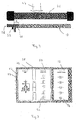
- a heating device 10 which is shown in the drawing, has a heating block (not shown in more detail and only indicated in sections at 12), which is formed from individual heating elements 14 and corrugated fins 16 arranged between the heating elements.
- a heating block (not shown in more detail and only indicated in sections at 12), which is formed from individual heating elements 14 and corrugated fins 16 arranged between the heating elements.
- Such heating elements 14 are described for example in DE 44 36 613 and there are preferably held between two sheets PTC heating elements. Alternatively, the heating elements could also be formed as corrugated fins formed as electrical heating resistors.
- the heating block 12 is held in a frame 18 which is preferably made of plastic or metal. In the embodiment shown in Fig. 1 the frame 18 consists of two frame halves 20 and 22, which are held together with brackets 24.
- the individual heating elements 14 of the heating block 12 are electrically isolated from each other and from the frame 18.
- a control device 28 is provided, which forms a structural unit together with the held in the frame 18 heating block 12, as shown in Fig. 1 .
- the control device 28 is preferably designed as a plug-in module and directly to a front frame leg 30, not shown electrical connections for the heating elements 14, attachable.
- the electrical connections are passed through recesses 32 in the front frame leg 30, so that the control device 28 is infected substantially directly to the heating elements 14 of the heating block 12.
- To facilitate insertion and removal of the control device 28 are parallel frame legs 34 and 36 on the front frame leg 30 and have guide grooves formed as guides 38, in which the control device 28 via corresponding guide lugs or webs in Ansteckraum can be guided.
- the guides 38 serve to hold the control device 28 on the frame 18.
- the control device 28 preferably extends substantially the full length of the side 26.
- the control device 28 has electronic components, such as electronic switches such as power transistors 52 or the like., For switching on and off of the individual heating elements 14, on. In the illustration of FIG. 1 , retaining clips 40 for the power transistors can be seen.
- the high-performance electronic components, such as the power transistors, are connected to heatsinks for cooling.
- the heat sinks 42 are preferably arranged in the immediate vicinity of the front frame leg 30, so that the heat sinks 42 are acted upon by the air flow to be heated, which is indicated by an arrow 44 ( FIG. 2 ).
- the heater 10 which is seen downstream of a heat exchanger 46, for example, downstream in the flow direction 44, arranged such that the control device 28 with the front frame leg 30 to a Distance a projects laterally into the air flow (FIG. 2).
- the air flow 44 to be heated is simultaneously used for cooling the electronic components and additionally heated by the waste heat of the electronic components.
- the control device 28 has a drive logic 48 and a power electronics 50. Via the individual electronic switches 52, which are cooled by the heat sinks 42, the heating elements 14 or heating element groups are separately switchable. Each heating element 14 or heating element group is preferably assigned an electronic switch, for example a power transistor 52.
- the control logic 48 which includes the algorithm for driving the individual heating elements 14 or groups of heating elements, may be integrated into the control device 28 so that the control logic 48 and the power electronics 50 can form a unit. All required for the control of the heating power signal inputs 54 can be supplied via a serial interface or a data bus system, such as CAN.
- a compact electric heater which only has a bus connection in addition to power supply lines.
- the corresponding electrical leads are shown in FIG. 1 at 56, 58 and 60.
- the supply line for the heating elements 14 in one of the projecting frame legs 34 or 36 is arranged.
- the data bus terminal 60 is supplied directly to the controller 28.
- the heating power can be adjusted as needed in a simple manner by connecting or disconnecting individual heating elements 14 or heating element groups. Due to the consequent switching smaller current levels result in lower voltage dips or voltage overshoot when switching on or off of individual heating elements, whereby the electrical system load is made uniform. This results in lower torque changes on the generator and a relief of the engine idle speed control. Due to the smaller power level, the switched-on heating power can be better suited to the maximum standing power of the generator to be adjusted. Furthermore, via the individually controllable heating elements 14, a temperature distribution over the surface of the heating block 12 can be achieved, or a non-uniform temperature distribution can be made uniform. Defective heating elements can be switched off, so that the electric heater 10 does not have to be replaced immediately in the event of a defect.
Landscapes
- Engineering & Computer Science (AREA)
- Physics & Mathematics (AREA)
- Thermal Sciences (AREA)
- Mechanical Engineering (AREA)
- Chemical & Material Sciences (AREA)
- Combustion & Propulsion (AREA)
- General Engineering & Computer Science (AREA)
- Air-Conditioning For Vehicles (AREA)
Applications Claiming Priority (3)
| Application Number | Priority Date | Filing Date | Title |
|---|---|---|---|
| DE19738318.1A DE19738318C5 (de) | 1997-09-02 | 1997-09-02 | Elektrische Heizeinrichtung für ein Kraftfahrzeug |
| DE19738318 | 1997-09-02 | ||
| EP98110528A EP0901311B1 (fr) | 1997-09-02 | 1998-06-09 | Appareil de chauffage électrique pour véhicule |
Related Parent Applications (2)
| Application Number | Title | Priority Date | Filing Date |
|---|---|---|---|
| EP98110528A Division EP0901311B1 (fr) | 1997-09-02 | 1998-06-09 | Appareil de chauffage électrique pour véhicule |
| EP98110528.1 Division | 1998-06-09 |
Publications (3)
| Publication Number | Publication Date |
|---|---|
| EP1492384A2 true EP1492384A2 (fr) | 2004-12-29 |
| EP1492384A3 EP1492384A3 (fr) | 2005-12-07 |
| EP1492384B1 EP1492384B1 (fr) | 2007-09-26 |
Family
ID=7840960
Family Applications (3)
| Application Number | Title | Priority Date | Filing Date |
|---|---|---|---|
| EP05003106.1A Expired - Lifetime EP1530405B1 (fr) | 1997-09-02 | 1998-06-09 | Dispositif de chauffage électrique, particulièrement pour véhicules automobiles. |
| EP98110528A Expired - Lifetime EP0901311B1 (fr) | 1997-09-02 | 1998-06-09 | Appareil de chauffage électrique pour véhicule |
| EP04016205A Revoked EP1492384B1 (fr) | 1997-09-02 | 1998-06-09 | Dispositif de chauffage électrique, utilisé en particulier pour des véhicules |
Family Applications Before (2)
| Application Number | Title | Priority Date | Filing Date |
|---|---|---|---|
| EP05003106.1A Expired - Lifetime EP1530405B1 (fr) | 1997-09-02 | 1998-06-09 | Dispositif de chauffage électrique, particulièrement pour véhicules automobiles. |
| EP98110528A Expired - Lifetime EP0901311B1 (fr) | 1997-09-02 | 1998-06-09 | Appareil de chauffage électrique pour véhicule |
Country Status (3)
| Country | Link |
|---|---|
| EP (3) | EP1530405B1 (fr) |
| DE (3) | DE19738318C5 (fr) |
| ES (2) | ES2294402T3 (fr) |
Cited By (1)
| Publication number | Priority date | Publication date | Assignee | Title |
|---|---|---|---|---|
| EP1691579A1 (fr) * | 2005-02-09 | 2006-08-16 | Catem GmbH & Co. KG | Dispositif de chauffage électrique, en particulier pour véhicule à moteur |
Families Citing this family (43)
| Publication number | Priority date | Publication date | Assignee | Title |
|---|---|---|---|---|
| DE19918906C2 (de) * | 1999-04-26 | 2003-07-17 | Valeo Klimasysteme Gmbh | PTC-Heizregister |
| DE19964535B4 (de) | 1999-06-05 | 2019-09-05 | Mahle International Gmbh | Heizeinrichtung, insbesondere für ein Kraftfahrzeug |
| DE19925757C5 (de) * | 1999-06-05 | 2011-02-10 | Behr France Rouffach S.A.S. | Heizeinrichtung, insbesondere für ein Kraftfahrzeug |
| DE19933013A1 (de) * | 1999-07-14 | 2001-02-01 | Valeo Klimasysteme Gmbh | PTC-Heizelement mit Heizzonen |
| DE19957452B4 (de) * | 1999-11-19 | 2019-03-28 | Mahle International Gmbh | Elektrische Heizeinrichtung, insbesondere für ein Kraftfahrzeug |
| ES2170017B2 (es) * | 1999-11-19 | 2003-08-01 | Behr France Sarl | Instalacion de calefaccion electrica, particularmente para un vehiculo automovil. |
| DE10015905B4 (de) * | 2000-03-30 | 2010-02-18 | Fritz Eichenauer Gmbh & Co. Kg | Vorrichtung zur Beheizung von Innenräumen von Kraftfahrzeugen |
| ES2187411T3 (es) | 2000-05-23 | 2003-06-16 | Catem Gmbh & Co Kg | Dispositivo calefactor electrico, especialmente para la aplicacion en automoviles. |
| DE10028446B4 (de) * | 2000-06-14 | 2006-03-30 | Beru Ag | Elektrische Zusatzheizeinrichtung |
| DE10049030B4 (de) * | 2000-10-04 | 2013-04-04 | Behr Gmbh & Co. Kg | Heizkörperblock |
| DE10061458B4 (de) * | 2000-12-09 | 2005-12-15 | Eichenauer Heizelemente Gmbh & Co. Kg | Verfahren und Vorrichtung zum Regeln einer Kfz-Zusatzheizung |
| DE10141146B4 (de) * | 2001-08-22 | 2020-04-30 | Valeo Klimasysteme Gmbh | PTC-Heizvorrichtung |
| DE10142512B4 (de) * | 2001-08-30 | 2006-04-06 | Daimlerchrysler Ag | Elektrische Heizvorrichtung für Kraftfahrzeuge |
| KR100478966B1 (ko) * | 2001-11-27 | 2005-03-25 | 카템 게엠베하 운트 캄파니 카게 | 자동차용 보조전기가열장치 |
| DE10213407A1 (de) * | 2002-03-26 | 2003-10-09 | Behr Gmbh & Co | Heizkörper und Verfahren zur Steuerung eines Heizkörpers, insbesondere für ein Kraftfahrzeug |
| DE10216010A1 (de) * | 2002-04-11 | 2003-10-23 | Behr France Sarl | Elektrische Heizvorrichtung, insbesondere für ein Kraftfahrzeug |
| FR2838599B1 (fr) * | 2002-04-11 | 2004-08-06 | Valeo Climatisation | Dispositif de chauffage electrique, notamment pour appareil de chauffage et ou climatisation de vehicule |
| DE50213799D1 (de) | 2002-09-02 | 2009-10-08 | Eberspaecher Catem Gmbh & Co K | Elektrische Heizung für Kraftfahrzeuge |
| FR2849806B1 (fr) * | 2003-01-10 | 2006-03-17 | Valeo Climatisation | Dispositif de chauffage pour vehicule automobile |
| EP1486363B1 (fr) * | 2003-06-13 | 2007-08-15 | Behr France Rouffach SAS | Dispositif de chauffage comprenant un élément ptc, en particulier pour véhicule |
| EP1502784B2 (fr) * | 2003-07-31 | 2010-09-15 | Behr France Rouffach SAS | Dispositif de chauffage électrique |
| FR2859349B1 (fr) * | 2003-08-29 | 2006-12-01 | Valeo Climatisation | Element de chauffage electrique pour appareil de ventilation, de chauffage et/ou de climatisation d'habitacle |
| EP1681457B2 (fr) † | 2003-10-08 | 2017-04-19 | Nagares, S.A. | Module chauffant des gaz d'admission d'un moteur d'automobile a commande electronique de la temperature integree |
| EP1580050B1 (fr) | 2004-03-26 | 2013-02-27 | Behr GmbH & Co. KG | Appareil de chauffage auxiliaire électrique, en particulier pour véhicules |
| ATE380695T1 (de) * | 2004-10-29 | 2007-12-15 | Behr France Rouffach Sas | Elektrische heizungsanordnung, inbesondere für ein kraftfahrzeug |
| ATE430049T1 (de) † | 2004-10-29 | 2009-05-15 | Behr France Rouffach Sas | Elektrische heizungsanordnung für ein kraftfahrzeug |
| FR2878316B1 (fr) * | 2004-11-25 | 2007-03-16 | Valeo Climatisation Sa | Dispositif de chauffage electrique, notamment pour appareil de chauffage, de ventilation et/ou de climatisation de vehicule |
| EP1747920B2 (fr) | 2005-07-26 | 2018-07-11 | Mahle Behr France Rouffach S.A.S | Générateur de chaleur à coefficient de température positif (CTP) pour véhicule |
| FR2897744B1 (fr) * | 2006-02-17 | 2008-05-09 | Valeo Systemes Thermiques | Chassis porteur d'elements chauffants pour un radiateur electrique d'une installation de ventilation, de chauffage et/ou de climatisation. |
| FR2916933B1 (fr) * | 2007-06-01 | 2009-09-04 | Valeo Systemes Thermiques | Dispositif de connexion electrique entre une source d'alimentation electrique et un radiateur electrique, et procede de realisation d'un tel dispositif de connexion |
| FR2922817B1 (fr) | 2007-10-31 | 2012-12-21 | Valeo Systemes Thermiques | Dispositif de chauffage electrique d'un flux d'air circulant a l'interieur d'une installation de ventilation, de chauffage et/ou de climatisation d'un vehicule automobile |
| EP2315493B1 (fr) * | 2009-10-21 | 2017-05-10 | Mahle Behr France Rouffach S.A.S | Dispositif de chauffage notamment pour une climatisation de véhicule automobile |
| EP2440005B1 (fr) | 2010-10-08 | 2015-12-23 | Eberspächer catem GmbH & Co. KG | Dispositif de chauffage électrique et son procédé de fabrication |
| DE102011007817A1 (de) * | 2011-04-20 | 2012-10-25 | Webasto Ag | Elektrische Heizung, Fahrzeug mit elektrischer Heizung sowie Verfahren zum Steuern einer elektrischen Heizung |
| EP2607121B2 (fr) * | 2011-12-22 | 2020-07-08 | Eberspächer catem GmbH & Co. KG | Dispositif de chauffage électrique, en particulier pour un véhicule automobile |
| DE102012025445A1 (de) | 2011-12-22 | 2013-06-27 | Eberspächer Catem Gmbh & Co. Kg | Elektrische Heizvorrichtung |
| EP2884817B1 (fr) | 2013-12-13 | 2017-08-30 | Eberspächer catem GmbH & Co. KG | Dispositif de chauffage électrique et son procédé de fabrication |
| EP2897230B1 (fr) | 2014-01-21 | 2019-05-15 | Eberspächer catem GmbH & Co. KG | Connection électrique notamment pour un système de chauffage d'un véhicule |
| EP3096587B1 (fr) | 2015-05-20 | 2019-07-17 | MAHLE International GmbH | Dispositif de chauffage électrique |
| DE102016224296A1 (de) | 2016-12-06 | 2018-06-07 | Eberspächer Catem Gmbh & Co. Kg | Elektrische heizvorrichtung |
| FR3072614B1 (fr) * | 2017-10-24 | 2020-02-07 | Valeo Systemes Thermiques | Dispositif de chauffage, et boitier de climatisation d'un vehicule automobile equipe d'un tel dispositif |
| FR3075327B1 (fr) * | 2017-12-19 | 2020-05-15 | Valeo Systemes Thermiques | Module d'alimentation pour radiateur de chauffage et radiateur de chauffage equipe d'un tel module |
| DE102021104371A1 (de) | 2021-02-24 | 2022-08-25 | Audi Aktiengesellschaft | Kraftfahrzeug und Verfahren zur Anpassung einer verfügbaren Heizleistung in einem Kraftfahrzeug |
Citations (3)
| Publication number | Priority date | Publication date | Assignee | Title |
|---|---|---|---|---|
| DE2724269C2 (de) | 1977-05-28 | 1982-02-11 | Süddeutsche Kühlerfabrik Julius Fr. Behr GmbH & Co KG, 7000 Stuttgart | Überlastungsschutz-Schaltung |
| EP0350528A1 (fr) | 1988-07-15 | 1990-01-17 | David & Baader DBK Spezialfabrik elektrischer Apparate und Heizwiderstände GmbH | Radiateur |
| DE19642442C2 (de) | 1996-10-15 | 1999-04-15 | Telefunken Microelectron | Heizsystem für Kraftfahrzeuge |
Family Cites Families (36)
| Publication number | Priority date | Publication date | Assignee | Title |
|---|---|---|---|---|
| US3361195A (en) * | 1966-09-23 | 1968-01-02 | Westinghouse Electric Corp | Heat sink member for a semiconductor device |
| US3631525A (en) * | 1969-11-24 | 1971-12-28 | Jerome F Brasch | Electric heater for use in a duct work system |
| DE2255736C3 (de) * | 1972-11-14 | 1979-01-11 | Siemens Ag, 1000 Berlin Und 8000 Muenchen | Elektrische Heizvorrichtung |
| DE2451221C3 (de) * | 1974-10-29 | 1978-06-29 | Ges Gesellschaft Fuer Elektrischen Strassenverkehr Mbh, 4000 Duesseldorf | Luftheizung für ein Elektrokraftfahrzeug |
| US4076975A (en) * | 1976-02-25 | 1978-02-28 | Robertshaw Controls Company | Electrical furnace and parts therefor |
| DE2849316A1 (de) * | 1978-11-14 | 1980-06-26 | Eichenauer Fa Fritz | Elektrisches warmluftgeraet |
| DE2939036C2 (de) * | 1979-09-27 | 1984-06-20 | Hermann 8404 Wörth Kronseder | Heizvorrichtung für Kaltleim, insbesondere in Etikettiermaschinen |
| DE3331890A1 (de) * | 1983-09-03 | 1985-03-28 | Süddeutsche Kühlerfabrik Julius Fr. Behr GmbH & Co KG, 7000 Stuttgart | Kraftfahrzeug-heizungs- und/oder klimaanlage |
| DE3509073C2 (de) * | 1984-03-24 | 1995-04-20 | Volkswagen Ag | Elektrische Heizung, insbesondere für Kraftfahrzeuge |
| DE3442350A1 (de) * | 1984-11-20 | 1986-06-05 | Rudolf 6000 Frankfurt Querfurth | Waermeaustauschsystem fuer die heizung eines strassenfahrzeuges mit elektroantrieb |
| DE3443311A1 (de) * | 1984-11-28 | 1986-06-05 | Daimler-Benz Ag, 7000 Stuttgart | Elektromotorisch antreibbares geblaese fuer eine fahrgastraum-belueftung |
| DE3609098A1 (de) * | 1986-03-19 | 1987-10-01 | Webasto Werk Baier Kg W | Fahrzeugheizungsanlage, insbesondere motorunabhaengig betreibbare fahrzeugheizungsanlage |
| NL8801182A (nl) * | 1987-10-01 | 1989-05-01 | Interconnection B V | Verwarmingselement. |
| DE3807397A1 (de) * | 1988-03-07 | 1989-09-21 | Webasto Ag Fahrzeugtechnik | Heizgeraet |
| DE3827420A1 (de) * | 1988-08-12 | 1990-02-15 | Tuerk & Hillinger Gmbh | Elektrisches heizregister |
| DE3829126C1 (fr) * | 1988-08-27 | 1989-10-19 | Knecht Filterwerke Gmbh, 7000 Stuttgart, De | |
| NL9001518A (nl) * | 1990-07-03 | 1992-02-03 | Texas Instruments Holland | Luchtverwarmingsinrichting. |
| DE9012327U1 (de) * | 1990-08-28 | 1990-11-29 | Behnisch, Jürgen, 8500 Nürnberg | Elektronische spannungs- und temperaturgeregelte Batterieheizung |
| US5239163A (en) * | 1991-06-19 | 1993-08-24 | Texas Instruments Incorporated | Automobile air heater utilizing PTC tablets adhesively fixed to tubular heat sinks |
| DE9112965U1 (de) * | 1991-10-18 | 1993-02-18 | Robert Bosch Gmbh, 70469 Stuttgart | Elektrische Verbindungsvorrichtung |
| EP0564027A1 (fr) * | 1992-03-31 | 1993-10-06 | Akzo Nobel N.V. | Echangeur de chaleur, procédé de sa fabrication et des applications |
| US5279459A (en) * | 1993-03-24 | 1994-01-18 | Ford Motor Company | Multiple temperature control system for an automotive vehicle |
| DE4345056C2 (de) * | 1993-12-31 | 1996-07-11 | Eberspaecher J | Fahrzeugheizgerät mit Steuergerät |
| US5496989A (en) * | 1994-05-05 | 1996-03-05 | United Technology Corporation | Windshield temperature control system |
| DE4416460C2 (de) * | 1994-05-10 | 1996-04-11 | Hella Kg Hueck & Co | Schaltungsanordnung, insbesondere zur Gebläsesteuerung für Kraftfahrzeuge |
| DE4434613A1 (de) * | 1994-09-28 | 1996-04-04 | Behr Gmbh & Co | Elektrische Heizeinrichtung, insbesondere für ein Kraftfahrzeug |
| DE4445110A1 (de) * | 1994-12-19 | 1996-06-20 | Bosch Gmbh Robert | Schaltungsanordnung für in einem Kraftfahrzeug anordbare Funktionsmodule |
| NL9500196A (nl) * | 1995-02-02 | 1996-09-02 | Atag Keukentechniek Bv | Verwarmingsinrichting. |
| JP3646345B2 (ja) * | 1995-04-11 | 2005-05-11 | 株式会社デンソー | 正特性サーミスタ装置 |
| IT1281018B1 (it) * | 1995-11-07 | 1998-02-11 | Magneti Marelli Spa | Dispositivo di trattamento di un flusso d'aria destinato ad essere inviato nell'abitacolo di un veicolo. |
| DE19641028A1 (de) * | 1996-10-04 | 1998-04-09 | Wabco Gmbh | Lastabhängig steuerbare Bremskraftregeleinrichtung |
| US5990459A (en) * | 1996-10-15 | 1999-11-23 | David + Baader - DBK | System for controlling a plurality of resistive heating elements |
| DE19645095A1 (de) * | 1996-11-01 | 1998-05-07 | Ego Elektro Geraetebau Gmbh | Beheizung |
| DE29709337U1 (de) * | 1997-05-28 | 1997-07-24 | Behr Gmbh & Co, 70469 Stuttgart | Elektrische Heizeinrichtung für ein Kraftfahrzeug |
| DE19728589C1 (de) * | 1997-07-04 | 1998-11-05 | Audi Ag | Elektrische Zusatzheizung für Kraftfahrzeuge |
| DE19733045C1 (de) * | 1997-07-31 | 1998-07-30 | Fahrzeugklimaregelung Gmbh | Elektrische Heizung für ein Kraftfahrzeug |
-
1997
- 1997-09-02 DE DE19738318.1A patent/DE19738318C5/de not_active Expired - Lifetime
-
1998
- 1998-06-09 DE DE59814100T patent/DE59814100D1/de not_active Expired - Lifetime
- 1998-06-09 ES ES04016205T patent/ES2294402T3/es not_active Expired - Lifetime
- 1998-06-09 EP EP05003106.1A patent/EP1530405B1/fr not_active Expired - Lifetime
- 1998-06-09 DE DE59814453T patent/DE59814453D1/de not_active Expired - Lifetime
- 1998-06-09 EP EP98110528A patent/EP0901311B1/fr not_active Expired - Lifetime
- 1998-06-09 EP EP04016205A patent/EP1492384B1/fr not_active Revoked
- 1998-06-09 ES ES98110528T patent/ES2346725T3/es not_active Expired - Lifetime
Patent Citations (3)
| Publication number | Priority date | Publication date | Assignee | Title |
|---|---|---|---|---|
| DE2724269C2 (de) | 1977-05-28 | 1982-02-11 | Süddeutsche Kühlerfabrik Julius Fr. Behr GmbH & Co KG, 7000 Stuttgart | Überlastungsschutz-Schaltung |
| EP0350528A1 (fr) | 1988-07-15 | 1990-01-17 | David & Baader DBK Spezialfabrik elektrischer Apparate und Heizwiderstände GmbH | Radiateur |
| DE19642442C2 (de) | 1996-10-15 | 1999-04-15 | Telefunken Microelectron | Heizsystem für Kraftfahrzeuge |
Non-Patent Citations (1)
| Title |
|---|
| BURK R; KRAUSS H J; LOEHLE M: "INTEGRALES KLIMASYSTEM Für ELEKTROAUTOMOBILE", ATZ AUTOMOBILTECHNISCHE ZEITSCHRIFT, vol. 94, no. 11, 1 November 1992 (1992-11-01), VIEWEG PUBLISHING, WIESBADEN, DE, pages 582 - 588, XP000321845 |
Cited By (1)
| Publication number | Priority date | Publication date | Assignee | Title |
|---|---|---|---|---|
| EP1691579A1 (fr) * | 2005-02-09 | 2006-08-16 | Catem GmbH & Co. KG | Dispositif de chauffage électrique, en particulier pour véhicule à moteur |
Also Published As
| Publication number | Publication date |
|---|---|
| EP1530405B1 (fr) | 2018-02-28 |
| DE59814453D1 (de) | 2010-07-08 |
| ES2294402T3 (es) | 2008-04-01 |
| EP0901311A2 (fr) | 1999-03-10 |
| DE19738318A1 (de) | 1999-03-04 |
| EP0901311B1 (fr) | 2010-05-26 |
| DE19738318C5 (de) | 2014-10-30 |
| EP1530405A2 (fr) | 2005-05-11 |
| DE59814100D1 (de) | 2007-11-08 |
| EP0901311A3 (fr) | 1999-06-09 |
| EP1492384A3 (fr) | 2005-12-07 |
| EP1530405A3 (fr) | 2007-04-18 |
| EP1492384B1 (fr) | 2007-09-26 |
| ES2346725T3 (es) | 2010-10-19 |
| DE19738318B4 (de) | 2007-05-16 |
Similar Documents
| Publication | Publication Date | Title |
|---|---|---|
| EP1492384B1 (fr) | Dispositif de chauffage électrique, utilisé en particulier pour des véhicules | |
| EP1318694B1 (fr) | Dispositif de chauffage électrique | |
| EP0638712B1 (fr) | Circuit d'agent de refroidissement | |
| DE19925757C5 (de) | Heizeinrichtung, insbesondere für ein Kraftfahrzeug | |
| EP0937595A2 (fr) | Installation de chauffage ou de climatisation pour véhicules | |
| WO1999007185A1 (fr) | Chauffage electrique pour un vehicule a moteur | |
| EP0956220B1 (fr) | Agencement de commutateurs pour appareils de commande electriques | |
| EP1630013A1 (fr) | Chauffage électrique supplémentaire pour véhicules avec une sécurité de courant | |
| DE3429052A1 (de) | Elektrisches kuehlergeblaese | |
| EP1542504B1 (fr) | Dispositif de chauffage électrique pour un véhicule | |
| EP0858146B1 (fr) | Moteur électrique alimentée par le secteur | |
| EP1366937A2 (fr) | Dispositif de chauffage électrique pour chauffer l'air, en particulier pour véhicule à moteur | |
| DE19758915B4 (de) | Elektrische Heizeinrichtung für ein Kraftfahrzeug | |
| EP1747920B2 (fr) | Générateur de chaleur à coefficient de température positif (CTP) pour véhicule | |
| DE10141146B4 (de) | PTC-Heizvorrichtung | |
| EP0558785A1 (fr) | Dispositif de ventilation | |
| DE29825093U1 (de) | Elektrische Heizeinrichtung, insbesondere für ein Kraftfahrzeug | |
| EP1630923B1 (fr) | Circuit de contrôle pour une pluralité de charges électriques avec une sécurité pour les commutateurs à semi-conducteur | |
| DE3828525C2 (fr) | ||
| DE102015205891B4 (de) | Fahrzeug mit elektrischem Antrieb und mit in den Antrieb integrierter Zusatzheizung für das Fahrzeug | |
| DE10297769T5 (de) | Elektronischer Schaltmodul | |
| DE10213407A1 (de) | Heizkörper und Verfahren zur Steuerung eines Heizkörpers, insbesondere für ein Kraftfahrzeug | |
| DE29706870U1 (de) | Elektrische Heizeinrichtung, insbesondere für ein Kraftfahrzeug | |
| EP1580050B1 (fr) | Appareil de chauffage auxiliaire électrique, en particulier pour véhicules | |
| EP2360437B1 (fr) | dispositif de chauffage electrique |
Legal Events
| Date | Code | Title | Description |
|---|---|---|---|
| PUAI | Public reference made under article 153(3) epc to a published international application that has entered the european phase |
Free format text: ORIGINAL CODE: 0009012 |
|
| AC | Divisional application: reference to earlier application |
Ref document number: 0901311 Country of ref document: EP Kind code of ref document: P |
|
| AK | Designated contracting states |
Kind code of ref document: A2 Designated state(s): DE ES FR GB |
|
| RIN1 | Information on inventor provided before grant (corrected) |
Inventor name: PFIRSCHING, THOMAS K.M., DIPL.-ING. Inventor name: BOEHLENDORF, ALEXANDER, DIPL.-ING. Inventor name: LOCHMAHR, KARL, DIPL.-ING. (FH) Inventor name: MANN, ANDREAS Inventor name: KLEINSTUECK, LUTZ, DIPL.-ING. Inventor name: WEBER, KURT Inventor name: DIEKSANDER, WOLFGANG Inventor name: ADE, UWE |
|
| PUAL | Search report despatched |
Free format text: ORIGINAL CODE: 0009013 |
|
| AK | Designated contracting states |
Kind code of ref document: A3 Designated state(s): DE ES FR GB |
|
| RIC1 | Information provided on ipc code assigned before grant |
Ipc: 7H 05B 3/12 A Ipc: 7B 60H 1/22 B Ipc: 7H 05B 1/02 B Ipc: 7H 05B 3/22 B |
|
| 17P | Request for examination filed |
Effective date: 20050603 |
|
| TPAC | Observations filed by third parties |
Free format text: ORIGINAL CODE: EPIDOSNTIPA |
|
| TPAC | Observations filed by third parties |
Free format text: ORIGINAL CODE: EPIDOSNTIPA |
|
| AKX | Designation fees paid |
Designated state(s): DE ES FR GB |
|
| GRAP | Despatch of communication of intention to grant a patent |
Free format text: ORIGINAL CODE: EPIDOSNIGR1 |
|
| RIN1 | Information on inventor provided before grant (corrected) |
Inventor name: PFIRSCHING, THOMAS K.M., DIPL.-ING. Inventor name: ADE, UWE Inventor name: MANN, ANDREAS Inventor name: DIEKSANDER, WOLFGANG Inventor name: WEBER, KURT Inventor name: LOCHMAHR, KARL, DIPL.-ING. (FH) Inventor name: BOEHLENDORF, ALEXANDER, DIPL.-ING. Inventor name: KLEINSTUECK, LUTZ, DIPL.-ING. |
|
| GRAS | Grant fee paid |
Free format text: ORIGINAL CODE: EPIDOSNIGR3 |
|
| GRAA | (expected) grant |
Free format text: ORIGINAL CODE: 0009210 |
|
| RAP1 | Party data changed (applicant data changed or rights of an application transferred) |
Owner name: BEHR GMBH & CO. KG |
|
| AC | Divisional application: reference to earlier application |
Ref document number: 0901311 Country of ref document: EP Kind code of ref document: P |
|
| AK | Designated contracting states |
Kind code of ref document: B1 Designated state(s): DE ES FR GB |
|
| REG | Reference to a national code |
Ref country code: GB Ref legal event code: FG4D Free format text: NOT ENGLISH |
|
| REF | Corresponds to: |
Ref document number: 59814100 Country of ref document: DE Date of ref document: 20071108 Kind code of ref document: P |
|
| PLBI | Opposition filed |
Free format text: ORIGINAL CODE: 0009260 |
|
| 26 | Opposition filed |
Opponent name: CATEM GMBH & CO. KG Effective date: 20071114 |
|
| GBT | Gb: translation of ep patent filed (gb section 77(6)(a)/1977) |
Effective date: 20071219 |
|
| REG | Reference to a national code |
Ref country code: ES Ref legal event code: FG2A Ref document number: 2294402 Country of ref document: ES Kind code of ref document: T3 |
|
| ET | Fr: translation filed | ||
| PLBI | Opposition filed |
Free format text: ORIGINAL CODE: 0009260 |
|
| 26 | Opposition filed |
Opponent name: CATEM GMBH & CO. KG Effective date: 20071114 Opponent name: BERU AKTIENGESELLSCHAFT Effective date: 20080620 Opponent name: VALEO SYSTEMES THERMIQUES Effective date: 20080625 |
|
| PLAX | Notice of opposition and request to file observation + time limit sent |
Free format text: ORIGINAL CODE: EPIDOSNOBS2 |
|
| PLAF | Information modified related to communication of a notice of opposition and request to file observations + time limit |
Free format text: ORIGINAL CODE: EPIDOSCOBS2 |
|
| PLBB | Reply of patent proprietor to notice(s) of opposition received |
Free format text: ORIGINAL CODE: EPIDOSNOBS3 |
|
| PLBP | Opposition withdrawn |
Free format text: ORIGINAL CODE: 0009264 |
|
| PLAB | Opposition data, opponent's data or that of the opponent's representative modified |
Free format text: ORIGINAL CODE: 0009299OPPO |
|
| PLAB | Opposition data, opponent's data or that of the opponent's representative modified |
Free format text: ORIGINAL CODE: 0009299OPPO |
|
| R26 | Opposition filed (corrected) |
Opponent name: BERU AKTIENGESELLSCHAFT Effective date: 20080620 Opponent name: VALEO SYSTEMES THERMIQUES Effective date: 20080625 |
|
| RDAD | Information modified related to despatch of communication that patent is revoked |
Free format text: ORIGINAL CODE: EPIDOSCREV1 |
|
| RDAF | Communication despatched that patent is revoked |
Free format text: ORIGINAL CODE: EPIDOSNREV1 |
|
| APBM | Appeal reference recorded |
Free format text: ORIGINAL CODE: EPIDOSNREFNO |
|
| APBP | Date of receipt of notice of appeal recorded |
Free format text: ORIGINAL CODE: EPIDOSNNOA2O |
|
| APAH | Appeal reference modified |
Free format text: ORIGINAL CODE: EPIDOSCREFNO |
|
| PLAB | Opposition data, opponent's data or that of the opponent's representative modified |
Free format text: ORIGINAL CODE: 0009299OPPO |
|
| APBQ | Date of receipt of statement of grounds of appeal recorded |
Free format text: ORIGINAL CODE: EPIDOSNNOA3O |
|
| R26 | Opposition filed (corrected) |
Opponent name: VALEO SYSTEMES THERMIQUES Effective date: 20080625 Opponent name: BORGWARNER BERU SYSTEMS GMBH Effective date: 20080620 |
|
| REG | Reference to a national code |
Ref country code: DE Ref legal event code: R082 Ref document number: 59814100 Country of ref document: DE Representative=s name: ANDREAS GRAUEL, DE Ref country code: DE Ref legal event code: R082 Ref document number: 59814100 Country of ref document: DE Representative=s name: GRAUEL, ANDREAS, DIPL.-PHYS. DR. RER. NAT., DE |
|
| APAH | Appeal reference modified |
Free format text: ORIGINAL CODE: EPIDOSCREFNO |
|
| PLAB | Opposition data, opponent's data or that of the opponent's representative modified |
Free format text: ORIGINAL CODE: 0009299OPPO |
|
| R26 | Opposition filed (corrected) |
Opponent name: VALEO SYSTEMES THERMIQUES Effective date: 20080625 Opponent name: BORGWARNER BERU SYSTEMS GMBH Effective date: 20080620 |
|
| REG | Reference to a national code |
Ref country code: DE Ref legal event code: R082 Ref document number: 59814100 Country of ref document: DE Representative=s name: GRAUEL, ANDREAS, DIPL.-PHYS. DR. RER. NAT., DE |
|
| RAP2 | Party data changed (patent owner data changed or rights of a patent transferred) |
Owner name: MAHLE BEHR GMBH & CO. KG |
|
| REG | Reference to a national code |
Ref country code: DE Ref legal event code: R081 Ref document number: 59814100 Country of ref document: DE Owner name: MAHLE INTERNATIONAL GMBH, DE Free format text: FORMER OWNER: BEHR GMBH & CO. KG, 70469 STUTTGART, DE Effective date: 20150309 Ref country code: DE Ref legal event code: R082 Ref document number: 59814100 Country of ref document: DE Representative=s name: GRAUEL, ANDREAS, DIPL.-PHYS. DR. RER. NAT., DE Effective date: 20120108 Ref country code: DE Ref legal event code: R082 Ref document number: 59814100 Country of ref document: DE Representative=s name: GRAUEL, ANDREAS, DIPL.-PHYS. DR. RER. NAT., DE Effective date: 20150309 |
|
| REG | Reference to a national code |
Ref country code: FR Ref legal event code: PLFP Year of fee payment: 18 |
|
| PGFP | Annual fee paid to national office [announced via postgrant information from national office to epo] |
Ref country code: DE Payment date: 20150630 Year of fee payment: 18 |
|
| PLAB | Opposition data, opponent's data or that of the opponent's representative modified |
Free format text: ORIGINAL CODE: 0009299OPPO |
|
| R26 | Opposition filed (corrected) |
Opponent name: VALEO SYSTEMES THERMIQUES Effective date: 20080625 |
|
| REG | Reference to a national code |
Ref country code: DE Ref legal event code: R103 Ref document number: 59814100 Country of ref document: DE Ref country code: DE Ref legal event code: R064 Ref document number: 59814100 Country of ref document: DE |
|
| APBU | Appeal procedure closed |
Free format text: ORIGINAL CODE: EPIDOSNNOA9O |
|
| REG | Reference to a national code |
Ref country code: FR Ref legal event code: PLFP Year of fee payment: 19 |
|
| PGFP | Annual fee paid to national office [announced via postgrant information from national office to epo] |
Ref country code: ES Payment date: 20160621 Year of fee payment: 19 Ref country code: GB Payment date: 20160623 Year of fee payment: 19 |
|
| RDAG | Patent revoked |
Free format text: ORIGINAL CODE: 0009271 |
|
| STAA | Information on the status of an ep patent application or granted ep patent |
Free format text: STATUS: PATENT REVOKED |
|
| 27W | Patent revoked |
Effective date: 20160610 |
|
| GBPR | Gb: patent revoked under art. 102 of the ep convention designating the uk as contracting state |
Effective date: 20160610 |
|
| PGFP | Annual fee paid to national office [announced via postgrant information from national office to epo] |
Ref country code: FR Payment date: 20160623 Year of fee payment: 19 |