EP1493347A1 - Lever particularly for sports shoes - Google Patents
Lever particularly for sports shoes Download PDFInfo
- Publication number
- EP1493347A1 EP1493347A1 EP04014822A EP04014822A EP1493347A1 EP 1493347 A1 EP1493347 A1 EP 1493347A1 EP 04014822 A EP04014822 A EP 04014822A EP 04014822 A EP04014822 A EP 04014822A EP 1493347 A1 EP1493347 A1 EP 1493347A1
- Authority
- EP
- European Patent Office
- Prior art keywords
- ring
- lever
- lever according
- approximately
- pivoted
- Prior art date
- Legal status (The legal status is an assumption and is not a legal conclusion. Google has not performed a legal analysis and makes no representation as to the accuracy of the status listed.)
- Withdrawn
Links
- 229910000831 Steel Inorganic materials 0.000 claims description 3
- 239000002184 metal Substances 0.000 claims description 3
- 239000010959 steel Substances 0.000 claims description 3
- 238000005452 bending Methods 0.000 claims description 2
- 239000000203 mixture Substances 0.000 claims description 2
- 230000000694 effects Effects 0.000 description 1
- 239000000463 material Substances 0.000 description 1
- 238000012986 modification Methods 0.000 description 1
- 230000004048 modification Effects 0.000 description 1
Images


Classifications
-
- A—HUMAN NECESSITIES
- A43—FOOTWEAR
- A43C—FASTENINGS OR ATTACHMENTS OF FOOTWEAR; LACES IN GENERAL
- A43C11/00—Other fastenings specially adapted for shoes
- A43C11/14—Clamp fastenings, e.g. strap fastenings; Clamp-buckle fastenings; Fastenings with toggle levers
- A43C11/1406—Fastenings with toggle levers; Equipment therefor
- A43C11/142—Fastenings with toggle levers with adjustment means provided for on the shoe, e.g. rack
- A43C11/1446—Fastenings with toggle levers with adjustment means provided for on the shoe, e.g. rack characterised by special protection means to prevent damage or accidental loosening of the fastening means
-
- B—PERFORMING OPERATIONS; TRANSPORTING
- B65—CONVEYING; PACKING; STORING; HANDLING THIN OR FILAMENTARY MATERIAL
- B65D—CONTAINERS FOR STORAGE OR TRANSPORT OF ARTICLES OR MATERIALS, e.g. BAGS, BARRELS, BOTTLES, BOXES, CANS, CARTONS, CRATES, DRUMS, JARS, TANKS, HOPPERS, FORWARDING CONTAINERS; ACCESSORIES, CLOSURES, OR FITTINGS THEREFOR; PACKAGING ELEMENTS; PACKAGES
- B65D45/00—Clamping or other pressure-applying devices for securing or retaining closure members
- B65D45/32—Clamping or other pressure-applying devices for securing or retaining closure members for applying radial or radial and axial pressure, e.g. contractible bands encircling closure member
- B65D45/34—Clamping or other pressure-applying devices for securing or retaining closure members for applying radial or radial and axial pressure, e.g. contractible bands encircling closure member lever-operated
- B65D45/345—Lever-operated contractible or expansible band, the lever moving in the plane of the band
Definitions
- the present invention relates to a lever, particularly for sports shoes.
- a conventional fastening lever includes a base that is rigidly coupled to a first flap to be joined of the shoe, which is provided with two shoulders between which a U-shaped lever arm is articulated.
- a traction member is pivoted between the wings of the lever arm and is connected at its other end to a metal wire ring that has a diameter of usually approximately 2.3 mm.
- the ring is made to interact selectively with one of the teeth of a rack that is associated with the other flap to be joined of the shoe.
- the ring is in fact of the open type, so as to form free ends that are arranged for example at a hole formed transversely with respect to a block that is associated with a threaded end of the traction member, so that it can rotate about a perpendicular axis.
- an electrowelded metallic strap is applied at the free ends of the ring associated with the block, for limiting the splaying of the ends of the ring.
- the aim of the present invention is to overcome the cited technical problems and to eliminate the cited drawbacks, by providing a lever that despite using a ring allows to achieve fastening even for intense loads applied to the lever arm.
- an object of the invention is to provide a lever that uses a ring that is free from permanent deformations caused by intense loads applied to the lever arm.
- a further object is to provide a lever that withstands high loads, from 200 to 500 kilograms.
- a further object is to provide a lever that allows to maintain an approximately constant closure load even when the flaps, by settling and elongating, tend to reduce the initial closure load of the lever.
- a lever particularly for sports shoes, comprising a base that is coupled to a first flap and is provided with two shoulders between which a U-shaped lever arm is pivoted, a traction member being pivoted between the wings of said lever arm, characterized in that the first curled and tapered ends of an open ring are pivoted to said traction member, said ring interacting at its second closed end with a rack that is associated with a second flap to be joined, a means being provided for locking the mutual position of said first ends.
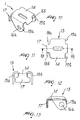
- the reference numeral 1 designates a lever for sports shoes, having a base 2 that is rigidly coupled to a first flap to be joined of the shoe.
- the base 2 is provided with two shoulders 3a, 3b between which a U-shaped lever arm 4 is articulated.
- a traction member 6 is pivoted between the wings 5a, 5b of the lever arm.
- the first ends 7a, 7b of a ring 8 are pivoted to the traction member.
- the ring is therefore open at its first ends 7a, 7b, and there is a second end 9 that lies opposite the first end and is closed.
- the first ends 7a and 7b are curled and are arranged along mutually parallel planes that are approximately perpendicular to the plane of arrangement of the base 2.
- the first and second ends 7a, 7b are tapered, meaning that they are arranged at a distance that is shorter than the width of the second end 9.
- the ring 8 has two arms 10a, 10b, which protrude approximately at right angles to the second end 9 and then have a portion 11a, 11b that is inclined in mutually opposite directions until it blends with the first ends 7a, 7b, which are thus closer to each other and to the longitudinal central axis of the ring 8.
- the first ends 7a, 7b are curled, the curl being obtained by bending the wire that constitutes the ring in a clockwise direction on a plane of arrangement that lies below the one on which the second end 9 and the arms 10a and 10b lie.
- Pivoting between the lever arm 4 and the first ends 7a, 7b is achieved by a suitable pivot 12.
- the ring 8 is made of steel with a diameter of more than 2.3 mm, as generally used in the prior art.
- the ring can be made of steel having a diameter of more than 3 millimeters, preferably approximately 3.5 millimeters.
- This increase in the diameter of the wire not only increases the resistance to deformation of the wire but also gives it a function that can be considered equivalent to a leaf spring, in order to also achieve the possibility to keep the closure load approximately constant even when the flaps, by settling and elongating, tend to reduce the initial closure load of the lever.
- the lever comprises a means for locking the mutual position of the first ends 7a, 7b, which is constituted by a cover 13 that is overmolded at the interspace provided between the first ends 7a, 7b so as to also affect the inclined portions 11 a, 11 b of the ring 8 and partially affect the arms 10a, 10b, the cover being therefore substantially U-shaped.
- the cover 13 therefore has a shape that keeps the first and second ends 7a, 7b at the same distance regardless of the load applied to the ring 8.
- Figures 6 to 13 illustrate a further embodiment, in which the means for locking the mutual position of the first ends 7a, 7b of the ring 8 is constituted by a cover 13 that is preferably made of metal plate and is approximately shaped like an inverted letter U so as to form a dome 14 that is approximately as wide as the distance between the first ends 7a, 7b.
- Wings 15a, 15b protrude from the dome, straddle the first ends 7a, 7b and have, at the curled portion, suitable holes 16a, 16b for the passage of the pivot 12.
- the dome 14 is arc-like, with cavities directed toward the pivot 12.
- the stem 17 of a T-shaped plate protrudes from the dome 14 on the opposite side with respect to the lever arm 4.
- the tabs 18a, 18b of the plate are bent towards the pivot 12 and interact by abutment with the inclined portions 11a, 11b of the ring 8.
- the lever allows to keep the closure load approximately constant even when the flaps, by settling and elongating, tend to reduce the initial closure load of the lever, since the ring acts as a leaf spring.
Landscapes
- Engineering & Computer Science (AREA)
- Mechanical Engineering (AREA)
- Footwear And Its Accessory, Manufacturing Method And Apparatuses (AREA)
Applications Claiming Priority (2)
| Application Number | Priority Date | Filing Date | Title |
|---|---|---|---|
| ITMI20031364 | 2003-07-03 | ||
| IT001364A ITMI20031364A1 (it) | 2003-07-03 | 2003-07-03 | Struttura di leva, particolarmente per calzature sportive. |
Publications (1)
| Publication Number | Publication Date |
|---|---|
| EP1493347A1 true EP1493347A1 (en) | 2005-01-05 |
Family
ID=30131355
Family Applications (1)
| Application Number | Title | Priority Date | Filing Date |
|---|---|---|---|
| EP04014822A Withdrawn EP1493347A1 (en) | 2003-07-03 | 2004-06-24 | Lever particularly for sports shoes |
Country Status (2)
| Country | Link |
|---|---|
| EP (1) | EP1493347A1 (it) |
| IT (1) | ITMI20031364A1 (it) |
Cited By (3)
| Publication number | Priority date | Publication date | Assignee | Title |
|---|---|---|---|---|
| EP1702528A1 (fr) * | 2005-03-15 | 2006-09-20 | Salomon S.A. | Crochet sur-dimensionné |
| FR2896385A1 (fr) * | 2006-01-24 | 2007-07-27 | Salomon Sa | Dispositif de fermeture d'une chaussure de sport |
| EP1985196A1 (fr) | 2007-04-27 | 2008-10-29 | Salomon S.A. | Crochet de fermeture d'une chaussure |
Citations (6)
| Publication number | Priority date | Publication date | Assignee | Title |
|---|---|---|---|---|
| US3258820A (en) * | 1963-04-30 | 1966-07-05 | Steinberg Adalberto Sussman | Pull fastening device for shoes and more particularly for ski shoes |
| US3363288A (en) * | 1966-08-29 | 1968-01-16 | Robert B. Lange | Boot buckle |
| US4051611A (en) * | 1977-01-24 | 1977-10-04 | The Garcia Corporation | Boot buckle |
| US5586367A (en) * | 1994-11-02 | 1996-12-24 | Salomon S.A. | Hook closure for boot |
| FR2755833A1 (fr) * | 1996-11-21 | 1998-05-22 | Salomon Sa | Dispositif de fermeture d'une chaussure comportant des moyens de pre-serrage |
| EP0880912A2 (en) * | 1997-05-29 | 1998-12-02 | Bauer Italia S.p.A. | A method for manufacturing a lever fastening device and a device produced by the method. |
-
2003
- 2003-07-03 IT IT001364A patent/ITMI20031364A1/it unknown
-
2004
- 2004-06-24 EP EP04014822A patent/EP1493347A1/en not_active Withdrawn
Patent Citations (6)
| Publication number | Priority date | Publication date | Assignee | Title |
|---|---|---|---|---|
| US3258820A (en) * | 1963-04-30 | 1966-07-05 | Steinberg Adalberto Sussman | Pull fastening device for shoes and more particularly for ski shoes |
| US3363288A (en) * | 1966-08-29 | 1968-01-16 | Robert B. Lange | Boot buckle |
| US4051611A (en) * | 1977-01-24 | 1977-10-04 | The Garcia Corporation | Boot buckle |
| US5586367A (en) * | 1994-11-02 | 1996-12-24 | Salomon S.A. | Hook closure for boot |
| FR2755833A1 (fr) * | 1996-11-21 | 1998-05-22 | Salomon Sa | Dispositif de fermeture d'une chaussure comportant des moyens de pre-serrage |
| EP0880912A2 (en) * | 1997-05-29 | 1998-12-02 | Bauer Italia S.p.A. | A method for manufacturing a lever fastening device and a device produced by the method. |
Cited By (8)
| Publication number | Priority date | Publication date | Assignee | Title |
|---|---|---|---|---|
| EP1702528A1 (fr) * | 2005-03-15 | 2006-09-20 | Salomon S.A. | Crochet sur-dimensionné |
| FR2883138A1 (fr) * | 2005-03-15 | 2006-09-22 | Salomon Sa | Crochet sur-dimensionne |
| US7603795B2 (en) | 2005-03-15 | 2009-10-20 | Salomon S.A.S. | Buckle for a sports boot and a sports boot having such buckle |
| FR2896385A1 (fr) * | 2006-01-24 | 2007-07-27 | Salomon Sa | Dispositif de fermeture d'une chaussure de sport |
| EP1985196A1 (fr) | 2007-04-27 | 2008-10-29 | Salomon S.A. | Crochet de fermeture d'une chaussure |
| FR2915353A1 (fr) | 2007-04-27 | 2008-10-31 | Salomon Sa | Crochet de fermeture d'une chaussure |
| DE202008016679U1 (de) | 2007-04-27 | 2009-02-26 | Salomon S.A.S. | Schließschnalle eines Schuhs |
| US7987562B2 (en) | 2007-04-27 | 2011-08-02 | Salomon S.A.S. | Buckle for fastening a sports boot and a sports boot having such buckle |
Also Published As
| Publication number | Publication date |
|---|---|
| ITMI20031364A0 (it) | 2003-07-03 |
| ITMI20031364A1 (it) | 2005-01-04 |
Similar Documents
| Publication | Publication Date | Title |
|---|---|---|
| CA1075446A (en) | Boot buckle | |
| CN106256672B (zh) | 保持器 | |
| JPH08224109A (ja) | フック式靴閉鎖具 | |
| US3261244A (en) | Spring attachment for pivotally connected levers | |
| RU2744287C1 (ru) | Рукоятка палки и палка с такой рукояткой | |
| US4489466A (en) | Suspender fastener | |
| JPH10155503A (ja) | 歯付きストラップを締めるための装置 | |
| JPS596003A (ja) | 特にスキ−靴用のバツクル・フアスナ | |
| JPH09103307A (ja) | スポーツ靴の締め付け固定装置 | |
| US20140373320A1 (en) | Safety carabiner comprising a double gate | |
| US6019352A (en) | Vice like grip for chains | |
| US7014156B2 (en) | Cam device for climbing | |
| US10864621B2 (en) | Device for bending a split pin | |
| US5509180A (en) | Buckle for ski boot | |
| EP1493347A1 (en) | Lever particularly for sports shoes | |
| US6311370B1 (en) | Skipole handle equipped with a safety strap | |
| US4936603A (en) | Accessory for linking ski tips together | |
| JPH11514561A (ja) | 折り畳みアームを備えた留め金 | |
| US20060219255A1 (en) | Hair grip with a connection working in elongation | |
| US11173381B2 (en) | Front jaw | |
| US10588384B2 (en) | Device for the comfort-adjustment of the length of a bracelet | |
| US7237794B2 (en) | Snowboard binding | |
| US20070028940A1 (en) | Hair clip provided with a podium | |
| US8864775B2 (en) | Applying forceps for a clip | |
| JP2003510191A (ja) | 片手で操作可能な調節式プライヤ |
Legal Events
| Date | Code | Title | Description |
|---|---|---|---|
| PUAI | Public reference made under article 153(3) epc to a published international application that has entered the european phase |
Free format text: ORIGINAL CODE: 0009012 |
|
| AK | Designated contracting states |
Kind code of ref document: A1 Designated state(s): AT BE BG CH CY CZ DE DK EE ES FI FR GB GR HU IE IT LI LU MC NL PL PT RO SE SI SK TR |
|
| AX | Request for extension of the european patent |
Extension state: AL HR LT LV MK |
|
| AKX | Designation fees paid | ||
| REG | Reference to a national code |
Ref country code: DE Ref legal event code: 8566 |
|
| STAA | Information on the status of an ep patent application or granted ep patent |
Free format text: STATUS: THE APPLICATION IS DEEMED TO BE WITHDRAWN |
|
| 18D | Application deemed to be withdrawn |
Effective date: 20050706 |