EP1493379A1 - Abnehmbare Steuervorrichtung für endoskopische Sonde für medizinische Anwendungen - Google Patents
Abnehmbare Steuervorrichtung für endoskopische Sonde für medizinische Anwendungen Download PDFInfo
- Publication number
- EP1493379A1 EP1493379A1 EP04291478A EP04291478A EP1493379A1 EP 1493379 A1 EP1493379 A1 EP 1493379A1 EP 04291478 A EP04291478 A EP 04291478A EP 04291478 A EP04291478 A EP 04291478A EP 1493379 A1 EP1493379 A1 EP 1493379A1
- Authority
- EP
- European Patent Office
- Prior art keywords
- operating device
- suction
- endoscopic probe
- operating
- handle
- Prior art date
- Legal status (The legal status is an assumption and is not a legal conclusion. Google has not performed a legal analysis and makes no representation as to the accuracy of the status listed.)
- Granted
Links
Images

Classifications
-
- A—HUMAN NECESSITIES
- A61—MEDICAL OR VETERINARY SCIENCE; HYGIENE
- A61B—DIAGNOSIS; SURGERY; IDENTIFICATION
- A61B1/00—Instruments for performing medical examinations of the interior of cavities or tubes of the body by visual or photographical inspection, e.g. endoscopes; Illuminating arrangements therefor
- A61B1/012—Instruments for performing medical examinations of the interior of cavities or tubes of the body by visual or photographical inspection, e.g. endoscopes; Illuminating arrangements therefor characterised by internal passages or accessories therefor
Definitions
- the present invention relates to the field of endoscopic flexible endoscopic probes.
- medical vocation of the fibroscope or videoendoscope type with a channel operating system, an instrumentation input and a suction control.
- endoscopy is generally referred to as a visual examination carried out inside an obscure cavity using an "endoscope”, a “fiberscope”, or a "videoendoscope”.
- fibroscope is generally referred to as an endoscopic probe flexible which, introduced into a dark cavity, allows a user on the one hand observe in an eyepiece a target located inside the cavity and other to change the orientation of the distal end of the probe within the cavity.
- a fiberscope integrates by nature an optical device, an illumination device and a mechanical device.
- the mechanical device of a fiberscope consists of an articulated distal crotch, a handful of control and four cables housed inside a flexible cylindrical sheath connecting the control handle to the articulated distal crotch.
- the handle of fibroscope has two devices manually controlled and acting one on the pair of cables operating the orientation of the béquillage in a plane and the other on the pair of cables actuating the orientation of the béquillage in a plane perpendicular to the previous one.
- the optical device of a fiberscope is constituted of an objective housed in the distal face of a tip integral with the end distal to the crutch, an optical image transport system delivered by the distal lens, the transport system consisting of a flexible beam of ordered optical fibers traveling successively in the articulated bick, in the flexible sheath then in the handle and connecting the eyepiece to the distal lens, and an eyepiece with dioptric adjustment integral with the control handle and allowing the user to observe the magnified image of the target in front the distal lens of the fiberscope and transmitted by the optical transport system image.
- the illumination device of a fiberscope consists of a beam unordered optical fibers running successively in the béquillage articulated, in the flexible sheath, in the handle, then in an umbilical cable secured to the control handle.
- the distal end of the fiber bundle housed in the distal face of the integral end of the distal end of the articulated bowing, illuminates the target observed when its proximal end, housed in a lighting tip integrated in the connection device constituting the proximal end of the umbilical cable, is connected to a generator from light.
- the operation of the fiberscope described above requires in these conditions the joint use of a light generator.
- the operation of the videoendoscope described above requires in these conditions the combined use of a video monitor and a light generator, the light generator is often associated in one box with the processor Videoendoscope video.
- the disinfection constraints concern both the elements operating device, integrated in the endoscopic probe that the external removable elements of said device.
- Said removable elements such that suction control valve and sealing cap, must either be of the disposable type, that is, be removable so that they can be cleaned by brushing before being disinfected by immersion in a disinfectant bath or, better, by autoclaving.
- the fixed elements of the device operating room such as the operating canal and the various connecting tubes fixedly integrated in the control handle, they must be able to be easily cleaned with cylindrical brushes before the endoscopic probe is fully immersed in a disinfection bath.
- Medical endoscopic endoscopic probes allowing the implementation of a suction control and an instrumentation input are practice of two types of architecture.
- the first architecture commonly adopted in endoscopic probes flexible means allowing the implementation of a suction control and a instrumentation input relates to probes such as the one shown in 1, whose control handle 1 has two distinct accesses 41 and 45 to the operating channel 9 connected by a tubular 12, 13 integrated in the handle 1.
- the first of these ports 41, disposed at the distal end of the 1 control handle, relates to the instrument input.
- the second access 45, disposed at the proximal portion of the handle 1, is meanwhile equipped a removable external suction unit F, and groups the order 30 and a suction pipe 10 comprising a nozzle of connection to an external suction pump.
- Such an operating device has been described by the Japanese company OLYMPUS in US Patents 5299561 and US 5840015.
- the second of these architectures concerns endoscopic probes, such as the one described in Figure 2, whose control handle has a single and access to the operating channel, this access being equipped with a device operating E1 external, totally or partially removable according to models, and grouping instrument input, suction control and the connection piece to an external suction pump.
- a device of exploitation has been described by the Japanese company OLYMPUS in patents US 4198958, US 4469090 and US 4561428.
- Another operating device of this type has been described by the Japanese company OLYMPUS in US patents 4736732 and US 4794913.
- Such devices have also been implemented in bronchoscopes of the FBS series manufactured by the Japanese company MACHIDA and in the bronchoscopes of the 20 series manufactured by the company Japanese OLYMPUS.
- the present invention aims to provide an operating device removable for flexible endoscopic probe with preferential vocation medical device and having one and only access to the operating canal 9, this operating device to be both easily removable, ergonomic to handle, and meet the disinfection constraints required by users.
- this operating device comprises a connection duct communicating the suction duct with the insertion duct, and whose length is such that when the operating device is fixed on a endoscopic probe handle, the suction control means is positioned near control means of said handle located in proximal position of said handle.
- This operating device is therefore at the same time removable from the handle 1 endoscope for example to be sterilized, and also ergonomic to use because the suction control 30 is sufficiently close to control means of the endoscope to be manipulated with the same hand than these.
- the length of the connecting pipe is of the order of thickness several fingers of one hand.
- connection means of the insertion duct are designed to ensure the removable attachment of the operating device on the handle.
- this operating device includes additional fastening means located at the assembly level suction, designed to cooperate with complementary fastening means provided on the proximal part of the handle.
- the connecting pipe 16 is made of rigid material.
- control means is a removable tap that can adopt at least one opening configuration allowing the passage of fluid between the channel procedure and a suction tube itself connected to the pump suction, and a closure configuration prohibiting the passage of fluid to the suction line.
- the assembly suction pipe comprises a cylindrical part slidably mounted inside the suction duct, and comprising a blind axial channel and a lateral orifice connecting the outside of the cylindrical part to the inside of the axial cylindrical channel one-eyed, the cylindrical piece closing in the closed configuration, the entry of the suction pipe, the lateral orifice being in the open configuration, in look at the inlet of the suction pipe.
- the cylindrical piece is brought back to the closed configuration by elastic return means.
- the suction duct of the suction assembly is selectively connected by the control means to injection tubing for the selective injection of fluids from the injection tubing to the operating canal.
- the insertion means for insertion of instruments The operating room is equipped with a cap for closing the duct insertion.
- this operating device is essentially made of sterilizable material for medical use such as stainless steel.
- this operating device is made in such a way as to be able to be for single use.
- the invention also relates to a fiberscope and a videoendoscope, equipped with operating device defined above.
- FIG. 1 illustrates a control handle 1 of a fiber optic fiberscope medical, of the prior art, having two distinct accesses 41 and 45 to the canal 9 and an external operating device also representative of the state of the art in the matter.
- this fiberscope has a control handle 1 secured to the distal end of a flexible umbilical cable 7 and the end proximal of a flexible sheath 3 serving in particular for housing the canal flexible operative 9 whose proximal end opens into the distal portion 2 of the control handle 1.
- the distal portion 2 of the control handle 1 of the fiberscope illustrated by the FIG. 1 has a first oblique lateral base 40 in which is provided a cylindrical channel 41 whose proximal end 42 of shape taper is the instrumentation input of the fiberscope and whose end distal C is connected to the proximal end of the operative channel 9 by a rigid cylindrical tubing 12 fixedly housed in the distal portion 2 of the control handle.
- the proximal end of the base 40 has a external shoulder 43 allowing the establishment of a sealing cap 20 of flexible plastic material.
- the cap has a circular hole of passage 21 may be obscured by a cylindrical seal 22 secured a sealing cover 23 resiliently connected to the cap.
- the control handle 1 of the fiberscope illustrated in FIG. also a second lateral base 44 in which is formed a channel cylinder 45 whose proximal end constitutes the suction inlet of the fiberscope to which the suction assembly F is connected and whose the distal end is connected to the distal end of the tubing 12 by a rigid cylindrical tubing 13 fixedly housed in the distal portion 2 of the control handle.
- the proximal portion of the base 44 has a external thread 46 for the connection of the suction assembly F of a removable external operating device.
- the operating device thus comprises a suction assembly F having a tube 55 whose distal end has a circular orifice axial 56 and whose proximal portion houses an axial cylindrical channel 57.
- the tube 55 of the suction assembly F is fixedly secured to a tubing rigid lateral suction 10 whose distal end opens into the canal cylindrical 57 also called suction duct.
- the distal end of the tube 55 is secured to an idle ring 59 whose distal portion has a thread internally to fix the operating device on the handle of command 1 by screwing the ring on the outer thread 46 formed around the second base 44.
- the proximal portion of the tube 55 has a thread 58 to attach to said tube, the valve mechanism 30 described below.
- This removable tap mechanism 30 consists of a cylindrical piece 31 slidably housed in the suction duct 57 formed in the proximal portion of the tube 55 of the operating device.
- the distal part of the cylindrical part 31 has a blind axial channel 34 generally cylindrical and a lateral circular orifice 35 opening into the end proximal of the blind canal 34.
- the proximal portion of the cylindrical piece 31 has a proximal end 33 in the form of a push button, an outer circular shoulder 32 and an idle ring 37 whose slice proximal rests on the proximal face of the shoulder 32 and whose portion distal has an internal thread allowing the ring 37 to be screwed onto the external thread 46 formed around the proximal portion of the tube 55 of the operating device.
- Manual action on the proximal end 33 of the tap mechanism coming into place Coincidentally the lateral orifice 35 and the distal end of the suction tube 10, and thus making it possible to connect the suction tube 10 to the channel 45 formed in the base 44.
- FIG. 2 illustrates the structure of a fiber optic fiberglass handle 1 having a single access 48 to the operating canal 9 proximal position and an external E1 operating device representative of the state of the art in the matter.
- this fiberscope has a control handle 1 secured to the distal end of a flexible umbilical cable 7 and the end proximal of a flexible sheath 3 serving in particular for housing the canal flexible operative 9 whose proximal end opens into the distal portion 2 of the control handle 1.
- the control handle 1 of the fiberscope illustrated in FIG. oblique lateral base 47 in which is formed a cylindrical channel 48 whose distal end is connected to the proximal end of the operative channel 9 by a rigid cylindrical tubing 14 housed in the distal portion 2 of the control handle.
- the proximal portion of the base 47 has a external thread 49 for connecting an operating device E1 external.
- the operating device E1 has the shape of a Y whose branch main, located in the extension of the base 47, houses the canal instrumentation and whose oblique lateral branch houses the suction channel.
- the main branch of the operating device E1 consists of a tube 60 in which is formed a cylindrical channel 61 whose proximal end 63 of conical shape constitutes the instrumentation input.
- the proximal end 63 of the tube 60 has an external shoulder 65 allowing the introduction of the sealing cap 20 described above with reference to Figure 1.
- the end distal C of the tube 60 is secured to an idle ring 64 whose distal portion has an internal thread to fix the operating device E1 on the control handle 1 by screwing the ring 64 on the external thread 49 arranged around the base 47.
- the oblique lateral branch of the device operating E1 consists of a tube 66 fixedly secured to the tube 60 and whose distal end houses an axial channel 67 opening into the end 62 of the channel 61 formed in the tube 60.
- the proximal portion of the tube 66 has an external thread 69 for screwing on said tube the ring 37 of the valve mechanism 30 described above with reference to FIG. previously introduced into the cylindrical channel 68 formed in said part proximal.
- the tube 66 is also fixedly secured to a tubing rigid lateral suction 10 whose distal end opens into the canal cylindrical 68.
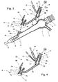
- FIG. 3 illustrates the structure of a medical fiberscope having of a single access 51 to the operating channel 9 and benefiting from the device external procedure which is the subject of the present invention.
- this fiberscope has a control handle 1 secured to the distal end of a flexible umbilical cable 7 and the end proximal of a flexible sheath 3 serving in particular for housing the canal flexible operative 9 whose proximal end opens into the distal portion 2 of the control handle 1.
- the distal portion 2 of the control handle 1 of the fiberscope illustrated by the FIG. 3 has an oblique lateral base 50 in which is arranged a cylindrical axial channel 51 whose distal end is connected to the end proximal to the operating channel 9 by a rigid cylindrical tubing 15 fixedly housed in the distal portion 2 of the control handle.
- the proximal part of the base 50 has an external thread 52 for the connection of the External E2 operating device subject of the present invention.
- the distal portion of the operating device E2 comprises an insertion means A constituted of a cylindrical part 70 in which is formed a conduit inserting instruments 71 whose proximal end 73, of flared shape, constitutes the instrument input.
- the proximal end 73 of the piece cylindrical 70 has an outer shoulder 74 allowing the establishment of the sealing cap 20 described above with reference to FIG. cylindrical 70 is also fixedly secured to a lateral connection duct rigid 16 whose distal end opens into the insertion duct 71.
- the distal end C of the cylindrical piece 70 of the means insertion A is secured to an idle ring 75 whose distal portion has an internal thread for fixing the operating device E2 on the distal portion 2 of the control handle 1 by screwing the idle ring 75 on the external thread 52 formed around the proximal portion of the base 50.
- the proximal part of the operating device E2 consists of a tube 76 whose distal end has a circular orifice 77 in which is the proximal end of the rigid connecting conduit 16.
- proximal tube 76 has an external thread 79 for screwing on said tube the ring 37 of the valve mechanism 30 described above with reference to FIG. 1 and previously introduced into the cylindrical suction duct 78 arranged in the proximal part.
- the tube 76 is also fixedly secured a rigid lateral suction pipe 10 whose distal end opens in the suction duct 78 of cylindrical shape.
- the distal part of the tube 76 has an external lateral finger 80 having a shoulder which, introduced in a slot provided for this purpose on the control handle 1, allows to fix the distal part of the operating device E2 and the handle of order 1.
- Figure 4 illustrates another version of the E3 operating device the object of the present invention, a version making it possible to manage simultaneously with the same valve mechanism the suction and injection functions in the operating channel 9 of a liquid contained in an infusion bag connected by a flexible hose to the operating device E3.
- Implementation in bronchoscopy of such a device makes it possible to perform operations called "alveolar washing".
- the operating device E3 illustrated in FIG. 4 differs from that described with reference to FIG. 3 only by the structure of its proximal portion constituted a tube 76 fixedly secured to a part of a lateral suction pipe 10 whose proximal end opens into the proximal portion of the suction duct 78 in the form of a cylindrical channel formed in the tube 76 and on the other hand a rigid lateral injection tubing 11 whose end proximal opens into the suction duct 78.
- valve mechanism 30 When the valve mechanism 30 is actuated by the user, by sliding in a first open position of the cylindrical part sliding 31, the device allows communication between the tube 10 and the connecting duct 16 and prohibits any communication between the liquid injection tube 11 and the connecting pipe 16.
- valve mechanism 30 When the valve mechanism 30 is actuated by the user, by sliding in a second open position of the cylindrical part sliding 31, the device prohibits communication between the suction tube 10 and the connecting conduit 16 and allows the communication between the tube of liquid injection 11 and the connecting pipe 16.
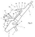
- FIG. 5 illustrates the external appearance of the control handle 1 of a probe video-endoscopy equipped with the operating device E3 described above in reference to Figure 4.
- the distal portion 2 of the control handle has a base 50 housing the access channel of the operating channel and is fixedly secured to the end proximal of the flexible sheath 3 of the videoendoscope, sheath in the end distal of which are integrated various elements (such as articulated bending, illumination window, output of the operating channel, optoelectronic device ...) well known to those skilled in the art and above mentioned.
- the handle of command 1 is secured to the distal end of a cable umbilical 7, cable in the proximal end of which are integrated various elements (such as a connection to a lighting generator, connection to a video processor ...) also well known to specialists in the material and also mentioned above.
- the control handle 1 has a control lever 8 making it possible to order the orientation of the distal bowing of the videoendoscopic probe and a proximal portion 4 equipped with keys 6 for remote control some functions of the video processor connected to the proximal end of the umbilical cable 7.
- the external operating device E3 described above with reference to FIG. is fixed on the control handle 1 by screwing on the base 50 the crazy ring 75 integral with the distal end 70 of the device.
- the proximal portion 82 of the operating device E3 has an input 10, a liquid injection inlet 11, and a mechanism valve 30 fixed on the proximal portion 32 by screwing on the proximal portion of the ring 37 integral with the valve mechanism 30.
- the connecting duct 16 connects the distal end 70 of the operating device E3, distal end equipped with the sealing ring 20 described above in Referring to Figure 1, at the proximal end 82 of the device.
Landscapes
- Health & Medical Sciences (AREA)
- Life Sciences & Earth Sciences (AREA)
- Surgery (AREA)
- Nuclear Medicine, Radiotherapy & Molecular Imaging (AREA)
- Biomedical Technology (AREA)
- Optics & Photonics (AREA)
- Pathology (AREA)
- Radiology & Medical Imaging (AREA)
- Biophysics (AREA)
- Engineering & Computer Science (AREA)
- Physics & Mathematics (AREA)
- Heart & Thoracic Surgery (AREA)
- Medical Informatics (AREA)
- Molecular Biology (AREA)
- Animal Behavior & Ethology (AREA)
- General Health & Medical Sciences (AREA)
- Public Health (AREA)
- Veterinary Medicine (AREA)
- Endoscopes (AREA)
Applications Claiming Priority (2)
| Application Number | Priority Date | Filing Date | Title |
|---|---|---|---|
| FR0308223 | 2003-04-07 | ||
| FR0308223A FR2856912B1 (fr) | 2003-07-04 | 2003-07-04 | Dispositif d'exploitation amovible pour sonde endoscopique souple a vocation medicale |
Publications (2)
| Publication Number | Publication Date |
|---|---|
| EP1493379A1 true EP1493379A1 (de) | 2005-01-05 |
| EP1493379B1 EP1493379B1 (de) | 2007-03-21 |
Family
ID=33427699
Family Applications (1)
| Application Number | Title | Priority Date | Filing Date |
|---|---|---|---|
| EP04291478A Expired - Lifetime EP1493379B1 (de) | 2003-07-04 | 2004-06-11 | Abnehmbare Steuervorrichtung für endoskopische Sonde für medizinische Anwendungen |
Country Status (4)
| Country | Link |
|---|---|
| US (1) | US7220226B2 (de) |
| EP (1) | EP1493379B1 (de) |
| DE (1) | DE602004005379T2 (de) |
| FR (1) | FR2856912B1 (de) |
Cited By (2)
| Publication number | Priority date | Publication date | Assignee | Title |
|---|---|---|---|---|
| FR2955242A1 (fr) * | 2010-01-19 | 2011-07-22 | Axess Vision Technology | Endoscope medical comportant un instrument consommable avec circuit de circulation d'un fluide |
| EP1991288A4 (de) * | 2006-02-24 | 2013-09-18 | Us Endoscopy Group Inc | Endoskopische saugvorrichtung |
Families Citing this family (39)
| Publication number | Priority date | Publication date | Assignee | Title |
|---|---|---|---|---|
| US6989891B2 (en) | 2001-11-08 | 2006-01-24 | Optiscan Biomedical Corporation | Device and method for in vitro determination of analyte concentrations within body fluids |
| US20050267417A1 (en) * | 2004-05-25 | 2005-12-01 | Secrest Dean J | Irrigating biopsy inlet valve |
| USD535393S1 (en) | 2005-03-09 | 2007-01-16 | Karl Storz Gmbh & Co. Kg | Video-bronchoscope |
| JP4716821B2 (ja) * | 2005-08-24 | 2011-07-06 | オリンパスメディカルシステムズ株式会社 | 内視鏡システム、並びに、内視鏡用処置具及び内視鏡 |
| US20070049801A1 (en) * | 2005-08-24 | 2007-03-01 | Lamport Ronald B | Endoscope accessory |
| DE602006006131D1 (de) * | 2005-10-17 | 2009-05-20 | Olympus Medical Systems Corp | Endoskop |
| US20070238928A1 (en) * | 2006-04-07 | 2007-10-11 | Boston Scientific Scimed, Inc. | Biopsy port for easy device passage |
| US7967744B2 (en) * | 2006-04-10 | 2011-06-28 | U.S. Endoscopy Group, Inc. | Biopsy inlet valve |
| US7927271B2 (en) * | 2006-05-17 | 2011-04-19 | C.R. Bard, Inc. | Endoscope tool coupling |
| WO2008144575A2 (en) | 2007-05-18 | 2008-11-27 | Optiscan Biomedical Corporation | Fluid injection and safety system |
| US20120130174A1 (en) * | 2007-08-31 | 2012-05-24 | Simmons Harry W R | Rapid Endoscopic Gastrointestinal Irrigation System for Gastrointestinal Bleeding |
| JP5325416B2 (ja) * | 2007-12-27 | 2013-10-23 | オリンパスメディカルシステムズ株式会社 | 内視鏡本体および内視鏡 |
| US20090208367A1 (en) * | 2008-02-19 | 2009-08-20 | Rosario Sam Calio | Autoclavable bucketless cleaning system |
| US10271716B2 (en) | 2008-06-27 | 2019-04-30 | C.R. Bard, Inc. | Endoscopic vacuum controller |
| DE102008033366A1 (de) * | 2008-07-08 | 2010-01-14 | Aesculap Ag | Medizinische Vorrichtung |
| US20100012152A1 (en) * | 2008-07-21 | 2010-01-21 | Hansen Adam J | Systems and methods for trocar cleaning |
| GB2463067B (en) * | 2008-09-01 | 2010-08-04 | Keymed | Adaptor for an endoscope |
| US20100121141A1 (en) * | 2008-11-12 | 2010-05-13 | Michael Rontal | Endoscopic cutting and debriding device mounted on a flexible and maneuverable tube employing a fluid-driven turbine |
| US20110144573A1 (en) * | 2009-09-30 | 2011-06-16 | Broadcom Corporation | Bio-medical unit system for medication control |
| SE534409C2 (sv) * | 2009-10-01 | 2011-08-09 | Westinghouse Electric Sweden | Apparat och metod för rengöring av ett nukleärt bränsleelement |
| EP2549931B1 (de) | 2010-03-24 | 2019-12-04 | United States Endoscopy Group, Inc. | Mehrfachbiopsievorrichtung |
| US20110245603A1 (en) * | 2010-03-30 | 2011-10-06 | Brannon James K | Laser endoscopic surgical instrument |
| US8702596B2 (en) | 2010-09-17 | 2014-04-22 | United States Endoscopy Group, Inc. | Biopsy inlet valve improvements |
| EP2498196A2 (de) * | 2011-02-17 | 2012-09-12 | Broadcom Corporation | Biomedizinisches Einheitensystem zur Medikamentenverabreichungssteuerung |
| USD687476S1 (en) * | 2011-04-27 | 2013-08-06 | Karl Storz Imaging, Inc. | Video camera |
| US9744276B2 (en) * | 2012-03-20 | 2017-08-29 | Prabhat Kumar Ahluwalia | Suction device |
| CN103908213A (zh) * | 2012-12-29 | 2014-07-09 | 上海澳华光电内窥镜有限公司 | 一种脱卸式内视镜装置 |
| RU2526948C1 (ru) * | 2013-06-19 | 2014-08-27 | Общество С Ограниченной Ответственностью "Айсберг" | Видеоэндоскоп и комплект видеоэндоскопов |
| CN103584827B (zh) * | 2013-11-27 | 2016-09-07 | 中国科学院深圳先进技术研究院 | 医用内窥镜一次性护套及医用内窥镜 |
| US11419656B2 (en) * | 2014-04-04 | 2022-08-23 | Cpsi Holdings Llc | Thermal regulation catheter system |
| US11246566B2 (en) * | 2015-06-26 | 2022-02-15 | B-K Medical Aps | US imaging probe with an instrument channel |
| WO2017024068A2 (en) * | 2015-08-04 | 2017-02-09 | Alphinity, Llc | Fluid plug for sterile processes and methods of using the same |
| US10856729B2 (en) | 2016-02-29 | 2020-12-08 | Covidien Lp | Surgical system having a guide catheter including a fluid passageway |
| US10973396B2 (en) * | 2017-01-30 | 2021-04-13 | Covidien Lp | Enhanced ablation and visualization techniques |
| USD947376S1 (en) | 2018-03-21 | 2022-03-29 | Medivators Inc. | Endoscope suction valve |
| JP7411562B2 (ja) | 2018-03-21 | 2024-01-11 | メディヴェーターズ インコーポレイテッド | 内視鏡用の使い捨て可能な弁 |
| USD952142S1 (en) | 2018-05-21 | 2022-05-17 | Medivators Inc. | Cleaning adapter |
| WO2019226307A1 (en) | 2018-05-21 | 2019-11-28 | Medivators Inc. | Cleaning adapter with and without safety tag |
| DE102020109966A1 (de) * | 2020-04-09 | 2021-10-14 | Hoya Corporation | Endoskop mit Arbeitskanal und Steuerkörper |
Citations (3)
| Publication number | Priority date | Publication date | Assignee | Title |
|---|---|---|---|---|
| US3830225A (en) * | 1973-01-31 | 1974-08-20 | J Shinnick | Multiple purpose stopcock arrangement for suctioning, injection, oxygen cessory equipment |
| WO1993025139A1 (en) * | 1992-06-18 | 1993-12-23 | Nikomed Aps | An instrument and an assembly for surgical use |
| DE19721030C1 (de) * | 1997-05-20 | 1998-12-17 | Karlsruhe Forschzent | Vorrichtung zum Führen einer medizinischen Sonde |
Family Cites Families (52)
| Publication number | Priority date | Publication date | Assignee | Title |
|---|---|---|---|---|
| US4198958A (en) * | 1977-06-01 | 1980-04-22 | Olympus Optical Co., Ltd. | Flexible cap and instrument seal for a suction control device in an endoscope |
| US4361138A (en) * | 1980-03-31 | 1982-11-30 | Olympus Optical Company Ltd. | Ventilation/feedwater switching apparatus for endoscope |
| US4469090A (en) * | 1980-12-19 | 1984-09-04 | Olympus Optical Co., Ltd. | Suction control device for an endoscope |
| JPS6023001U (ja) * | 1983-07-18 | 1985-02-16 | オリンパス光学工業株式会社 | 内視鏡の吸引制御装置 |
| US4661110A (en) * | 1985-05-13 | 1987-04-28 | Sherwood Medical Company | Multiple passage connector fitting for a medical tube |
| US4736732A (en) * | 1985-09-03 | 1988-04-12 | Olympus Optical Co., Ltd. | Endoscopic fluid changing device |
| SE453801B (sv) * | 1986-08-06 | 1988-03-07 | Ingvar Andersson | Koppling for medicinskt bruk |
| JPS63143025A (ja) * | 1986-12-04 | 1988-06-15 | オリンパス光学工業株式会社 | 内視鏡の吸引制御装置 |
| JPH065761Y2 (ja) * | 1988-04-25 | 1994-02-16 | 旭光学工業株式会社 | 内視鏡 |
| US4994048A (en) * | 1988-09-19 | 1991-02-19 | Becton, Dickinson And Company | Apparatus and method for connecting a passageway and openings with a connector |
| US5257773A (en) * | 1991-01-25 | 1993-11-02 | Olympus Optical Co., Ltd. | Endoscope suction operating apparatus |
| US5209219A (en) * | 1991-03-18 | 1993-05-11 | Laser Medical Research Foundation | Endoscope adaptor |
| JPH0549596A (ja) * | 1991-08-21 | 1993-03-02 | Olympus Optical Co Ltd | 内視鏡の吸引制御装置 |
| US5354291A (en) * | 1992-10-09 | 1994-10-11 | Symbiosis Corporation | Probe for endoscopic suction-irrigation instruments having a proximal port for receiving an additional probe therethrough |
| US5350356A (en) * | 1992-10-09 | 1994-09-27 | Symbiosis Corporation | Endoscopic suction-irrigation instrument with insertable probe lockable in partially withdraw position |
| US5569222A (en) * | 1994-06-21 | 1996-10-29 | Clintec Nutrition Company | Adapter for a variety of tubes having various diameters and a method of using the adapter |
| JP3380080B2 (ja) * | 1995-03-17 | 2003-02-24 | ペンタックス株式会社 | 内視鏡の吸引管路切換装置 |
| US5860953A (en) * | 1995-11-21 | 1999-01-19 | Catheter Imaging Systems, Inc. | Steerable catheter having disposable module and sterilizable handle and method of connecting same |
| US6004263A (en) * | 1996-03-13 | 1999-12-21 | Hihon Kohden Corporation | Endoscope with detachable operation unit and insertion unit |
| US5848997A (en) * | 1996-03-15 | 1998-12-15 | Becton Dickinson And Company | Disconnect for medical access devices |
| DE19715510C2 (de) * | 1997-04-14 | 2000-05-18 | Storz Karl Gmbh & Co Kg | Endoskop mit einem Kameramodul und einer Kupplung |
| DE19715507C1 (de) * | 1997-04-14 | 1999-02-04 | Storz Karl Gmbh & Co | Medizinisches Instrument mit einem tubusartigen Element und einem dazu abgewinkelten Griff, insbesondere Mediastinoskop, Laryngoskop, Divertikuloskop |
| US5910105A (en) * | 1997-04-14 | 1999-06-08 | C.R. Bard, Inc. | Control handle for an endoscope |
| ATE260606T1 (de) * | 1997-06-02 | 2004-03-15 | Cook Urological Inc | Austauschbares handstück für eine medizinische vorrichtung |
| US5992899A (en) * | 1997-09-17 | 1999-11-30 | Becton, Dickinson And Company | Adapter for mounting a fluid handling device on a catheter tubing |
| US5989240A (en) * | 1998-02-27 | 1999-11-23 | Becton, Dickson And Company | Adaptor for mounting a fluid handling device on a catheter tubing |
| DE19906191A1 (de) * | 1999-02-15 | 2000-08-17 | Ingo F Herrmann | Endoskop |
| US6254061B1 (en) * | 1999-04-30 | 2001-07-03 | Scimed Life Systems, Inc. | Medical suction valve |
| US6890298B2 (en) * | 1999-10-14 | 2005-05-10 | Karl Storz Gmbh & Co. Kg | Video laryngoscope with detachable light and image guides |
| US6808521B1 (en) * | 1999-11-18 | 2004-10-26 | Kimberly-Clark Worldwide, Inc. | Enteral feeding adapter |
| US6423053B1 (en) * | 2000-01-12 | 2002-07-23 | Han-Pin Lee | Releasable tube assembly |
| US6406470B1 (en) * | 2000-02-22 | 2002-06-18 | Atc Technologies, Inc. | Surgical probe and value assembly and threaded quick disconnect adapter for use therewith |
| US6652509B1 (en) * | 2000-04-03 | 2003-11-25 | Abbott Laboratories | Housing capable of connecting a container to a medical device |
| JP2003533257A (ja) * | 2000-05-15 | 2003-11-11 | シー・アール・バード・インク | 内視鏡用アクセサリー装着メカニズム |
| US6652488B1 (en) * | 2000-09-11 | 2003-11-25 | Stryker Corporation | Surgical suction irrigator |
| JP4538680B2 (ja) * | 2000-09-29 | 2010-09-08 | 富士フイルム株式会社 | 内視鏡の管路接続構造 |
| US6860516B2 (en) * | 2001-12-07 | 2005-03-01 | Pentax Corporation | Channel tube coupling structure for anti-pollution type endoscope |
| DE10216928B4 (de) * | 2002-04-17 | 2004-07-15 | Olympus Winter & Ibe Gmbh | In ein Endoskop einsetzbares Einweginstrument |
| JP4657718B2 (ja) * | 2002-09-06 | 2011-03-23 | シー・アール・バード・インク | 内視鏡の外部にある内視鏡付属品制御システム |
| JP4667038B2 (ja) * | 2002-09-06 | 2011-04-06 | シー・アール・バード・インク | 内視鏡付属品装着アダプタ |
| JP4200731B2 (ja) * | 2002-10-23 | 2008-12-24 | フジノン株式会社 | 内視鏡の鉗子栓 |
| US7758497B2 (en) * | 2003-06-20 | 2010-07-20 | Contura A/S | Endoscopic attachment device |
| JP4144444B2 (ja) * | 2003-06-20 | 2008-09-03 | フジノン株式会社 | 内視鏡の送液装置 |
| US20050245899A1 (en) * | 2003-10-28 | 2005-11-03 | Swisher David R | Dual purpose adapter |
| JP4594612B2 (ja) * | 2003-11-27 | 2010-12-08 | オリンパス株式会社 | 挿入補助具 |
| JP4451124B2 (ja) * | 2003-11-28 | 2010-04-14 | オリンパス株式会社 | 内視鏡用処置具挿抜システム |
| JP3864344B2 (ja) * | 2003-12-05 | 2006-12-27 | フジノン株式会社 | 内視鏡の挿入補助具 |
| CN100453025C (zh) * | 2004-02-16 | 2009-01-21 | 奥林巴斯株式会社 | 内窥镜系统 |
| US20050203543A1 (en) * | 2004-03-15 | 2005-09-15 | Nabil Hilal | Surgical guide valve |
| US20050222494A1 (en) * | 2004-04-06 | 2005-10-06 | Prescott James T | Dual-scope colonoscopy system with separate secondary colonoscope tool |
| US20060041189A1 (en) * | 2004-08-17 | 2006-02-23 | Vancaillie Thierry G | Grummet |
| US20060135846A1 (en) * | 2004-12-17 | 2006-06-22 | Hunt John V | Endoscopic device and component attachable to an endoscope handpiece |
-
2003
- 2003-07-04 FR FR0308223A patent/FR2856912B1/fr not_active Expired - Lifetime
-
2004
- 2004-06-11 DE DE602004005379T patent/DE602004005379T2/de not_active Expired - Lifetime
- 2004-06-11 EP EP04291478A patent/EP1493379B1/de not_active Expired - Lifetime
- 2004-06-29 US US10/880,186 patent/US7220226B2/en not_active Expired - Lifetime
Patent Citations (3)
| Publication number | Priority date | Publication date | Assignee | Title |
|---|---|---|---|---|
| US3830225A (en) * | 1973-01-31 | 1974-08-20 | J Shinnick | Multiple purpose stopcock arrangement for suctioning, injection, oxygen cessory equipment |
| WO1993025139A1 (en) * | 1992-06-18 | 1993-12-23 | Nikomed Aps | An instrument and an assembly for surgical use |
| DE19721030C1 (de) * | 1997-05-20 | 1998-12-17 | Karlsruhe Forschzent | Vorrichtung zum Führen einer medizinischen Sonde |
Cited By (4)
| Publication number | Priority date | Publication date | Assignee | Title |
|---|---|---|---|---|
| EP1991288A4 (de) * | 2006-02-24 | 2013-09-18 | Us Endoscopy Group Inc | Endoskopische saugvorrichtung |
| FR2955242A1 (fr) * | 2010-01-19 | 2011-07-22 | Axess Vision Technology | Endoscope medical comportant un instrument consommable avec circuit de circulation d'un fluide |
| WO2011089349A1 (fr) * | 2010-01-19 | 2011-07-28 | Axess Vision Technology | Endoscope medical comportant un instrument consommable avec circuit de circulation d'un fluide |
| US8876705B2 (en) | 2010-01-19 | 2014-11-04 | Axess Vision Technology | Medical endoscope comprising a consumable instrument having a fluid flow circuit |
Also Published As
| Publication number | Publication date |
|---|---|
| DE602004005379D1 (de) | 2007-05-03 |
| EP1493379B1 (de) | 2007-03-21 |
| FR2856912A1 (fr) | 2005-01-07 |
| FR2856912B1 (fr) | 2008-05-23 |
| US7220226B2 (en) | 2007-05-22 |
| DE602004005379T2 (de) | 2007-12-13 |
| US20050027165A1 (en) | 2005-02-03 |
Similar Documents
| Publication | Publication Date | Title |
|---|---|---|
| EP1493379B1 (de) | Abnehmbare Steuervorrichtung für endoskopische Sonde für medizinische Anwendungen | |
| AU2006245250B2 (en) | Distal end portion of endoscope | |
| EP1524543B1 (de) | Endoskop mit ultravioletter Bestrahlung | |
| CA2648069C (fr) | Protection pour endoscope et endoscope correspondant | |
| EP4063837B1 (de) | Vorrichtung zur endoskopischen fehlersuche an bauteilen | |
| JP5030507B2 (ja) | 内視鏡の先端フードとフード付き内視鏡 | |
| CN100586360C (zh) | 内窥镜用插入部 | |
| US10709313B2 (en) | Surgical instrument inspection system | |
| WO2013128136A2 (fr) | Dispositif de micro-endoscopie de precision et micro-endoscope associe | |
| US20130035553A1 (en) | Endoscope with multiple working channel ports | |
| EP2344018A2 (de) | Instrument für ein endoskop | |
| JP3577264B2 (ja) | 耳道内視掃除装置 | |
| JP2012045328A (ja) | 内視鏡及び外套管並びに内視鏡システム | |
| WO2015151968A1 (ja) | 超音波内視鏡 | |
| TR201816576T4 (tr) | Rijit kavisli bir şaft içeren endoskop ve bu tür bir endoskopun üretilmesi için usul. | |
| FR3032808A1 (de) | ||
| FR2945723A1 (fr) | Instrument medical a fonctions multiples pour endoscope. | |
| FR3109289A1 (fr) | Système d’endoscopie et accessoire pour colonne d’endoscopie | |
| WO2010146298A2 (fr) | Endoscope comprenant un module à usage unique | |
| FR3106267A1 (fr) | Endoscope pourvu d’un dispositif d’obturation d’un circuit de circulation d’un fluide, pour une stérilisation améliorée | |
| JP3228718B2 (ja) | 内視鏡 | |
| JP3181659B2 (ja) | 内視鏡 | |
| FR2803755A1 (fr) | Dispositif de nettoyage et desinfection pour endoscope medicaux | |
| JP2000237126A (ja) | 内視鏡の管路構造 | |
| JP6671967B2 (ja) | 内視鏡 |
Legal Events
| Date | Code | Title | Description |
|---|---|---|---|
| PUAI | Public reference made under article 153(3) epc to a published international application that has entered the european phase |
Free format text: ORIGINAL CODE: 0009012 |
|
| AK | Designated contracting states |
Kind code of ref document: A1 Designated state(s): AT BE BG CH CY CZ DE DK EE ES FI FR GB GR HU IE IT LI LU MC NL PL PT RO SE SI SK TR |
|
| AX | Request for extension of the european patent |
Extension state: AL HR LT LV MK |
|
| 17P | Request for examination filed |
Effective date: 20050128 |
|
| 17Q | First examination report despatched |
Effective date: 20050224 |
|
| AKX | Designation fees paid |
Designated state(s): DE |
|
| GRAP | Despatch of communication of intention to grant a patent |
Free format text: ORIGINAL CODE: EPIDOSNIGR1 |
|
| GRAS | Grant fee paid |
Free format text: ORIGINAL CODE: EPIDOSNIGR3 |
|
| GRAA | (expected) grant |
Free format text: ORIGINAL CODE: 0009210 |
|
| AK | Designated contracting states |
Kind code of ref document: B1 Designated state(s): DE |
|
| REF | Corresponds to: |
Ref document number: 602004005379 Country of ref document: DE Date of ref document: 20070503 Kind code of ref document: P |
|
| PLBE | No opposition filed within time limit |
Free format text: ORIGINAL CODE: 0009261 |
|
| STAA | Information on the status of an ep patent application or granted ep patent |
Free format text: STATUS: NO OPPOSITION FILED WITHIN TIME LIMIT |
|
| 26N | No opposition filed |
Effective date: 20071227 |
|
| PGFP | Annual fee paid to national office [announced via postgrant information from national office to epo] |
Ref country code: DE Payment date: 20230523 Year of fee payment: 20 |
|
| REG | Reference to a national code |
Ref country code: DE Ref legal event code: R071 Ref document number: 602004005379 Country of ref document: DE |