EP1493463A1 - Fil d' electrode - Google Patents
Fil d' electrode Download PDFInfo
- Publication number
- EP1493463A1 EP1493463A1 EP04090230A EP04090230A EP1493463A1 EP 1493463 A1 EP1493463 A1 EP 1493463A1 EP 04090230 A EP04090230 A EP 04090230A EP 04090230 A EP04090230 A EP 04090230A EP 1493463 A1 EP1493463 A1 EP 1493463A1
- Authority
- EP
- European Patent Office
- Prior art keywords
- electrode line
- electrode
- bristles
- micro
- microstructure
- Prior art date
- Legal status (The legal status is an assumption and is not a legal conclusion. Google has not performed a legal analysis and makes no representation as to the accuracy of the status listed.)
- Granted
Links
- 238000006073 displacement reaction Methods 0.000 claims description 14
- 210000003128 head Anatomy 0.000 description 6
- BASFCYQUMIYNBI-UHFFFAOYSA-N platinum Chemical compound [Pt] BASFCYQUMIYNBI-UHFFFAOYSA-N 0.000 description 4
- 230000002861 ventricular Effects 0.000 description 4
- 230000001746 atrial effect Effects 0.000 description 2
- -1 ethylene chlorotrifluoroethylene, ethylene tetrafluoroethylene Chemical group 0.000 description 2
- PCHJSUWPFVWCPO-UHFFFAOYSA-N gold Chemical compound [Au] PCHJSUWPFVWCPO-UHFFFAOYSA-N 0.000 description 2
- 239000010931 gold Substances 0.000 description 2
- 229910052737 gold Inorganic materials 0.000 description 2
- 239000000463 material Substances 0.000 description 2
- 210000004165 myocardium Anatomy 0.000 description 2
- 229910052697 platinum Inorganic materials 0.000 description 2
- 229940058401 polytetrafluoroethylene Drugs 0.000 description 2
- 239000004810 polytetrafluoroethylene Substances 0.000 description 2
- 239000000758 substrate Substances 0.000 description 2
- 208000001840 Dandruff Diseases 0.000 description 1
- 239000004642 Polyimide Substances 0.000 description 1
- 239000004743 Polypropylene Substances 0.000 description 1
- 206010000496 acne Diseases 0.000 description 1
- 230000001154 acute effect Effects 0.000 description 1
- 238000004873 anchoring Methods 0.000 description 1
- 230000009286 beneficial effect Effects 0.000 description 1
- 230000015572 biosynthetic process Effects 0.000 description 1
- 210000005242 cardiac chamber Anatomy 0.000 description 1
- 230000008021 deposition Effects 0.000 description 1
- 229920000840 ethylene tetrafluoroethylene copolymer Polymers 0.000 description 1
- 238000005755 formation reaction Methods 0.000 description 1
- 238000002513 implantation Methods 0.000 description 1
- 238000002347 injection Methods 0.000 description 1
- 239000007924 injection Substances 0.000 description 1
- 238000001746 injection moulding Methods 0.000 description 1
- 238000003780 insertion Methods 0.000 description 1
- 230000037431 insertion Effects 0.000 description 1
- 238000000034 method Methods 0.000 description 1
- 229920001721 polyimide Polymers 0.000 description 1
- 229920001155 polypropylene Polymers 0.000 description 1
- 229920001296 polysiloxane Polymers 0.000 description 1
- 229920002635 polyurethane Polymers 0.000 description 1
- 239000004814 polyurethane Substances 0.000 description 1
- 239000000565 sealant Substances 0.000 description 1
- 239000004590 silicone sealant Substances 0.000 description 1
- 239000000243 solution Substances 0.000 description 1
- 239000010409 thin film Substances 0.000 description 1
- 210000001585 trabecular meshwork Anatomy 0.000 description 1
Images




Classifications
-
- A—HUMAN NECESSITIES
- A61—MEDICAL OR VETERINARY SCIENCE; HYGIENE
- A61N—ELECTROTHERAPY; MAGNETOTHERAPY; RADIATION THERAPY; ULTRASOUND THERAPY
- A61N1/00—Electrotherapy; Circuits therefor
- A61N1/02—Details
- A61N1/04—Electrodes
- A61N1/05—Electrodes for implantation or insertion into the body, e.g. heart electrode
- A61N1/056—Transvascular endocardial electrode systems
-
- A—HUMAN NECESSITIES
- A61—MEDICAL OR VETERINARY SCIENCE; HYGIENE
- A61N—ELECTROTHERAPY; MAGNETOTHERAPY; RADIATION THERAPY; ULTRASOUND THERAPY
- A61N1/00—Electrotherapy; Circuits therefor
- A61N1/02—Details
- A61N1/04—Electrodes
- A61N1/05—Electrodes for implantation or insertion into the body, e.g. heart electrode
- A61N1/056—Transvascular endocardial electrode systems
- A61N1/057—Anchoring means; Means for fixing the head inside the heart
Definitions
- the invention relates to an implantable electrode lead with a proximal and a distal end, an outer electrode line surface and a Electrode line longitudinal axis.
- Electrodes for example for pacemakers
- Previous solutions for the fixation of electrode line in the heart and in vessels are for example preformed electrode lines, which clamp the electrode in vessels.
- the distal End of the electrode lead attached to the electrode screws or spirals which are designed to screw the electrode to a myocardium to fix.
- Hooks are known from the prior art, which at the distal end or are mounted on the electrode line and are formed, the electrode line to fixate on the myocardium.
- Applicant's patent application WO 97/31678 describes an electrode arrangement with a ventricular electrode, which hook-shaped fastening means on having distal end of the electrode.
- the electrode line is designed to be flexible between the atrial electrode and the ventricular electrode to form a loop.
- This electrode line has in the Near the atrial electrodes, a first passive fastening device in the form of hooks, as well as near the ventricular electrodes at the distal end of one Fastening device with two hooks on.
- the invention is based Task is to provide an implantable electrode lead, which is a safe Fixation of the electrode line in the heart and in vessels allows.
- an electrode lead of the invention mentioned type which in the region of the distal end at least one for provided lateral contact a vessel wall, in a multiple electrode line diameter arranged measuring distance to the distal end, Surface area having a microstructure.
- the microstructure is through a Variety of arranged on the electrode line surface, over the surface area distributed both in the longitudinal direction and in the circumferential direction, itself with a radial direction component, preferably outwardly extending Microstructure elements formed.
- the microstructure elements have a radial Expansion, which is a fraction of the electrode line diameter and are formed, upon touching a vessel wall, a displacement of the electrode lead counteract along the electrode line longitudinal axis.
- an electrode line is that many microstructure elements, which measure a fraction of the electrode line diameter and distributed to a surface area of the electrode line, a larger one Liability is achieved as for example in an electrode line, which only has one or more hooks on the surface to the electrode lead to fix.
- the microstructure elements are microbristles formed, wherein the micro-bristles at a predetermined angle to Electrode line surface are arranged.
- the angle can be 90 °, for example be. This causes advantageous that the electrode line against a longitudinal axis Displacement both in the direction of the proximal end and in the direction of the the distal end is equally secured.
- the micro bristles are arranged parallel to the electrode line longitudinal axis, particularly preferred are the micro bristles with a directional component oriented facing the proximal end of the electrode lead.
- a microstructured surface area have both microstructure elements, which with a directional component pointing to the proximal end, as well as those microstructural elements, which with aligned with a directional component facing the distal end of the electrode lead are.
- the micro bristles are preferably along the electrode line longitudinal axis alternating with a proximal and a distal directional component aligned. This advantageously causes a fixation of the electrode line at a displacement along the electrode line longitudinal axis both in the direction to the proximal, as well as toward the distal end of the electrode line.
- the micro bristles are in a predetermined Angle to the electrode line surface arranged and in a predetermined Angle to the longitudinal axis of the electrode line in each case aligned parallel to each other.
- the micro bristles in this embodiment with a Directional component aligned facing the proximal end of the electrode lead. This advantageously causes the electrode line to rotate around the longitudinal axis in the circumferential direction can be screwed into a vessel.
- the bristles are formed flat when screwed to the electrode surface to apply. A rotation opposite to the screw causes a Fixation of the electrode lead, a repeated rotation in screw-in direction, a loosening of the electrode line.
- the microstructure elements are formed as nubs, which are formed are to adhere by adhesion to a vessel wall.
- This is indicated by the nubs preferably has a flat adhesion surface which is perpendicular to the radial direction the electrode line is arranged. In contact with appropriate pressure to a vessel wall, a sufficiently thin film of moisture between form the adhesion surface and the vessel wall. As a result, adhesion forces generated, which fix the electrode lead to the vessel wall.
- knobs are designed as suction cups. These can be the Nubs instead of the flat adhesion surface a concave shaped adhesion surface exhibit.
- the microstructure elements are as scales with a Scaled edge formed.
- the flakes are in a predetermined Angle, more preferably acute angle to the electrode line surface such arranged that the scale edge of the electrode line surface is spaced. More preferably, the flakes are arranged such that at least an edge portion of the flake edge a perpendicular to the electrode line longitudinal axis having extending alignment component. That causes advantageous that the electrode line is in contact with a vessel wall along the Electrode line longitudinal axis is easily displaceable in one direction and in the opposite direction by intervention of the scales edges in the vessel wall given an increased resistance to a longitudinal axial displacement is.
- the flakes at the scaly edge at least one point. This jag can be beneficial in addition to the Scaly edge into the vessel wall and thus a further increased resistance form against a longitudinal axial displacement.
- the microstructure elements can be applied to the electrode line surface or be formed from this.
- the microstructure is in a micro-stereolithographic Process prepared, for example by deposition on a Substrate.
- the substrate may be deposited on the electrode line surface be or be formed by the electrode line surface itself.
- a surface area with a microstructure may also be microstereolithographically produced produced form.
- An electrode lead may have one or more surface areas with a microstructure having one embodiment or a combination of different Embodiments of microstructure elements such as micro bristles, Shed, nubs or the embodiments shown in the figures of microstructure elements realized on exactly one electrode line can be.
- Suitable materials for the electrode line are, for example, poly-tetra-fluoro-ethylene (PTFE), silicones, polyimide, ethylene chlorotrifluoroethylene, ethylene tetrafluoroethylene (ETFE), polypropylene or polyurethanes.
- PTFE poly-tetra-fluoro-ethylene
- silicones silicones
- polyimide polyimide
- ethylene chlorotrifluoroethylene ethylene chlorotrifluoroethylene
- ETFE ethylene tetrafluoroethylene
- polypropylene or polyurethanes polyurethanes.
- the microstructures can together with the electrode line or a portion of the electrode line be produced by injection molding, wherein the microstructures in one Injection mold can be incorporated accordingly.
- an electrode lead For easy insertion of the electrode lead into a lumen, an electrode lead have a longitudinally axially displaceable shell, which is located on the electrode line arrange so as to obscure the microstructure and in the application by retracting in the proximal direction to release the microstructure.
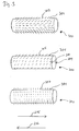
- FIG. 1 shows-schematically illustrated-the distal end of an electrode lead 100 with an electrode line surface 101 and surface areas 105 and 106, each having a microstructure.
- the surface area 105 is in Distance 104 from an electrode located at the distal end of the electrode lead 103 arranged.
- the surface area 105 with a microstructure occupies Circumferential direction only a part of the electrode line surface.
- a circumferential surface area 106 which is in full Circumferentially covers the outer electrode line surface 101.
- the surface area 106 in this example is at a distance 102 from that at the distal end located electrode 103 is arranged.
- two of the embodiments are of surface areas - circumferential and non-circumferential - common shown on an electrode line.
- An electrode line in the sense of Invention may be at least one circumferential in the circumferential direction of the electrode line Surface area 106 or at least one non-circumferential surface area 105 have.
- an electrode line in the sense the invention several circumferential in the circumferential direction of the electrode line surface areas 106 or more non-circumferential surface areas 105 have.
- a combination of circumferential surface areas 106 and result in non-circumferential surface areas 105 on an electrode line various, not shown here variant embodiments.
- the distances 102 and 104 may both be multiple electrode line diameters 110 and are shown schematically in this example.
- the surface areas 106 and 105 have a microstructure, wherein the microstructure through a variety of the electrode line surface arranged over the surface area both longitudinally and circumferentially distributed microstructure elements is formed.
- Various embodiments of microstructure elements will be shown below in Figure 2.
- FIG. 2 shows a schematic representation of various embodiments of Microstructural features. These microstructure elements have a radial extent beyond the electrode line surface, which is a fraction of the electrode line diameter is. The microstructure elements are formed when touching a vessel wall, a displacement of the electrode line in the longitudinal direction counteract.
- microstructure elements 203 attached, which are formed as curved micro-bristles.
- the microbristles 203 are with a pointing in the proximal direction 215 direction component curved.
- the micro-bristles 203 thereby generate upon displacement of the Electrode lead in the proximal direction 215 an increased resistance to a displacement of the electrode line in the distal direction 216.
- the micro-bristles may also be formed as rectilinear micro-bristles 205. These rectilinear micro-bristles 205 are at a predetermined angle to the electrode line surface 201 arranged so that it is an alignment component in the proximal direction 215.
- the micro-bristles 207 are also rectilinear and are perpendicular to the electrode line surface 201 arranged. This will be at a shift the electrode line in the proximal direction 215 and in the distal direction 216 produces an equally high resistance.
- the micro-bristles 209 are mounted on the electrode line surface 201 and have at the electrode line surface 201 facing away from an in Proximal direction 215 molded hook 210 on.
- This hook 210 is formed with a displacement of the electrode line in the proximal direction 215 in FIG to intervene a vessel wall and thereby a particularly high resistance to to produce a displacement of the electrode line in the proximal direction 215.
- the micro-bristles 211 are also like the micro-bristles 203 in the proximal direction 215 curved and facing away from the electrode line surface 201 End of a star-shaped branch 212 on. Through this education can the micro-bristles 211 in contact with a vessel wall particularly effective in this Engage and thus create a high resistance to displacement the electrode lead in the proximal direction 215.
- FIG. 3 schematically shows an arrangement example of micro-bristles an electrode line. Shown are sections of an electrode line 300, on whose electrode line surface 301 are mounted micro bristles. The microbristles 303 are at a predetermined angle to the electrode line surface 301 aligned with a directional component in the proximal direction 215.
- micro-bristles 305 are at a predetermined angle to the electrode line surface 301 and arranged with a directional component aligned in the proximal direction 215.
- the micro-bristles 305 are also in a predetermined angle to the electrode line longitudinal axis in each case parallel to each other aligned so that upon rotation of the electrode line in the circumferential direction 309, the micro-bristles 305 in contact with a vessel wall in anchor it.
- the micro-bristles 305 may be from the Loosen the vessel wall anchoring again.
- the micro-bristles 307 are arranged orthogonally on the electrode line surface 301. As a result, both in displacement of the electrode line in proximal Direction 215 and when moving the electrode line in the distal direction 216 an equally high resistance to the displacement movement set.
- FIG. 4 schematically shows sections of an electrode line 400 various embodiments of microstructure elements, which as scales are formed. The embodiments shown in this figure are partial shown together on an electrode line section. An electrode line can each one of the embodiments shown or a combination have various embodiments.
- the flakes 403 are at a predetermined angle to the electrode line surface 401 aligned in the proximal direction 215.
- the scales 403 have a perpendicular to the electrode line longitudinal axis extending edge, which a Gearing 402 has. This gearing is formed at a shift the electrode line in the proximal direction 215 particularly effective in one To intervene vessel wall and to anchor in this.
- flakes 405 are juxtaposed with a round edge arranged circumferentially in the circumferential direction of an electrode line.
- the scales 405 form rings on the electrode line surface 401 which are different from each other are spaced.
- scale 407 with a rounded edge such are arranged, that longitudinal axial successive scales each to a half scale width are offset in the circumferential direction to each other.
- Next are on the section circumferentially shed 409 with a round scale edge arranged side by side, wherein the flake edge on at least one in the circumferential direction extending edge portion in the proximal direction 215 aligned Has spikes.
- an electrode line may each include one of the scale variants 405, 407 or 409. Also one Combination of scale variant 409 with scale variant 407 on one Electrode cable or a combination of scale variant 409 with the scale variant 405 on an electrode lead are possible embodiments.
- FIG. 5 embodiments of nubs are shown schematically.
- the pimple designs 502 and 503 are mounted on an electrode line surface 501 and schematized in this example in a side view as a sectional view shown.
- the nub 507 is formed as a cylindrical portion and has a circular adhesion surface 508, which is formed by adhesion to a vessel wall to stick.
- the nubs 502 and 503 may be cylindrically shaped like the nub 507.
- the adhesion surface 504 is flat.
- the adhesion surface 505 concave and thus shaped as a suction cup educated.
- Adhesion surface also be designed as a polygon.
- An electrode line according to the invention may be a combination of circumferential or non-rotating surface areas, each with an arbitrary Combination of the previously shown embodiments of as micro bristles, Shed, or nubs trained microstructure elements have.
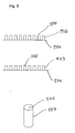
- FIG. 1 A development of the invention is shown schematically in FIG.
- the electrode head 607 with the distal end of an electrode line cord connected via a connecting line 605.
- the electrode lead In the area of distal end 600, the electrode lead has a surface area 603 a microstructure.
- the surface area 603 is circumferential in this example formed in the circumferential direction.
- the connection line 605 with a sealant 604, such as a silicone sealant, sealed against the electrode lead body at the distal end.
- Both the electrode 607 and the surface area 603 at the distal end 600 of the electrode line have a microstructure 603, which by microstructure elements is formed.
- the microstructure elements of the microstructure 602 are preferably formed electrically conductive, for example, the electrode head 607 contain the electrode lead material and a gold or platinum layer have on the surface.
- the gold or platinum layer can be vapor-deposited or sputtered on.
- This embodiment advantageously allows a relative movement along the electrode line longitudinal axis between the electrode head 607th and the distal end 600 of the electrode lead.
- the microstructural elements of Microstructures 602 and 603 may be in the form of micro-bristles, burls or scales one or a combination of the previously described embodiments and arrangements be realized.
- the electrode line has an electrode head analogous to FIG has no microstructure. The electrode head is thus free as one floating electrode, preferably as a ventricular electrode formed.
- the microstructure of the surface area the electrode line is formed such that body tissue in the surface area can grow in.
Landscapes
- Health & Medical Sciences (AREA)
- Heart & Thoracic Surgery (AREA)
- Cardiology (AREA)
- Life Sciences & Earth Sciences (AREA)
- General Health & Medical Sciences (AREA)
- Biomedical Technology (AREA)
- Nuclear Medicine, Radiotherapy & Molecular Imaging (AREA)
- Radiology & Medical Imaging (AREA)
- Vascular Medicine (AREA)
- Animal Behavior & Ethology (AREA)
- Engineering & Computer Science (AREA)
- Public Health (AREA)
- Veterinary Medicine (AREA)
- Electrotherapy Devices (AREA)
- Coils Or Transformers For Communication (AREA)
- Fixed Capacitors And Capacitor Manufacturing Machines (AREA)
- Printers Or Recording Devices Using Electromagnetic And Radiation Means (AREA)
Applications Claiming Priority (2)
| Application Number | Priority Date | Filing Date | Title |
|---|---|---|---|
| DE10331106 | 2003-07-04 | ||
| DE10331106A DE10331106A1 (de) | 2003-07-04 | 2003-07-04 | Elektrodenleitung |
Publications (2)
| Publication Number | Publication Date |
|---|---|
| EP1493463A1 true EP1493463A1 (fr) | 2005-01-05 |
| EP1493463B1 EP1493463B1 (fr) | 2007-04-04 |
Family
ID=33426889
Family Applications (1)
| Application Number | Title | Priority Date | Filing Date |
|---|---|---|---|
| EP04090230A Expired - Lifetime EP1493463B1 (fr) | 2003-07-04 | 2004-06-10 | Fil d' electrode |
Country Status (4)
| Country | Link |
|---|---|
| US (2) | US7239924B2 (fr) |
| EP (1) | EP1493463B1 (fr) |
| AT (1) | ATE358509T1 (fr) |
| DE (2) | DE10331106A1 (fr) |
Cited By (1)
| Publication number | Priority date | Publication date | Assignee | Title |
|---|---|---|---|---|
| WO2006009581A1 (fr) * | 2004-06-17 | 2006-01-26 | Medtronic, Inc. | Nouvel organe de retenue de fil guide |
Families Citing this family (18)
| Publication number | Priority date | Publication date | Assignee | Title |
|---|---|---|---|---|
| US6999819B2 (en) | 2001-08-31 | 2006-02-14 | Medtronic, Inc. | Implantable medical electrical stimulation lead fixation method and apparatus |
| US7596408B2 (en) * | 2002-12-09 | 2009-09-29 | Medtronic, Inc. | Implantable medical device with anti-infection agent |
| US7933661B2 (en) | 2004-02-04 | 2011-04-26 | Medtronic, Inc. | Lead retention means |
| US8180462B2 (en) | 2006-04-18 | 2012-05-15 | Cyberonics, Inc. | Heat dissipation for a lead assembly |
| US8478420B2 (en) | 2006-07-12 | 2013-07-02 | Cyberonics, Inc. | Implantable medical device charge balance assessment |
| US20080027524A1 (en) | 2006-07-26 | 2008-01-31 | Maschino Steven E | Multi-electrode assembly for an implantable medical device |
| US7974707B2 (en) * | 2007-01-26 | 2011-07-05 | Cyberonics, Inc. | Electrode assembly with fibers for a medical device |
| DE102007024238A1 (de) * | 2007-05-18 | 2008-11-20 | Fraunhofer-Gesellschaft zur Förderung der angewandten Forschung e.V. | Selbsthaftendes Sensorelement |
| US8868203B2 (en) | 2007-10-26 | 2014-10-21 | Cyberonics, Inc. | Dynamic lead condition detection for an implantable medical device |
| US8942798B2 (en) | 2007-10-26 | 2015-01-27 | Cyberonics, Inc. | Alternative operation mode for an implantable medical device based upon lead condition |
| US20100010520A1 (en) | 2008-07-11 | 2010-01-14 | Olympus Medical Systems Corp. | Tissue fastener |
| US9393432B2 (en) | 2008-10-31 | 2016-07-19 | Medtronic, Inc. | Non-hermetic direct current interconnect |
| US8478428B2 (en) | 2010-04-23 | 2013-07-02 | Cyberonics, Inc. | Helical electrode for nerve stimulation |
| EP2992925B1 (fr) | 2014-09-04 | 2022-09-07 | BIOTRONIK SE & Co. KG | Fil d'électrode intravasculaire et dispositif de stimulation intravasculaire comprenant celui-ci |
| EP3100762B1 (fr) * | 2015-06-02 | 2020-04-01 | BIOTRONIK SE & Co. KG | Produit medical diagnostic comprenant une structure de surface adhesive |
| US10092764B2 (en) * | 2015-08-20 | 2018-10-09 | Cardiac Pacemakers, Inc. | Implantable medical device with modified surface texture |
| DE102021100688B4 (de) | 2021-01-14 | 2024-06-13 | Osypka Ag | Elektromedizinische Elektrode |
| WO2022152470A1 (fr) | 2021-01-15 | 2022-07-21 | Biotronik Se & Co. Kg | Élément d'ancrage d'implant médical présentant des caractéristiques améliorées d'implantation et de rétention |
Citations (5)
| Publication number | Priority date | Publication date | Assignee | Title |
|---|---|---|---|---|
| EP0653223A2 (fr) * | 1993-11-02 | 1995-05-17 | Incontrol, Inc. | Conducteur implantable à extrémité distale servant de guide directionnel |
| WO1997031678A1 (fr) | 1996-03-01 | 1997-09-04 | BIOTRONIK MESS- UND THERAPIEGERäTE GMBH & CO. INGENIEURBüRO BERLIN | Systeme d'electrodes |
| US5951597A (en) * | 1998-04-14 | 1999-09-14 | Cardiac Pacemakers, Inc. | Coronary sinus lead having expandable matrix anchor |
| US5954761A (en) * | 1997-03-25 | 1999-09-21 | Intermedics Inc. | Implantable endocardial lead assembly having a stent |
| DE69430417T2 (de) | 1993-12-03 | 2002-11-28 | St. Jude Medical Ab, Jaerfaella | Elektrodensystem |
Family Cites Families (11)
| Publication number | Priority date | Publication date | Assignee | Title |
|---|---|---|---|---|
| US4030509A (en) * | 1975-09-30 | 1977-06-21 | Mieczyslaw Mirowski | Implantable electrodes for accomplishing ventricular defibrillation and pacing and method of electrode implantation and utilization |
| DE3015260A1 (de) * | 1980-04-21 | 1981-10-22 | Siemens AG, 1000 Berlin und 8000 München | Endocard-elektrodenanordnung |
| US4716888A (en) * | 1985-06-17 | 1988-01-05 | Cordis Corporation | Tined leads |
| ATE255361T1 (de) * | 1993-10-01 | 2003-12-15 | Target Therapeutics Inc | Mehrpoliger katheter und mehrpoliger führungsdraht zur messung der elektrischen herzaktivität |
| US5571162A (en) * | 1995-06-07 | 1996-11-05 | Intermedics, Inc. | Transvenous defibrillation lead with side hooks |
| US6304786B1 (en) * | 1999-03-29 | 2001-10-16 | Cardiac Pacemakers, Inc. | Implantable lead with dissolvable coating for improved fixation and extraction |
| US7083648B2 (en) * | 2000-10-31 | 2006-08-01 | East Carolina University | Tissue lockable connecting structures |
| US6551278B1 (en) * | 2000-11-10 | 2003-04-22 | Scimed Life Systems, Inc. | Miniature x-ray catheter with retractable needles or suction means for positioning at a desired site |
| US20020072737A1 (en) * | 2000-12-08 | 2002-06-13 | Medtronic, Inc. | System and method for placing a medical electrical lead |
| US7493175B2 (en) * | 2003-04-11 | 2009-02-17 | Cardiac Pacemakers, Inc. | Subcutaneous lead with tined fixation |
| US7212869B2 (en) * | 2004-02-04 | 2007-05-01 | Medtronic, Inc. | Lead retention means |
-
2003
- 2003-07-04 DE DE10331106A patent/DE10331106A1/de not_active Withdrawn
-
2004
- 2004-06-10 DE DE502004003373T patent/DE502004003373D1/de not_active Expired - Lifetime
- 2004-06-10 AT AT04090230T patent/ATE358509T1/de not_active IP Right Cessation
- 2004-06-10 EP EP04090230A patent/EP1493463B1/fr not_active Expired - Lifetime
- 2004-06-30 US US10/883,030 patent/US7239924B2/en not_active Expired - Lifetime
-
2007
- 2007-04-10 US US11/733,261 patent/US20070185557A1/en not_active Abandoned
Patent Citations (5)
| Publication number | Priority date | Publication date | Assignee | Title |
|---|---|---|---|---|
| EP0653223A2 (fr) * | 1993-11-02 | 1995-05-17 | Incontrol, Inc. | Conducteur implantable à extrémité distale servant de guide directionnel |
| DE69430417T2 (de) | 1993-12-03 | 2002-11-28 | St. Jude Medical Ab, Jaerfaella | Elektrodensystem |
| WO1997031678A1 (fr) | 1996-03-01 | 1997-09-04 | BIOTRONIK MESS- UND THERAPIEGERäTE GMBH & CO. INGENIEURBüRO BERLIN | Systeme d'electrodes |
| US5954761A (en) * | 1997-03-25 | 1999-09-21 | Intermedics Inc. | Implantable endocardial lead assembly having a stent |
| US5951597A (en) * | 1998-04-14 | 1999-09-14 | Cardiac Pacemakers, Inc. | Coronary sinus lead having expandable matrix anchor |
Cited By (1)
| Publication number | Priority date | Publication date | Assignee | Title |
|---|---|---|---|---|
| WO2006009581A1 (fr) * | 2004-06-17 | 2006-01-26 | Medtronic, Inc. | Nouvel organe de retenue de fil guide |
Also Published As
| Publication number | Publication date |
|---|---|
| ATE358509T1 (de) | 2007-04-15 |
| US20050004640A1 (en) | 2005-01-06 |
| US20070185557A1 (en) | 2007-08-09 |
| EP1493463B1 (fr) | 2007-04-04 |
| DE10331106A1 (de) | 2005-01-27 |
| US7239924B2 (en) | 2007-07-03 |
| DE502004003373D1 (de) | 2007-05-16 |
Similar Documents
| Publication | Publication Date | Title |
|---|---|---|
| EP1493463B1 (fr) | Fil d' electrode | |
| DE69223264T2 (de) | Implantierbare leitung | |
| DE69730043T2 (de) | Implantierbare eletrodenleitung | |
| DE69325846T2 (de) | Sonde für Herzschrittmacher | |
| DE69314383T2 (de) | Elektrode zur hochwirksamen Reizung von Gewebe und zur Aufnahme von Signalen | |
| DE69627290T2 (de) | Implantierbares Elektrodenkabel mit mindestens einem Elektrodenkontakt | |
| DE69603191T2 (de) | Transvenöse defibrillierungsleitung mit seitenhaken | |
| DE60017716T2 (de) | Coextrudierte medizinische multilumenleitung | |
| DE102018111178A1 (de) | Elektrodenleitung mit Fixiereinrichtung | |
| DE69329919T2 (de) | Flexibler Elektrodenkopf für eine Leitung einer implantierbaren Vorrichtung | |
| DE602004005066T2 (de) | Implantierbare medizinische leitung und herstellungsverfahren | |
| EP1839700A2 (fr) | Dispositif d'électrode médical implantable | |
| DE69518320T2 (de) | Örtlich biegsame dilatorhülse | |
| DE60212046T2 (de) | Implantierbare Elektrodenzuleitung | |
| EP1832309B1 (fr) | Dispositif médical implantable à électrodes, en particulier dispositif de défibrillation ou de stimulation cardiovasculaire à électrodes | |
| EP1129745A2 (fr) | Structure d'électrode | |
| DE10323016A1 (de) | Epicard-Elektrode | |
| EP0795344A2 (fr) | Dispositif implantable | |
| WO2010128150A1 (fr) | Instrument médical | |
| WO2004098442A1 (fr) | Implant osseux inserable par vissage | |
| EP3106201B1 (fr) | Manchon de fixation d'electrodes comprenant une structure de surface adhesive | |
| DE10114725A1 (de) | Intravaskuläre Elektrodenleitung | |
| AT512534B1 (de) | Nerven-Cuff-Elektrodenanordnung | |
| DE102019104641A1 (de) | Zugkraftverstärkungsschlauch für eine implantierbare Elektrodenleitung oder einen Katheter, Elektrodenleitung mit einem Zugkraftverstärkungsschlauch und Katheter mit einem Zugkraftverstärkungsschlauch | |
| DE10142834A1 (de) | Einzel-Elektrodensonde für Herzschrittmachersysteme |
Legal Events
| Date | Code | Title | Description |
|---|---|---|---|
| PUAI | Public reference made under article 153(3) epc to a published international application that has entered the european phase |
Free format text: ORIGINAL CODE: 0009012 |
|
| AK | Designated contracting states |
Kind code of ref document: A1 Designated state(s): AT BE BG CH CY CZ DE DK EE ES FI FR GB GR HU IE IT LI LU MC NL PL PT RO SE SI SK TR |
|
| AX | Request for extension of the european patent |
Extension state: AL HR LT LV MK |
|
| 17P | Request for examination filed |
Effective date: 20050705 |
|
| AKX | Designation fees paid |
Designated state(s): AT BE BG CH CY CZ DE DK EE ES FI FR GB GR HU IE IT LI LU MC NL PL PT RO SE SI SK TR |
|
| GRAP | Despatch of communication of intention to grant a patent |
Free format text: ORIGINAL CODE: EPIDOSNIGR1 |
|
| GRAS | Grant fee paid |
Free format text: ORIGINAL CODE: EPIDOSNIGR3 |
|
| GRAA | (expected) grant |
Free format text: ORIGINAL CODE: 0009210 |
|
| AK | Designated contracting states |
Kind code of ref document: B1 Designated state(s): AT BE BG CH CY CZ DE DK EE ES FI FR GB GR HU IE IT LI LU MC NL PL PT RO SE SI SK TR |
|
| PG25 | Lapsed in a contracting state [announced via postgrant information from national office to epo] |
Ref country code: SI Free format text: LAPSE BECAUSE OF FAILURE TO SUBMIT A TRANSLATION OF THE DESCRIPTION OR TO PAY THE FEE WITHIN THE PRESCRIBED TIME-LIMIT Effective date: 20070404 Ref country code: FI Free format text: LAPSE BECAUSE OF FAILURE TO SUBMIT A TRANSLATION OF THE DESCRIPTION OR TO PAY THE FEE WITHIN THE PRESCRIBED TIME-LIMIT Effective date: 20070404 |
|
| REG | Reference to a national code |
Ref country code: GB Ref legal event code: FG4D Free format text: NOT ENGLISH |
|
| REG | Reference to a national code |
Ref country code: CH Ref legal event code: EP |
|
| REG | Reference to a national code |
Ref country code: SE Ref legal event code: TRGR |
|
| REF | Corresponds to: |
Ref document number: 502004003373 Country of ref document: DE Date of ref document: 20070516 Kind code of ref document: P |
|
| REG | Reference to a national code |
Ref country code: IE Ref legal event code: FG4D Free format text: LANGUAGE OF EP DOCUMENT: GERMAN |
|
| GBT | Gb: translation of ep patent filed (gb section 77(6)(a)/1977) |
Effective date: 20070427 |
|
| PG25 | Lapsed in a contracting state [announced via postgrant information from national office to epo] |
Ref country code: ES Free format text: LAPSE BECAUSE OF FAILURE TO SUBMIT A TRANSLATION OF THE DESCRIPTION OR TO PAY THE FEE WITHIN THE PRESCRIBED TIME-LIMIT Effective date: 20070715 |
|
| ET | Fr: translation filed | ||
| PG25 | Lapsed in a contracting state [announced via postgrant information from national office to epo] |
Ref country code: PT Free format text: LAPSE BECAUSE OF FAILURE TO SUBMIT A TRANSLATION OF THE DESCRIPTION OR TO PAY THE FEE WITHIN THE PRESCRIBED TIME-LIMIT Effective date: 20070904 |
|
| PG25 | Lapsed in a contracting state [announced via postgrant information from national office to epo] |
Ref country code: PL Free format text: LAPSE BECAUSE OF FAILURE TO SUBMIT A TRANSLATION OF THE DESCRIPTION OR TO PAY THE FEE WITHIN THE PRESCRIBED TIME-LIMIT Effective date: 20070404 |
|
| BERE | Be: lapsed |
Owner name: BIOTRONIK G.M.B.H. & CO. KG Effective date: 20070630 |
|
| PG25 | Lapsed in a contracting state [announced via postgrant information from national office to epo] |
Ref country code: CZ Free format text: LAPSE BECAUSE OF FAILURE TO SUBMIT A TRANSLATION OF THE DESCRIPTION OR TO PAY THE FEE WITHIN THE PRESCRIBED TIME-LIMIT Effective date: 20070404 Ref country code: MC Free format text: LAPSE BECAUSE OF NON-PAYMENT OF DUE FEES Effective date: 20070630 Ref country code: BG Free format text: LAPSE BECAUSE OF FAILURE TO SUBMIT A TRANSLATION OF THE DESCRIPTION OR TO PAY THE FEE WITHIN THE PRESCRIBED TIME-LIMIT Effective date: 20070704 Ref country code: DK Free format text: LAPSE BECAUSE OF FAILURE TO SUBMIT A TRANSLATION OF THE DESCRIPTION OR TO PAY THE FEE WITHIN THE PRESCRIBED TIME-LIMIT Effective date: 20070404 |
|
| PLBE | No opposition filed within time limit |
Free format text: ORIGINAL CODE: 0009261 |
|
| STAA | Information on the status of an ep patent application or granted ep patent |
Free format text: STATUS: NO OPPOSITION FILED WITHIN TIME LIMIT |
|
| PG25 | Lapsed in a contracting state [announced via postgrant information from national office to epo] |
Ref country code: SK Free format text: LAPSE BECAUSE OF FAILURE TO SUBMIT A TRANSLATION OF THE DESCRIPTION OR TO PAY THE FEE WITHIN THE PRESCRIBED TIME-LIMIT Effective date: 20070404 |
|
| 26N | No opposition filed |
Effective date: 20080107 |
|
| PG25 | Lapsed in a contracting state [announced via postgrant information from national office to epo] |
Ref country code: BE Free format text: LAPSE BECAUSE OF NON-PAYMENT OF DUE FEES Effective date: 20070630 |
|
| PG25 | Lapsed in a contracting state [announced via postgrant information from national office to epo] |
Ref country code: GR Free format text: LAPSE BECAUSE OF FAILURE TO SUBMIT A TRANSLATION OF THE DESCRIPTION OR TO PAY THE FEE WITHIN THE PRESCRIBED TIME-LIMIT Effective date: 20070705 Ref country code: IT Free format text: LAPSE BECAUSE OF FAILURE TO SUBMIT A TRANSLATION OF THE DESCRIPTION OR TO PAY THE FEE WITHIN THE PRESCRIBED TIME-LIMIT Effective date: 20070404 |
|
| PG25 | Lapsed in a contracting state [announced via postgrant information from national office to epo] |
Ref country code: RO Free format text: LAPSE BECAUSE OF FAILURE TO SUBMIT A TRANSLATION OF THE DESCRIPTION OR TO PAY THE FEE WITHIN THE PRESCRIBED TIME-LIMIT Effective date: 20070404 |
|
| PG25 | Lapsed in a contracting state [announced via postgrant information from national office to epo] |
Ref country code: AT Free format text: LAPSE BECAUSE OF NON-PAYMENT OF DUE FEES Effective date: 20070610 |
|
| PGFP | Annual fee paid to national office [announced via postgrant information from national office to epo] |
Ref country code: NL Payment date: 20080618 Year of fee payment: 5 |
|
| PG25 | Lapsed in a contracting state [announced via postgrant information from national office to epo] |
Ref country code: EE Free format text: LAPSE BECAUSE OF FAILURE TO SUBMIT A TRANSLATION OF THE DESCRIPTION OR TO PAY THE FEE WITHIN THE PRESCRIBED TIME-LIMIT Effective date: 20070404 |
|
| PG25 | Lapsed in a contracting state [announced via postgrant information from national office to epo] |
Ref country code: CY Free format text: LAPSE BECAUSE OF FAILURE TO SUBMIT A TRANSLATION OF THE DESCRIPTION OR TO PAY THE FEE WITHIN THE PRESCRIBED TIME-LIMIT Effective date: 20070404 |
|
| PG25 | Lapsed in a contracting state [announced via postgrant information from national office to epo] |
Ref country code: LU Free format text: LAPSE BECAUSE OF NON-PAYMENT OF DUE FEES Effective date: 20070610 |
|
| PG25 | Lapsed in a contracting state [announced via postgrant information from national office to epo] |
Ref country code: TR Free format text: LAPSE BECAUSE OF FAILURE TO SUBMIT A TRANSLATION OF THE DESCRIPTION OR TO PAY THE FEE WITHIN THE PRESCRIBED TIME-LIMIT Effective date: 20070404 Ref country code: HU Free format text: LAPSE BECAUSE OF FAILURE TO SUBMIT A TRANSLATION OF THE DESCRIPTION OR TO PAY THE FEE WITHIN THE PRESCRIBED TIME-LIMIT Effective date: 20071005 |
|
| NLV4 | Nl: lapsed or anulled due to non-payment of the annual fee |
Effective date: 20100101 |
|
| PG25 | Lapsed in a contracting state [announced via postgrant information from national office to epo] |
Ref country code: NL Free format text: LAPSE BECAUSE OF NON-PAYMENT OF DUE FEES Effective date: 20100101 |
|
| REG | Reference to a national code |
Ref legal event code: R082 Country of ref document: DE Representative=s name: RANDOLL, SOEREN, DIPL.-CHEM. UNIV. DR. RER. NA, DE Ref country code: DE Ref document number: 502004003373 |
|
| REG | Reference to a national code |
Ref country code: DE Ref legal event code: R081 Ref document number: 502004003373 Country of ref document: DE Owner name: BIOTRONIK SE & CO. KG, DE Free format text: FORMER OWNER: BIOTRONIK GMBH & CO. KG, 12359 BERLIN, DE Effective date: 20111219 |
|
| PGFP | Annual fee paid to national office [announced via postgrant information from national office to epo] |
Ref country code: SE Payment date: 20120625 Year of fee payment: 9 Ref country code: GB Payment date: 20120621 Year of fee payment: 9 |
|
| PGFP | Annual fee paid to national office [announced via postgrant information from national office to epo] |
Ref country code: FR Payment date: 20130703 Year of fee payment: 10 |
|
| PG25 | Lapsed in a contracting state [announced via postgrant information from national office to epo] |
Ref country code: SE Free format text: LAPSE BECAUSE OF NON-PAYMENT OF DUE FEES Effective date: 20130611 |
|
| REG | Reference to a national code |
Ref country code: SE Ref legal event code: EUG |
|
| GBPC | Gb: european patent ceased through non-payment of renewal fee |
Effective date: 20130610 |
|
| PG25 | Lapsed in a contracting state [announced via postgrant information from national office to epo] |
Ref country code: GB Free format text: LAPSE BECAUSE OF NON-PAYMENT OF DUE FEES Effective date: 20130610 |
|
| REG | Reference to a national code |
Ref country code: FR Ref legal event code: ST Effective date: 20150227 |
|
| PG25 | Lapsed in a contracting state [announced via postgrant information from national office to epo] |
Ref country code: FR Free format text: LAPSE BECAUSE OF NON-PAYMENT OF DUE FEES Effective date: 20140630 |
|
| PGFP | Annual fee paid to national office [announced via postgrant information from national office to epo] |
Ref country code: DE Payment date: 20210625 Year of fee payment: 18 |
|
| PGFP | Annual fee paid to national office [announced via postgrant information from national office to epo] |
Ref country code: CH Payment date: 20210623 Year of fee payment: 18 Ref country code: IE Payment date: 20210622 Year of fee payment: 18 |
|
| REG | Reference to a national code |
Ref country code: DE Ref legal event code: R119 Ref document number: 502004003373 Country of ref document: DE |
|
| REG | Reference to a national code |
Ref country code: CH Ref legal event code: PL |
|
| PG25 | Lapsed in a contracting state [announced via postgrant information from national office to epo] |
Ref country code: LI Free format text: LAPSE BECAUSE OF NON-PAYMENT OF DUE FEES Effective date: 20220630 Ref country code: IE Free format text: LAPSE BECAUSE OF NON-PAYMENT OF DUE FEES Effective date: 20220610 Ref country code: CH Free format text: LAPSE BECAUSE OF NON-PAYMENT OF DUE FEES Effective date: 20220630 |
|
| PG25 | Lapsed in a contracting state [announced via postgrant information from national office to epo] |
Ref country code: DE Free format text: LAPSE BECAUSE OF NON-PAYMENT OF DUE FEES Effective date: 20230103 |