EP1493487A1 - Système microfluidique avec régulation du courant ESI résiduel - Google Patents
Système microfluidique avec régulation du courant ESI résiduel Download PDFInfo
- Publication number
- EP1493487A1 EP1493487A1 EP04103981A EP04103981A EP1493487A1 EP 1493487 A1 EP1493487 A1 EP 1493487A1 EP 04103981 A EP04103981 A EP 04103981A EP 04103981 A EP04103981 A EP 04103981A EP 1493487 A1 EP1493487 A1 EP 1493487A1
- Authority
- EP
- European Patent Office
- Prior art keywords
- channel
- electrode
- fluid
- measuring
- channels
- Prior art date
- Legal status (The legal status is an assumption and is not a legal conclusion. Google has not performed a legal analysis and makes no representation as to the accuracy of the status listed.)
- Withdrawn
Links
- 239000012530 fluid Substances 0.000 claims abstract description 56
- 238000000034 method Methods 0.000 claims abstract description 18
- 230000005684 electric field Effects 0.000 claims abstract description 13
- 239000007921 spray Substances 0.000 claims abstract description 7
- 238000000926 separation method Methods 0.000 claims description 23
- 238000004891 communication Methods 0.000 claims description 6
- 230000001419 dependent effect Effects 0.000 claims description 2
- 239000000523 sample Substances 0.000 claims 3
- 230000008569 process Effects 0.000 abstract description 4
- 238000001962 electrophoresis Methods 0.000 abstract description 3
- 238000002347 injection Methods 0.000 description 19
- 239000007924 injection Substances 0.000 description 19
- 238000004458 analytical method Methods 0.000 description 12
- 239000000126 substance Substances 0.000 description 12
- 230000007704 transition Effects 0.000 description 8
- 230000008859 change Effects 0.000 description 7
- 239000002699 waste material Substances 0.000 description 7
- 239000000872 buffer Substances 0.000 description 5
- 230000001276 controlling effect Effects 0.000 description 5
- 239000007788 liquid Substances 0.000 description 5
- 239000000470 constituent Substances 0.000 description 4
- 230000008901 benefit Effects 0.000 description 3
- 230000001105 regulatory effect Effects 0.000 description 3
- 238000004611 spectroscopical analysis Methods 0.000 description 3
- 238000012937 correction Methods 0.000 description 2
- 238000013461 design Methods 0.000 description 2
- 238000001514 detection method Methods 0.000 description 2
- 238000005516 engineering process Methods 0.000 description 2
- 230000002349 favourable effect Effects 0.000 description 2
- 239000000463 material Substances 0.000 description 2
- 238000001228 spectrum Methods 0.000 description 2
- FIKFLLIUPUVONI-UHFFFAOYSA-N 8-(2-phenylethyl)-1-oxa-3,8-diazaspiro[4.5]decan-2-one;hydrochloride Chemical compound Cl.O1C(=O)NCC11CCN(CCC=2C=CC=CC=2)CC1 FIKFLLIUPUVONI-UHFFFAOYSA-N 0.000 description 1
- 238000010521 absorption reaction Methods 0.000 description 1
- 230000003044 adaptive effect Effects 0.000 description 1
- 239000012491 analyte Substances 0.000 description 1
- 238000003556 assay Methods 0.000 description 1
- 230000015572 biosynthetic process Effects 0.000 description 1
- 239000007853 buffer solution Substances 0.000 description 1
- 238000005251 capillar electrophoresis Methods 0.000 description 1
- 238000003981 capillary liquid chromatography Methods 0.000 description 1
- 238000006243 chemical reaction Methods 0.000 description 1
- 238000005370 electroosmosis Methods 0.000 description 1
- 230000008030 elimination Effects 0.000 description 1
- 238000003379 elimination reaction Methods 0.000 description 1
- 238000011156 evaluation Methods 0.000 description 1
- 150000002500 ions Chemical class 0.000 description 1
- 238000004949 mass spectrometry Methods 0.000 description 1
- 238000005259 measurement Methods 0.000 description 1
- 230000007246 mechanism Effects 0.000 description 1
- 238000013508 migration Methods 0.000 description 1
- 230000005012 migration Effects 0.000 description 1
- 230000007935 neutral effect Effects 0.000 description 1
- 230000003647 oxidation Effects 0.000 description 1
- 238000007254 oxidation reaction Methods 0.000 description 1
- 239000002245 particle Substances 0.000 description 1
- 230000035515 penetration Effects 0.000 description 1
- 238000002731 protein assay Methods 0.000 description 1
- 230000004044 response Effects 0.000 description 1
- 230000035945 sensitivity Effects 0.000 description 1
- 239000000243 solution Substances 0.000 description 1
- 239000000758 substrate Substances 0.000 description 1
- 238000010998 test method Methods 0.000 description 1
- 238000012360 testing method Methods 0.000 description 1
- 238000012549 training Methods 0.000 description 1
- 238000012546 transfer Methods 0.000 description 1
Images


Classifications
-
- B—PERFORMING OPERATIONS; TRANSPORTING
- B01—PHYSICAL OR CHEMICAL PROCESSES OR APPARATUS IN GENERAL
- B01L—CHEMICAL OR PHYSICAL LABORATORY APPARATUS FOR GENERAL USE
- B01L3/00—Containers or dishes for laboratory use, e.g. laboratory glassware; Droppers
- B01L3/50—Containers for the purpose of retaining a material to be analysed, e.g. test tubes
- B01L3/502—Containers for the purpose of retaining a material to be analysed, e.g. test tubes with fluid transport, e.g. in multi-compartment structures
- B01L3/5027—Containers for the purpose of retaining a material to be analysed, e.g. test tubes with fluid transport, e.g. in multi-compartment structures by integrated microfluidic structures, i.e. dimensions of channels and chambers are such that surface tension forces are important, e.g. lab-on-a-chip
- B01L3/50273—Containers for the purpose of retaining a material to be analysed, e.g. test tubes with fluid transport, e.g. in multi-compartment structures by integrated microfluidic structures, i.e. dimensions of channels and chambers are such that surface tension forces are important, e.g. lab-on-a-chip characterised by the means or forces applied to move the fluids
-
- B—PERFORMING OPERATIONS; TRANSPORTING
- B01—PHYSICAL OR CHEMICAL PROCESSES OR APPARATUS IN GENERAL
- B01L—CHEMICAL OR PHYSICAL LABORATORY APPARATUS FOR GENERAL USE
- B01L3/00—Containers or dishes for laboratory use, e.g. laboratory glassware; Droppers
- B01L3/50—Containers for the purpose of retaining a material to be analysed, e.g. test tubes
- B01L3/502—Containers for the purpose of retaining a material to be analysed, e.g. test tubes with fluid transport, e.g. in multi-compartment structures
- B01L3/5027—Containers for the purpose of retaining a material to be analysed, e.g. test tubes with fluid transport, e.g. in multi-compartment structures by integrated microfluidic structures, i.e. dimensions of channels and chambers are such that surface tension forces are important, e.g. lab-on-a-chip
- B01L3/502715—Containers for the purpose of retaining a material to be analysed, e.g. test tubes with fluid transport, e.g. in multi-compartment structures by integrated microfluidic structures, i.e. dimensions of channels and chambers are such that surface tension forces are important, e.g. lab-on-a-chip characterised by interfacing components, e.g. fluidic, electrical, optical or mechanical interfaces
-
- G—PHYSICS
- G01—MEASURING; TESTING
- G01N—INVESTIGATING OR ANALYSING MATERIALS BY DETERMINING THEIR CHEMICAL OR PHYSICAL PROPERTIES
- G01N27/00—Investigating or analysing materials by the use of electric, electrochemical, or magnetic means
- G01N27/26—Investigating or analysing materials by the use of electric, electrochemical, or magnetic means by investigating electrochemical variables; by using electrolysis or electrophoresis
- G01N27/416—Systems
- G01N27/447—Systems using electrophoresis
- G01N27/44704—Details; Accessories
-
- G—PHYSICS
- G01—MEASURING; TESTING
- G01N—INVESTIGATING OR ANALYSING MATERIALS BY DETERMINING THEIR CHEMICAL OR PHYSICAL PROPERTIES
- G01N27/00—Investigating or analysing materials by the use of electric, electrochemical, or magnetic means
- G01N27/26—Investigating or analysing materials by the use of electric, electrochemical, or magnetic means by investigating electrochemical variables; by using electrolysis or electrophoresis
- G01N27/416—Systems
- G01N27/447—Systems using electrophoresis
- G01N27/44704—Details; Accessories
- G01N27/44717—Arrangements for investigating the separated zones, e.g. localising zones
-
- G—PHYSICS
- G01—MEASURING; TESTING
- G01N—INVESTIGATING OR ANALYSING MATERIALS BY DETERMINING THEIR CHEMICAL OR PHYSICAL PROPERTIES
- G01N27/00—Investigating or analysing materials by the use of electric, electrochemical, or magnetic means
- G01N27/26—Investigating or analysing materials by the use of electric, electrochemical, or magnetic means by investigating electrochemical variables; by using electrolysis or electrophoresis
- G01N27/416—Systems
- G01N27/447—Systems using electrophoresis
- G01N27/44704—Details; Accessories
- G01N27/44752—Controlling the zeta potential, e.g. by wall coatings
-
- G—PHYSICS
- G01—MEASURING; TESTING
- G01N—INVESTIGATING OR ANALYSING MATERIALS BY DETERMINING THEIR CHEMICAL OR PHYSICAL PROPERTIES
- G01N27/00—Investigating or analysing materials by the use of electric, electrochemical, or magnetic means
- G01N27/26—Investigating or analysing materials by the use of electric, electrochemical, or magnetic means by investigating electrochemical variables; by using electrolysis or electrophoresis
- G01N27/416—Systems
- G01N27/447—Systems using electrophoresis
- G01N27/44756—Apparatus specially adapted therefor
- G01N27/44791—Microapparatus
-
- B—PERFORMING OPERATIONS; TRANSPORTING
- B01—PHYSICAL OR CHEMICAL PROCESSES OR APPARATUS IN GENERAL
- B01L—CHEMICAL OR PHYSICAL LABORATORY APPARATUS FOR GENERAL USE
- B01L2200/00—Solutions for specific problems relating to chemical or physical laboratory apparatus
- B01L2200/14—Process control and prevention of errors
- B01L2200/143—Quality control, feedback systems
-
- B—PERFORMING OPERATIONS; TRANSPORTING
- B01—PHYSICAL OR CHEMICAL PROCESSES OR APPARATUS IN GENERAL
- B01L—CHEMICAL OR PHYSICAL LABORATORY APPARATUS FOR GENERAL USE
- B01L2300/00—Additional constructional details
- B01L2300/06—Auxiliary integrated devices, integrated components
- B01L2300/0627—Sensor or part of a sensor is integrated
- B01L2300/0645—Electrodes
-
- B—PERFORMING OPERATIONS; TRANSPORTING
- B01—PHYSICAL OR CHEMICAL PROCESSES OR APPARATUS IN GENERAL
- B01L—CHEMICAL OR PHYSICAL LABORATORY APPARATUS FOR GENERAL USE
- B01L2300/00—Additional constructional details
- B01L2300/08—Geometry, shape and general structure
- B01L2300/0809—Geometry, shape and general structure rectangular shaped
- B01L2300/0816—Cards, e.g. flat sample carriers usually with flow in two horizontal directions
-
- B—PERFORMING OPERATIONS; TRANSPORTING
- B01—PHYSICAL OR CHEMICAL PROCESSES OR APPARATUS IN GENERAL
- B01L—CHEMICAL OR PHYSICAL LABORATORY APPARATUS FOR GENERAL USE
- B01L2300/00—Additional constructional details
- B01L2300/08—Geometry, shape and general structure
- B01L2300/0861—Configuration of multiple channels and/or chambers in a single devices
- B01L2300/0867—Multiple inlets and one sample wells, e.g. mixing, dilution
-
- B—PERFORMING OPERATIONS; TRANSPORTING
- B01—PHYSICAL OR CHEMICAL PROCESSES OR APPARATUS IN GENERAL
- B01L—CHEMICAL OR PHYSICAL LABORATORY APPARATUS FOR GENERAL USE
- B01L2400/00—Moving or stopping fluids
- B01L2400/04—Moving fluids with specific forces or mechanical means
- B01L2400/0403—Moving fluids with specific forces or mechanical means specific forces
- B01L2400/0415—Moving fluids with specific forces or mechanical means specific forces electrical forces, e.g. electrokinetic
-
- B—PERFORMING OPERATIONS; TRANSPORTING
- B01—PHYSICAL OR CHEMICAL PROCESSES OR APPARATUS IN GENERAL
- B01L—CHEMICAL OR PHYSICAL LABORATORY APPARATUS FOR GENERAL USE
- B01L2400/00—Moving or stopping fluids
- B01L2400/04—Moving fluids with specific forces or mechanical means
- B01L2400/0403—Moving fluids with specific forces or mechanical means specific forces
- B01L2400/043—Moving fluids with specific forces or mechanical means specific forces magnetic forces
-
- B—PERFORMING OPERATIONS; TRANSPORTING
- B01—PHYSICAL OR CHEMICAL PROCESSES OR APPARATUS IN GENERAL
- B01L—CHEMICAL OR PHYSICAL LABORATORY APPARATUS FOR GENERAL USE
- B01L2400/00—Moving or stopping fluids
- B01L2400/04—Moving fluids with specific forces or mechanical means
- B01L2400/0403—Moving fluids with specific forces or mechanical means specific forces
- B01L2400/0433—Moving fluids with specific forces or mechanical means specific forces vibrational forces
- B01L2400/0436—Moving fluids with specific forces or mechanical means specific forces vibrational forces acoustic forces, e.g. surface acoustic waves [SAW]
-
- B—PERFORMING OPERATIONS; TRANSPORTING
- B01—PHYSICAL OR CHEMICAL PROCESSES OR APPARATUS IN GENERAL
- B01L—CHEMICAL OR PHYSICAL LABORATORY APPARATUS FOR GENERAL USE
- B01L2400/00—Moving or stopping fluids
- B01L2400/04—Moving fluids with specific forces or mechanical means
- B01L2400/0475—Moving fluids with specific forces or mechanical means specific mechanical means and fluid pressure
- B01L2400/0487—Moving fluids with specific forces or mechanical means specific mechanical means and fluid pressure fluid pressure, pneumatics
-
- B—PERFORMING OPERATIONS; TRANSPORTING
- B01—PHYSICAL OR CHEMICAL PROCESSES OR APPARATUS IN GENERAL
- B01L—CHEMICAL OR PHYSICAL LABORATORY APPARATUS FOR GENERAL USE
- B01L3/00—Containers or dishes for laboratory use, e.g. laboratory glassware; Droppers
- B01L3/02—Burettes; Pipettes
- B01L3/0241—Drop counters; Drop formers
-
- Y—GENERAL TAGGING OF NEW TECHNOLOGICAL DEVELOPMENTS; GENERAL TAGGING OF CROSS-SECTIONAL TECHNOLOGIES SPANNING OVER SEVERAL SECTIONS OF THE IPC; TECHNICAL SUBJECTS COVERED BY FORMER USPC CROSS-REFERENCE ART COLLECTIONS [XRACs] AND DIGESTS
- Y10—TECHNICAL SUBJECTS COVERED BY FORMER USPC
- Y10T—TECHNICAL SUBJECTS COVERED BY FORMER US CLASSIFICATION
- Y10T137/00—Fluid handling
- Y10T137/0318—Processes
- Y10T137/0396—Involving pressure control
-
- Y—GENERAL TAGGING OF NEW TECHNOLOGICAL DEVELOPMENTS; GENERAL TAGGING OF CROSS-SECTIONAL TECHNOLOGIES SPANNING OVER SEVERAL SECTIONS OF THE IPC; TECHNICAL SUBJECTS COVERED BY FORMER USPC CROSS-REFERENCE ART COLLECTIONS [XRACs] AND DIGESTS
- Y10—TECHNICAL SUBJECTS COVERED BY FORMER USPC
- Y10T—TECHNICAL SUBJECTS COVERED BY FORMER US CLASSIFICATION
- Y10T137/00—Fluid handling
- Y10T137/206—Flow affected by fluid contact, energy field or coanda effect [e.g., pure fluid device or system]
- Y10T137/218—Means to regulate or vary operation of device
- Y10T137/2191—By non-fluid energy field affecting input [e.g., transducer]
-
- Y—GENERAL TAGGING OF NEW TECHNOLOGICAL DEVELOPMENTS; GENERAL TAGGING OF CROSS-SECTIONAL TECHNOLOGIES SPANNING OVER SEVERAL SECTIONS OF THE IPC; TECHNICAL SUBJECTS COVERED BY FORMER USPC CROSS-REFERENCE ART COLLECTIONS [XRACs] AND DIGESTS
- Y10—TECHNICAL SUBJECTS COVERED BY FORMER USPC
- Y10T—TECHNICAL SUBJECTS COVERED BY FORMER US CLASSIFICATION
- Y10T137/00—Fluid handling
- Y10T137/206—Flow affected by fluid contact, energy field or coanda effect [e.g., pure fluid device or system]
- Y10T137/218—Means to regulate or vary operation of device
- Y10T137/2191—By non-fluid energy field affecting input [e.g., transducer]
- Y10T137/2196—Acoustical or thermal energy
-
- Y—GENERAL TAGGING OF NEW TECHNOLOGICAL DEVELOPMENTS; GENERAL TAGGING OF CROSS-SECTIONAL TECHNOLOGIES SPANNING OVER SEVERAL SECTIONS OF THE IPC; TECHNICAL SUBJECTS COVERED BY FORMER USPC CROSS-REFERENCE ART COLLECTIONS [XRACs] AND DIGESTS
- Y10—TECHNICAL SUBJECTS COVERED BY FORMER USPC
- Y10T—TECHNICAL SUBJECTS COVERED BY FORMER US CLASSIFICATION
- Y10T137/00—Fluid handling
- Y10T137/8158—With indicator, register, recorder, alarm or inspection means
- Y10T137/8326—Fluid pressure responsive indicator, recorder or alarm
Definitions
- Microfluidic systems are known from US 5,965,001, US 5,800,690 and from Journal Electrophoresis (2000), pages 100 to 106 and pages 107 to 115 previously known. The content of these documents becomes arbitrary at this point Purposes, as important in these documents.
- Such microfluidic systems as well as possible methods for transport and the guidance of fluids and / or components contained therein in such Microfluidic systems are disclosed, so of features for which individually or in Combination with each other, in combination with the additional in this application disclosed features protection is claimed.
- a problem with the application of electrokinetic forces using of electrodes is that they are not directly in or on the microchannels of the Microfluidic system can be used as it is common on the electrodes too an undesirable gas bubble formation comes.
- these gas bubbles can be in the miniaturized channels to increase the effective resistance up lead to an infinite effective resistance.
- the electrodes are usually connected to reservoirs, which is a comparatively can absorb large volumes of fluid and those opposite the geometry the miniature channels have significantly larger dimensions. This, however, is the Use of the electrodes limited to the respective end of the miniature channels. For one however, exact and reproducible test procedures are often the electrical ones Parameters at the crossing points or those transition areas of interest, in which the individual microfluidic channels merge into one another.
- the microfluidic system is with an open network of formed fluidly interconnected channels, wherein at least three, preferably four of the channels in a common, in particular point-like open trained channel space, wherein one of the channels acts as a measuring channel.
- the microfluidic system can be particularly reach controllable substance flows via the measuring channel or the measuring channels, which allow the application of economically manageable control algorithms and the a widely used application and application spectrum of such Enable microfluidic systems.
- the controller regulates the driving force and / or thereby influenceable characteristic such that it is particularly independent of internal and / or external disturbances are kept substantially constant, so that greater reliability and a wider range of application are possible.
- Constant is within the scope of the disclosure
- This protection right is not just a constant absolute value over time meant, but any characteristic function over time, so for example a “gradient” or a “ramp”, but by the inventive control is kept invariant in response to internal or external disturbances.
- the controller is the driving force and / or the characterized controllable characteristic such that the gradient of the driving Force and / or the gradient of the influenceable by the driving force characteristic over a certain section of the working channel, in particular independently of internal and / or external disturbances, is kept substantially constant or become.
- the controller can be in the working channel a substantially constant speed or a substantially constant flow of the fluid and / or constituents contained therein, which is the case for many applications, especially interesting for applications in the field of separation analysis.
- the controller is the driving force and / or thereby controllable characteristic such that a substantially constant or predetermined Joule power dissipation is achieved so that in the fluid thread of the working channel occurring temperature is kept constant or the Temperature increase is determinable and therefore another computational Evaluation can be fed. It is useful if the scheme or the Identification of the sample components depending on the own mobility in context with the voltage applied to the separation channel differential voltage to at occurring conductivity changes an identification of the sample components to allow about their own mobility.
- microfluidic systems can be used in applications on the Area of capillary electrophoresis, liquid chromatography and chemical reactions, especially in DNA / RNA assays or protein assays with a higher operational safety against internal and / or external Use disturbance variables and in an extended range of applications and applications, which also meets current and future user needs high quality of analysis results even over a long period of time suffice.
- each other fluid-connected channels formed microfluidic system at least two channels to a common ESI (electrospray interface) point, where at least two of the channels at their respective, away from the common channel space End, each with an electrode for applying an electric field on the Fluid are contacted, and wherein the electrodes with electric current and / or electrical voltage can be acted upon, and wherein the sum of the electric Current is regulated in the entire microfluidic system such that according to the Kirchhoff law remains a certain ESI residual current.
- ESI electrospray interface
- the above features carry each other individually as well as in combination to a microfluidic system or a method of transport and guidance a fluid and / or components contained therein in such a microfluidic system that offers a wider range of applications and applications and a reduced sensitivity to internal and / or external disturbances and thus allowing greater reliability.
- the microfluidic system 10 shown in FIG. 1 includes a microfluidic chip 11. This comprises the substrate 12, in this case sixteen reservoirs 21 to 36th are taken up for the absorption of various fluid substances. There are twelve Reservoirs 21 to 32 for receiving the samples 41 to 52, a reservoir 33 for Recording a serving as a separation medium buffer 53 and the with some buffer pre-filled reservoirs 34, 35, 36 for receiving waste 54, 55, 56 are provided.
- the reservoirs 21 to 36 are fluidly interconnected by microchannels which form an open network with each other. This means that each of the Reservoirs 21 to 36 is in fluid communication with each other reservoir.
- opening channels again open in the area Transition point 66 into a single channel, located in the area of a transfer point 68 divided into two channels.
- the first channel of these two channels opens into the Reservoir 34, which serves to receive the waste 54.
- the second channel of these two Channels empties into the injection space of the injection site 65, which as shown here as two intersecting channels can be designed with a total of four channel parts.
- the junction of the channel 61 in the injection chamber opposite the working channel 70 opens.
- the injection space 65 associated injection space is in the exemplary embodiment as a crossing point of the four described above Channel parts designed in this embodiment each at an angle of 90 degrees offset from one another are arranged in a common plane, wherein the each opposite channel parts in the case shown here to each other are arranged in alignment.
- Each reservoir 21 to 36 is contacted with an electrode 71 to 86.
- These serve for the entry and exit of electrical voltage and / or electrical current and can serve according to the invention at the same time as a measuring electrode. With their help may be associated with the current performance of the microfluidic system 10 recorded electrical parameters and a controller for controlling the driving force and / or a characteristic which can be influenced thereby.
- a driving force electrokinetic forces which by introducing or exerting electrical voltages across the electrodes 71 to 86 are introduced or transferred to the respective fluids 41 to 56 can, so that the fluids or contained therein components in the of User desired direction and speed through the one open Network miniature channels can move.
- the microfluidic system 110 shown partially schematically in FIG. 2, is particularly simply designed. This figure is also used to represent the control and Control of the fluid or the components contained therein driving force and / or the characteristics that can be influenced thereby.
- the microfluidic system 110 has the one working channel 170, in which the fluid 141 and / or contained therein Components by means of a driving force, here one by the voltage source 188 generated electric or electrokinetic field in the direction (arrow 113) of the working channel 170 are movable.
- the reservoirs 121 and 135 arranged with the working channel 170 in Fluid connection stand.
- Each reservoir 121, 135 is each provided with an electrode 171 or 185 contacted for input and output of electrical characteristics.
- the fluid 141 or The components contained therein can be directed in the direction (arrow 113) of the working channel 170 are moved through this and may or may finally its waste as waste 155 enter the reservoir 135.
- the Fluid 141 or the constituents contained therein with a substantially constant speed through the working channel 170 to move to a to be able to carry out as exact an analysis as possible.
- a characteristic parameter for the identification of a sample component is the Eigenmobiltician. This substance constant leads in connection with the operating parameters field strength and Viscosity of the separation medium at a characteristic speed.
- the occurring power loss may change with the Consequence that when applying a substantially constant voltage to the Electrodes 171 and 185, according to the prior art, depending on the internal and / or external disturbances in the interior of the also referred to as fluid thread Fluid stream sets a relation to the setpoint changed temperature, so that the viscosity of the instantaneous velocity of the sample components forms in the separation channel depending on the internal and / or external disturbances.
- the electrode 185 is as Measuring electrode, i. as a sensor for measuring a fluid 141 associated or coupled to the fluid 141 and derivable in the region of the fluid 141 Measured variable, here the electric current provided.
- the controller 192 With the sensor 185 is the controller 192, here via electrical lines, coupled.
- This controller 192 obeys a predetermined mathematical algorithm 193 and may also be considered be designed programmable controller.
- the controller 192 is in turn with a Device for changing the driving force 189, here the electric Voltage coupled, which forms an actuator.
- the institution for change the driving force 189 is coupled to the voltage source 188, which the necessary electrical voltage or the necessary electric field supplies.
- Control device 191 for controlling the means for changing the driving force connected to certain preset parameters.
- certain preset parameters there it may be the one according to the prior art in a so-called "script" set parameters act.
- These can also be stored in a storage unit, be stored for example a RAM or ROM.
- the institution for change the driving force 189 is further provided with a regulator 190 for Provision of stabilized, i. essentially constant electrical Voltage or currents coupled, in turn, electrically connected to the electrode 171 is coupled.
- the controller 192 receives from the controller 190 the current Status, which by means of the predetermined mathematical algorithm 193 with Knowledge of the measured current in a current deviation of the power loss and thus can be converted into a correction value.
- This correction value is used to control the means 189 for changing the driving force used. In this way, it is possible to adapt to the current operating behavior of the Microfluidic system 110 creating adaptive superimposed control loop with which it is possible, the occurring power loss and thus in the fluid thread of the Working channel 170 occurring temperature increase independent of internal and / or external disturbances to be kept substantially constant.
- the identification of the sample components can now be expected in the constant Temperature conditions and in knowledge of the measurable voltage difference on Separation channel through a time window.
- This time window calculated from the time Injection, resulting from the corresponding mobility in the electric field over the distance in the separation channel from the injection point to the place of detection.
- the voltage source 188, the means for changing the driving force 189, the controller 191 and the controller 190 constitute the power supply unit 187. It is understood that such a power supply unit, at least the means for changing the driving force 189 and the Regulator device 190, each or all electrodes 171, 185 even at one with more designed as a two-electrode microfluidic system, according to user needs can be used multiple times. In such a case will the controller 192 also the respective status of the electrode 185 associated Control device 190a supplied.
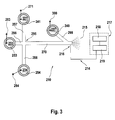
- Fig. 3 shows another microfluidic system, as it is for a mass spectroscopic Analysis of fluid substances and / or components contained therein can be used.
- the microfluidic system 210 is two at a right angle designed intersecting channels, in turn, with four channel parts 296, 297, 298 and 270 are designed.
- the channel parts 296 and 270 are aligned and the channel parts 297 and 298, respectively.
- the channel parts 296, 297, 298 and 270 each at an angle of here 90 degrees to each other in a common-seeds Level trained.
- the channel parts 296, 297, 298 and 270 intersect at the intersection 295, which has an injection space for the analyte To form a sample.
- a reservoir 233, 221 and 234 provided, which in each case with the associated channel part in fluid communication stands.
- These reservoirs 221, 233, 234 are each provided with an electrode 271, 283, 284 contacted.
- the reservoir 221 takes the to be analyzed sample 241 and the reservoir 234 serves to receive the Waste 254.
- the reservoir 233 serves to receive the as a separating substance Serving buffer 253.
- ESI electro-spray interface
- the Voltage generator 219 For the purpose of a mass spectroscopic analysis is using the Voltage generator 219 generates a so-called "ESI" voltage, the Generation of the electric spray 215 is used.
- the ESI voltage is usually from User adjustable to put them on a specific mass spectrometer and the to adapt to given conditions. Thus, this voltage varies from device to device, or depending on the conditions of use.
- the Voltage generator 219 By means of by the Voltage generator 219 is generated at the end of the electric field Channel 270 exiting fluid toward the sensor 218 of the mass spectrometer accelerated. In this way, an electro-spray 215 can be generated which is a mass spectroscopic analysis of the sample to be analyzed allows.
- Electrode 216 at the measuring point for certain electrical parameters created that is of interest it is proposed a Reference channel 299 provided at the point of interest in the Working channel 270 opens and at its opposite end then in a known manner, a reservoir 237 for receiving a measuring liquid 294th is arranged. With the reservoir 237 is also known manner a Measuring electrode 300 is contacted. It is understood that in particularly favorable Embodiment of the invention for the aforementioned purposes already existing Channels and electrodes can be meaningfully exploited. By use such reference channels forming a virtual electrode at the measurement site Consequently, the disadvantages described above can be avoided.
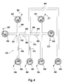
- the microfluidic system 310 shown in FIG. 4 represents a partial section of the Microfluidic system 10 according to FIG. 1 and is otherwise similar to the Microfluidic system 210 shown in FIG. 3 designed channel parts.
- the Microfluidic system 310 comprises a connection channel 401 which is connected at one end to the Reservoir 333 is fluidly connected, in which serving as separation substance buffer 353rd is included.
- the connecting channel 401 opens at the injection site 365 in an injection room. In this injection room, three more channels open, namely, the two side channels 402 and 403 and here as a separation channel serving working channel 370.
- the working channel 370 has at its from the Injection point 365 facing away from a reservoir 335 for receiving the waste 355 on.
- each reservoir 321, 322, 334 and the reservoirs 332, 336, 337 fluidly arranged.
- Each reservoir 321, 322, 332, 333, 334, 335, 336, 337 is in each case contacted with an electrode 371, 372, 382, 383, 384, 385, 386, 397, for input and / or output electrical characteristics, in particular electrical Serve voltage and / or electrical current.
- the samples 341, 342 and 352 and in the reservoir 337 is in this case the Reference liquid 394 was added. It is understood that the reservoir 337 in the generally also usable for receiving a sample liquid.
- microfluidic chips A Big Advantage of Being Open Networks by interconnected fluid-channeled microfluidic systems, In particular, microfluidic chips is that this is a particularly economical Working with a variety of different samples in a small space enable. It is therefore at electrophoretic and / or electroosmotic Separation analyzes usual that parallel to the separation analysis concerning a specific Sample substance, for example, the sample 341, the next operation or the subsequent separation analysis is already prepared so that in a so-called Preinjection phase, the next sample, for example, the sample 352, to an in As close as possible to the injection point 365 arranged transition point 367 "is pulled".
- this channel part is also designed as a working channel 400.
- the reference channel 399 is provided at the end remote from the transition point 367 the reservoir 337 with the reference liquid 394 or another sample is arranged.
- a kind of virtual electrode can be created at the transition point 367. This is achieved by first regulating the electrical current (I 2 ) to zero at the second electrode 397 functioning as a sensor, so that in this way the electrical voltage (U 2 ) at the second electrode 397 is measured or detected can be.
- an arbitrary electrical voltage (U 1 ) is applied to the first electrode 382, which is contacted with the reservoir 352 receiving the sample 352.
- the electrical voltage (U 1 ) at the first electrode 382 is regulated to a voltage value which is increased by a predetermined voltage value of, for example, 200 volts.
- a predetermined voltage value for example, 200 volts.
- that voltage difference is selected as a predetermined voltage value, which has proven useful or necessary in preliminary tests for the movement of the fluid in question or the components contained therein in the intended time.
- the desired voltage difference can be kept essentially constant by means of the regulator according to the invention in accordance with the exemplary embodiment shown in FIG. 2, again by changing the electrical voltage (U 2 ) is measured on the second electrode 397 formed as a measuring electrode and by proceeding according to the steps described above.
- the target current (I 3 -Soll) at the third electrode 386 becomes the sum of the current (I 1 ) measured at the first electrode 382 and a predetermined current (I 4 ) (arrow 404) also calculated as the fourth channel called side channel 402.
- the current intensity (I 3 ) at the third electrode 386 is controlled to the value of the previously calculated desired current intensity (I 3 -Soll), by means of a further, not shown in the figures controller.
- the first electrode 382 also serves as a measuring electrode for measuring the electrical current intensity (I 1 ).
Landscapes
- Health & Medical Sciences (AREA)
- Chemical & Material Sciences (AREA)
- Life Sciences & Earth Sciences (AREA)
- Molecular Biology (AREA)
- Analytical Chemistry (AREA)
- Chemical Kinetics & Catalysis (AREA)
- General Health & Medical Sciences (AREA)
- Pathology (AREA)
- Electrochemistry (AREA)
- Physics & Mathematics (AREA)
- Biochemistry (AREA)
- General Physics & Mathematics (AREA)
- Immunology (AREA)
- Dispersion Chemistry (AREA)
- Hematology (AREA)
- Clinical Laboratory Science (AREA)
- Physical Or Chemical Processes And Apparatus (AREA)
- Automatic Analysis And Handling Materials Therefor (AREA)
Applications Claiming Priority (1)
| Application Number | Priority Date | Filing Date | Title |
|---|---|---|---|
| EP01115587A EP1270073B1 (fr) | 2001-06-28 | 2001-06-28 | Système microfluidique avec régulateur |
Related Parent Applications (1)
| Application Number | Title | Priority Date | Filing Date |
|---|---|---|---|
| EP01115587A Division EP1270073B1 (fr) | 2001-06-28 | 2001-06-28 | Système microfluidique avec régulateur |
Publications (1)
| Publication Number | Publication Date |
|---|---|
| EP1493487A1 true EP1493487A1 (fr) | 2005-01-05 |
Family
ID=8177853
Family Applications (2)
| Application Number | Title | Priority Date | Filing Date |
|---|---|---|---|
| EP01115587A Expired - Lifetime EP1270073B1 (fr) | 2001-06-28 | 2001-06-28 | Système microfluidique avec régulateur |
| EP04103981A Withdrawn EP1493487A1 (fr) | 2001-06-28 | 2001-06-28 | Système microfluidique avec régulation du courant ESI résiduel |
Family Applications Before (1)
| Application Number | Title | Priority Date | Filing Date |
|---|---|---|---|
| EP01115587A Expired - Lifetime EP1270073B1 (fr) | 2001-06-28 | 2001-06-28 | Système microfluidique avec régulateur |
Country Status (3)
| Country | Link |
|---|---|
| US (1) | US7243670B2 (fr) |
| EP (2) | EP1270073B1 (fr) |
| DE (1) | DE50105368D1 (fr) |
Cited By (4)
| Publication number | Priority date | Publication date | Assignee | Title |
|---|---|---|---|---|
| DE102007018752A1 (de) * | 2007-04-20 | 2008-10-30 | Fraunhofer-Gesellschaft zur Förderung der angewandten Forschung e.V. | Vorrichtung und Verfahren zum geregelten Transport Mikrofluidischer Proben |
| CN103447103A (zh) * | 2013-08-27 | 2013-12-18 | 苏州文曲生物微系统有限公司 | 一种微电极芯片的封装结构 |
| WO2017157304A1 (fr) * | 2016-03-16 | 2017-09-21 | 清华大学深圳研究生院 | Puce de source d'ions microfluidique et procédé de préparation associé |
| WO2019006977A1 (fr) * | 2017-07-03 | 2019-01-10 | 南京岚煜生物科技有限公司 | Puce microfluidique à flux multiples basée sur une commande active sur un écoulement de liquide |
Families Citing this family (70)
| Publication number | Priority date | Publication date | Assignee | Title |
|---|---|---|---|---|
| US6803568B2 (en) * | 2001-09-19 | 2004-10-12 | Predicant Biosciences, Inc. | Multi-channel microfluidic chip for electrospray ionization |
| US7105810B2 (en) * | 2001-12-21 | 2006-09-12 | Cornell Research Foundation, Inc. | Electrospray emitter for microfluidic channel |
| EP1560642A4 (fr) * | 2002-10-09 | 2006-05-03 | Univ Illinois | Systemes et composants microfluidiques |
| SE0300454D0 (sv) * | 2003-02-19 | 2003-02-19 | Aamic Ab | Nozzles for electrospray ionization and methods of fabricating them |
| US7007710B2 (en) * | 2003-04-21 | 2006-03-07 | Predicant Biosciences, Inc. | Microfluidic devices and methods |
| JPWO2005024436A1 (ja) * | 2003-09-02 | 2007-11-08 | 日本電気株式会社 | カスタマイズ可能なチップおよびその製造方法 |
| US7537807B2 (en) * | 2003-09-26 | 2009-05-26 | Cornell University | Scanned source oriented nanofiber formation |
| CN100429511C (zh) * | 2004-04-09 | 2008-10-29 | 南京大学 | 一种集成于芯片毛细管电泳的电化学检测方法 |
| US20060022130A1 (en) * | 2004-07-29 | 2006-02-02 | Predicant Biosciences, Inc., A Delaware Corporation | Microfluidic devices and methods with integrated electrical contact |
| US7291824B2 (en) * | 2005-12-22 | 2007-11-06 | Palo Alto Research Center Incorporated | Photosensing throughout energy range and in subranges |
| US7522786B2 (en) * | 2005-12-22 | 2009-04-21 | Palo Alto Research Center Incorporated | Transmitting light with photon energy information |
| US20060060769A1 (en) * | 2004-09-21 | 2006-03-23 | Predicant Biosciences, Inc. | Electrospray apparatus with an integrated electrode |
| US7591883B2 (en) * | 2004-09-27 | 2009-09-22 | Cornell Research Foundation, Inc. | Microfiber supported nanofiber membrane |
| DE102004051394B4 (de) * | 2004-10-21 | 2006-08-17 | Advalytix Ag | Verfahren zur Bewegung von kleinen Flüssigkeitsmengen in Mikrokanälen und Mikrokanalsystem |
| US20070012891A1 (en) * | 2004-12-08 | 2007-01-18 | George Maltezos | Prototyping methods and devices for microfluidic components |
| US8695355B2 (en) | 2004-12-08 | 2014-04-15 | California Institute Of Technology | Thermal management techniques, apparatus and methods for use in microfluidic devices |
| DE102005000835B3 (de) * | 2005-01-05 | 2006-09-07 | Advalytix Ag | Verfahren und Vorrichtung zur Dosierung kleiner Flüssigkeitsmengen |
| EP1833598B1 (fr) | 2005-01-05 | 2008-10-08 | Olympus Life Science Research Europa GmbH | Procede et dispositif de dosage et de melange de petites quantites de liquide |
| US7358476B2 (en) | 2005-12-22 | 2008-04-15 | Palo Alto Research Center Incorporated | Sensing photons from objects in channels |
| US8437582B2 (en) * | 2005-12-22 | 2013-05-07 | Palo Alto Research Center Incorporated | Transmitting light with lateral variation |
| US7433552B2 (en) * | 2005-12-22 | 2008-10-07 | Palo Alto Research Center Incorporated | Obtaining analyte information |
| US7547904B2 (en) * | 2005-12-22 | 2009-06-16 | Palo Alto Research Center Incorporated | Sensing photon energies emanating from channels or moving objects |
| US7386199B2 (en) * | 2005-12-22 | 2008-06-10 | Palo Alto Research Center Incorporated | Providing light to channels or portions |
| US7420677B2 (en) * | 2005-12-22 | 2008-09-02 | Palo Alto Research Center Incorporated | Sensing photon energies of optical signals |
| US7315667B2 (en) * | 2005-12-22 | 2008-01-01 | Palo Alto Research Center Incorporated | Propagating light to be sensed |
| US8137626B2 (en) * | 2006-05-19 | 2012-03-20 | California Institute Of Technology | Fluorescence detector, filter device and related methods |
| WO2008024138A1 (fr) * | 2006-08-23 | 2008-02-28 | Georgia Tech Research Corporation | Systèmes détecteurs assistés par fluide pour une détection rapide de substances chimiques et biologiques |
| WO2008036614A1 (fr) * | 2006-09-18 | 2008-03-27 | California Institute Of Technology | Appareil de détection de molécules cibles et procédés associés |
| US7814928B2 (en) * | 2006-10-10 | 2010-10-19 | California Institute Of Technology | Microfluidic devices and related methods and systems |
| CA2580589C (fr) | 2006-12-19 | 2016-08-09 | Fio Corporation | Systeme de detection microfluidique |
| WO2008091568A2 (fr) | 2007-01-23 | 2008-07-31 | Dtherapeutics, Llc | Applications des lois dimensionnelles des arborescences |
| US9591994B2 (en) | 2007-01-23 | 2017-03-14 | Dtherapeutics, Llc | Systems and methods to obtain a myocardial mass index indicative of an at-risk myocardial region |
| US9164037B2 (en) | 2007-01-26 | 2015-10-20 | Palo Alto Research Center Incorporated | Method and system for evaluation of signals received from spatially modulated excitation and emission to accurately determine particle positions and distances |
| US8821799B2 (en) * | 2007-01-26 | 2014-09-02 | Palo Alto Research Center Incorporated | Method and system implementing spatially modulated excitation or emission for particle characterization with enhanced sensitivity |
| US7936463B2 (en) * | 2007-02-05 | 2011-05-03 | Palo Alto Research Center Incorporated | Containing analyte in optical cavity structures |
| US7633629B2 (en) | 2007-02-05 | 2009-12-15 | Palo Alto Research Center Incorporated | Tuning optical cavities |
| US7554673B2 (en) * | 2007-02-05 | 2009-06-30 | Palo Alto Research Center Incorporated | Obtaining information about analytes using optical cavity output light |
| US8360321B2 (en) | 2007-04-02 | 2013-01-29 | Fio Corporation | System and method of deconvolving multiplexed fluorescence spectral signals generated by quantum dot optical coding technology |
| JP2010530912A (ja) | 2007-06-22 | 2010-09-16 | フィオ コーポレイション | 量子ドットをドープしたポリマーマイクロビーズの製造システム及び方法 |
| WO2009006739A1 (fr) | 2007-07-09 | 2009-01-15 | Fio Corporation | Systèmes et procédés pour améliorer la détection de fluorescence de molécules cibles dans un échantillon de test |
| GB2453534A (en) * | 2007-10-08 | 2009-04-15 | Shaw Stewart P D | Method for adding solutions to droplets in a microfluidic environment using electric potentials or ultrasound |
| CN101861203B (zh) | 2007-10-12 | 2014-01-22 | Fio公司 | 用于形成浓缩体积的微珠的流动聚焦方法和系统以及形成的微珠 |
| US8320983B2 (en) | 2007-12-17 | 2012-11-27 | Palo Alto Research Center Incorporated | Controlling transfer of objects affecting optical characteristics |
| US8373860B2 (en) | 2008-02-01 | 2013-02-12 | Palo Alto Research Center Incorporated | Transmitting/reflecting emanating light with time variation |
| US8629981B2 (en) | 2008-02-01 | 2014-01-14 | Palo Alto Research Center Incorporated | Analyzers with time variation based on color-coded spatial modulation |
| NL2001431C2 (nl) | 2008-04-02 | 2009-10-05 | Univ Delft Tech | Werkwijze voor het scheiden van een afvalstroom. |
| US20110137596A1 (en) * | 2008-04-30 | 2011-06-09 | The Board Of Regents Of The University Of Texas System | Quality control method and micro/nano-channeled devices |
| US9792809B2 (en) | 2008-06-25 | 2017-10-17 | Fio Corporation | Bio-threat alert system |
| BRPI0917839A2 (pt) | 2008-08-29 | 2015-11-24 | Fio Corp | dispositivo de teste de diagnóstico portátil de uso único, e um sistema associado e método para teste de amostras de teste ambientais e biológicas |
| CN104374932A (zh) | 2009-01-13 | 2015-02-25 | Fio公司 | 与电子设备和快速诊断测试中的测试盒结合使用的手持诊断测试设备 |
| CA2764678C (fr) | 2009-06-04 | 2017-12-12 | Lockheed Martin Corporation | Puce microfluidique a echantillons multiples pour l'analyse d'adn |
| ES2425338T3 (es) | 2010-07-28 | 2013-10-14 | Inashco R&D B.V. | Aparato de separación |
| AU2011315951B2 (en) | 2010-10-15 | 2015-03-19 | Lockheed Martin Corporation | Micro fluidic optic design |
| WO2012094325A2 (fr) * | 2011-01-03 | 2012-07-12 | Cytonome/St. Llc | Procédé et appareil de surveillance et d'optimisation de tri de particules |
| NL2006306C2 (en) * | 2011-02-28 | 2012-08-29 | Inashco R & D B V | Eddy current seperation apparatus, separation module, separation method and method for adjusting an eddy current separation apparatus. |
| DE102011076051A1 (de) | 2011-05-18 | 2012-11-22 | Siemens Aktiengesellschaft | Magnetophoretische Analytselektion und -anreicherung |
| US8723140B2 (en) | 2011-08-09 | 2014-05-13 | Palo Alto Research Center Incorporated | Particle analyzer with spatial modulation and long lifetime bioprobes |
| US9029800B2 (en) | 2011-08-09 | 2015-05-12 | Palo Alto Research Center Incorporated | Compact analyzer with spatial modulation and multiple intensity modulated excitation sources |
| US9322054B2 (en) | 2012-02-22 | 2016-04-26 | Lockheed Martin Corporation | Microfluidic cartridge |
| US9222874B2 (en) * | 2012-06-27 | 2015-12-29 | The United States Of America As Represented By The Secretary Of The Army | Systems and methods for individually trapping particles from air and measuring the optical spectra or other properties of individual trapped particles |
| CN102764676B (zh) * | 2012-07-23 | 2014-08-06 | 西安交通大学 | 非接触式光驱动-双极电极的微流控芯片 |
| CN102950037B (zh) * | 2012-11-16 | 2015-05-20 | 北京工业大学 | 一种金属微流控芯片上的微流体驱动方法 |
| CN106153701A (zh) * | 2015-04-23 | 2016-11-23 | 宁波大学 | 检测多种亚型猪流感用双驱动耦合模式微流控芯片装置 |
| EP3957986B1 (fr) | 2015-11-30 | 2024-09-18 | Intabio, Llc | Procédés de caractérisation d'échantillons |
| WO2019148198A1 (fr) * | 2018-01-29 | 2019-08-01 | Intabio, Inc. | Dispositifs, procédés et kits de caractérisation d'échantillon |
| CN112534549B (zh) * | 2018-05-31 | 2025-03-21 | 因塔生物有限责任公司 | 用于微流体系统与质谱联用的软件 |
| US12296509B2 (en) * | 2018-08-09 | 2025-05-13 | Hummingbird Nano, Inc. | Microfluidic device and method of manufacture |
| US12594557B2 (en) | 2019-08-12 | 2026-04-07 | Intabio, Llc | Isoelectric focusing devices and fixtures |
| US11285484B2 (en) | 2019-08-12 | 2022-03-29 | Intabio, Llc | Multichannel isoelectric focusing devices and high voltage power supplies |
| CN120054667B (zh) * | 2025-02-20 | 2025-12-05 | 北京博晖创新生物技术集团股份有限公司 | 压力式微流控芯片及其检测设备 |
Citations (4)
| Publication number | Priority date | Publication date | Assignee | Title |
|---|---|---|---|---|
| WO2000022409A2 (fr) * | 1998-10-09 | 2000-04-20 | University Of Alberta | Dispositifs microfluidiques connectes a des capillaires en minimisant le volume inutilise |
| DE19947496A1 (de) * | 1999-10-01 | 2001-04-05 | Hewlett Packard Co | Sprühspitze für einen mikrofluidischen Labor-Mikrochip |
| US6221226B1 (en) * | 1997-07-15 | 2001-04-24 | Caliper Technologies Corp. | Methods and systems for monitoring and controlling fluid flow rates in microfluidic systems |
| DE19947495A1 (de) * | 1999-10-01 | 2001-05-17 | Hewlett Packard Co | Mikrostrukturankopplung für einen Labor-Mikrochip |
Family Cites Families (11)
| Publication number | Priority date | Publication date | Assignee | Title |
|---|---|---|---|---|
| US4908112A (en) * | 1988-06-16 | 1990-03-13 | E. I. Du Pont De Nemours & Co. | Silicon semiconductor wafer for analyzing micronic biological samples |
| DE59410283D1 (de) * | 1993-11-11 | 2003-06-18 | Aclara Biosciences Inc | Vorrichtung und Verfahren zur elektrophoretischen Trennung von fluiden Substanzgemischen |
| US6001229A (en) * | 1994-08-01 | 1999-12-14 | Lockheed Martin Energy Systems, Inc. | Apparatus and method for performing microfluidic manipulations for chemical analysis |
| US5885470A (en) * | 1997-04-14 | 1999-03-23 | Caliper Technologies Corporation | Controlled fluid transport in microfabricated polymeric substrates |
| AU726987B2 (en) * | 1996-06-28 | 2000-11-30 | Caliper Life Sciences, Inc. | Electropipettor and compensation means for electrophoretic bias |
| US5800690A (en) * | 1996-07-03 | 1998-09-01 | Caliper Technologies Corporation | Variable control of electroosmotic and/or electrophoretic forces within a fluid-containing structure via electrical forces |
| US6110343A (en) * | 1996-10-04 | 2000-08-29 | Lockheed Martin Energy Research Corporation | Material transport method and apparatus |
| US6042208A (en) * | 1997-06-03 | 2000-03-28 | Eastman Kodak Company | Image producing apparatus for microfluidic printing |
| US6220747B1 (en) * | 1997-08-14 | 2001-04-24 | Michael Gosselin | Proportional pump system for viscous fluids |
| US6167910B1 (en) * | 1998-01-20 | 2001-01-02 | Caliper Technologies Corp. | Multi-layer microfluidic devices |
| GB9929069D0 (en) * | 1999-12-08 | 2000-02-02 | Imperial College | Potentiometric sensor |
-
2001
- 2001-06-28 EP EP01115587A patent/EP1270073B1/fr not_active Expired - Lifetime
- 2001-06-28 DE DE50105368T patent/DE50105368D1/de not_active Expired - Fee Related
- 2001-06-28 EP EP04103981A patent/EP1493487A1/fr not_active Withdrawn
-
2002
- 2002-06-24 US US10/178,569 patent/US7243670B2/en not_active Expired - Lifetime
Patent Citations (4)
| Publication number | Priority date | Publication date | Assignee | Title |
|---|---|---|---|---|
| US6221226B1 (en) * | 1997-07-15 | 2001-04-24 | Caliper Technologies Corp. | Methods and systems for monitoring and controlling fluid flow rates in microfluidic systems |
| WO2000022409A2 (fr) * | 1998-10-09 | 2000-04-20 | University Of Alberta | Dispositifs microfluidiques connectes a des capillaires en minimisant le volume inutilise |
| DE19947496A1 (de) * | 1999-10-01 | 2001-04-05 | Hewlett Packard Co | Sprühspitze für einen mikrofluidischen Labor-Mikrochip |
| DE19947495A1 (de) * | 1999-10-01 | 2001-05-17 | Hewlett Packard Co | Mikrostrukturankopplung für einen Labor-Mikrochip |
Non-Patent Citations (1)
| Title |
|---|
| RAMSEY R S ET AL: "GENERATING ELECTROSPRAY FROM MICROCHIP DEVICES USING ELECTROOSMOTICPUMPING", ANALYTICAL CHEMISTRY, AMERICAN CHEMICAL SOCIETY. COLUMBUS, US, vol. 69, no. 6, 15 March 1997 (1997-03-15), pages 1174 - 1178, XP000686381, ISSN: 0003-2700 * |
Cited By (6)
| Publication number | Priority date | Publication date | Assignee | Title |
|---|---|---|---|---|
| DE102007018752A1 (de) * | 2007-04-20 | 2008-10-30 | Fraunhofer-Gesellschaft zur Förderung der angewandten Forschung e.V. | Vorrichtung und Verfahren zum geregelten Transport Mikrofluidischer Proben |
| DE102007018752B4 (de) * | 2007-04-20 | 2011-09-22 | Fraunhofer-Gesellschaft zur Förderung der angewandten Forschung e.V. | Vorrichtung und Verfahren zum geregelten Transport mikrofluidischer Proben |
| CN103447103A (zh) * | 2013-08-27 | 2013-12-18 | 苏州文曲生物微系统有限公司 | 一种微电极芯片的封装结构 |
| WO2017157304A1 (fr) * | 2016-03-16 | 2017-09-21 | 清华大学深圳研究生院 | Puce de source d'ions microfluidique et procédé de préparation associé |
| WO2019006977A1 (fr) * | 2017-07-03 | 2019-01-10 | 南京岚煜生物科技有限公司 | Puce microfluidique à flux multiples basée sur une commande active sur un écoulement de liquide |
| US10761092B2 (en) | 2017-07-03 | 2020-09-01 | Lansion Biotechnology Co., Ltd. | Multi-flux micro-fluidic chip based on active fluid flow control |
Also Published As
| Publication number | Publication date |
|---|---|
| US20030000835A1 (en) | 2003-01-02 |
| EP1270073A1 (fr) | 2003-01-02 |
| US7243670B2 (en) | 2007-07-17 |
| DE50105368D1 (de) | 2005-03-24 |
| EP1270073B1 (fr) | 2005-02-16 |
Similar Documents
| Publication | Publication Date | Title |
|---|---|---|
| EP1270073B1 (fr) | Système microfluidique avec régulateur | |
| DE69530669T2 (de) | Vermischen von Flüssigkeiten mittels Elektroosmose | |
| DE69120058T2 (de) | Verbesserte kapillarzonenelektrophorese und geräte zur durchführung des verfahrens | |
| DE19847952C2 (de) | Fluidstromschalter | |
| DE2363195C3 (fr) | ||
| DE69806499T2 (de) | Serpentinenförmiger elektroforetischer kanal mit selbstkorrigierenden kurven | |
| DE4422801A1 (de) | Elektroosmotische Flußsteuerung unter Verwendung von Gegendruck bei der Kapillarelektrophorese | |
| DE69124556T2 (de) | Verfahren und Vorrichtung zur Einführung mindestens eines Flüssigkeitsvolumens in eine Röhre, insbesondere für kapillare Elektrophoresesysteme und Verfahren und Vorrichtung zur Trennung und/oder Analyse eines fluiden Materials | |
| DE2363195A1 (de) | Verfahren zur fixierung einer probe in einer bestimmten position bei der gegenflussisotachophorese | |
| EP1979738B1 (fr) | Dispositif de réalisation de flux de liquides et/ou de courants de particules, son procédé de fabrication et de fonctionnement et son utilisation | |
| DE10005735A1 (de) | Verfahren und Vorrichtung zur Abführung suspendierter Mikropartikel aus einem fluidischen Mikrosystem | |
| DE10063096C1 (de) | Elektrophoresevorrichtung, Elektrophoreseverfahren unter Verwendung einer Elektrophoresevorrichtung und Verwendung der Elektrophoresevorrichtung | |
| DE60026363T2 (de) | Elektroforetische trennungsvorrichtung und zugehöriges verwendungsverfahren | |
| DE69308806T2 (de) | Verfahren und Vorrichtung zum Injizieren von Flüssigkeit in ein Kapillarrohr | |
| DE19826020C2 (de) | Vorrichtung und Verfahren zur miniaturisierten, hochparallelen elektrophoretischen Trennung | |
| DE4314755C2 (de) | Kapillarelektrophoretisches Trennverfahren sowie Vorrichtung zur Durchführung von chemischen oder biochemischen Analysen | |
| DE4105107A1 (de) | Kontinuierliches durchfluss-analysesystem, insbesondere fliess-injektions-analysesystem und verfahren zum betrieb eines derartigen analysesystems | |
| DE4244825C2 (de) | Verfahren zur Durchführung einer kapillarelektrophoretischen Bestimmung | |
| EP0928418B1 (fr) | Procede et dispositif pour la separation isoelectrique de particules | |
| DE202014101518U1 (de) | Vorrichtung für die Feldflussfraktionierung | |
| DE102006035072A1 (de) | Vorrichtung und Verfahren zum Erfassen von Partikeln mit Pipette und Nanopore | |
| DE102014205991B4 (de) | Vorrichtung für die Feldflussfraktionierung und Verfahren zur Probentrennung mittels Feldflussfraktionierung | |
| DE102020120425A1 (de) | Verfahren und fluidisches Mikrosystem zur dielektrophoretischen Manipulierung von suspendierten Partikeln | |
| DE19927534B4 (de) | Vorrichtung zur Probenaufgabe | |
| DE4232781C1 (de) | Verfahren zum Abtrennen einzelner Bestandteile eines Stoffgemisches |
Legal Events
| Date | Code | Title | Description |
|---|---|---|---|
| PUAI | Public reference made under article 153(3) epc to a published international application that has entered the european phase |
Free format text: ORIGINAL CODE: 0009012 |
|
| AC | Divisional application: reference to earlier application |
Ref document number: 1270073 Country of ref document: EP Kind code of ref document: P |
|
| AK | Designated contracting states |
Kind code of ref document: A1 Designated state(s): CH DE FR GB LI |
|
| 17P | Request for examination filed |
Effective date: 20050705 |
|
| AKX | Designation fees paid |
Designated state(s): DE FR GB |
|
| 17Q | First examination report despatched |
Effective date: 20060502 |
|
| RAP1 | Party data changed (applicant data changed or rights of an application transferred) |
Owner name: AGILENT TECHNOLOGIES, INC. |
|
| STAA | Information on the status of an ep patent application or granted ep patent |
Free format text: STATUS: THE APPLICATION IS DEEMED TO BE WITHDRAWN |
|
| 18D | Application deemed to be withdrawn |
Effective date: 20080103 |