EP1493529A1 - Montagemaschine mit einem Montagewerkzeug tragendem Revolver - Google Patents
Montagemaschine mit einem Montagewerkzeug tragendem Revolver Download PDFInfo
- Publication number
- EP1493529A1 EP1493529A1 EP04360059A EP04360059A EP1493529A1 EP 1493529 A1 EP1493529 A1 EP 1493529A1 EP 04360059 A EP04360059 A EP 04360059A EP 04360059 A EP04360059 A EP 04360059A EP 1493529 A1 EP1493529 A1 EP 1493529A1
- Authority
- EP
- European Patent Office
- Prior art keywords
- assembly
- turret
- machine according
- axis
- carriage
- Prior art date
- Legal status (The legal status is an assumption and is not a legal conclusion. Google has not performed a legal analysis and makes no representation as to the accuracy of the status listed.)
- Granted
Links
Images



Classifications
-
- B—PERFORMING OPERATIONS; TRANSPORTING
- B23—MACHINE TOOLS; METAL-WORKING NOT OTHERWISE PROVIDED FOR
- B23P—METAL-WORKING NOT OTHERWISE PROVIDED FOR; COMBINED OPERATIONS; UNIVERSAL MACHINE TOOLS
- B23P19/00—Machines for simply fitting together or separating metal parts or objects, or metal and non-metal parts, whether or not involving some deformation; Tools or devices therefor so far as not provided for in other classes
-
- B—PERFORMING OPERATIONS; TRANSPORTING
- B23—MACHINE TOOLS; METAL-WORKING NOT OTHERWISE PROVIDED FOR
- B23P—METAL-WORKING NOT OTHERWISE PROVIDED FOR; COMBINED OPERATIONS; UNIVERSAL MACHINE TOOLS
- B23P19/00—Machines for simply fitting together or separating metal parts or objects, or metal and non-metal parts, whether or not involving some deformation; Tools or devices therefor so far as not provided for in other classes
- B23P19/02—Machines for simply fitting together or separating metal parts or objects, or metal and non-metal parts, whether or not involving some deformation; Tools or devices therefor so far as not provided for in other classes for connecting objects by press fit or for detaching same
-
- B—PERFORMING OPERATIONS; TRANSPORTING
- B23—MACHINE TOOLS; METAL-WORKING NOT OTHERWISE PROVIDED FOR
- B23P—METAL-WORKING NOT OTHERWISE PROVIDED FOR; COMBINED OPERATIONS; UNIVERSAL MACHINE TOOLS
- B23P21/00—Machines for assembling a multiplicity of different parts to compose units, with or without preceding or subsequent working of such parts, e.g. with program control
Definitions
- a machine fitting of this type exists and includes a turret carrying several tools the axis of rotation of the turret and the axis of the tools being all parallel to the axis of fitting.
- This provision generates disadvantages since the waiting tools interfere with the workpieces.
- each tool holder is mounted on a carriage to clear the tools waiting in relation to the tool at work. The stroke of the tool in work is therefore bigger and the machine higher.
- this machine also includes a counter-turret arranged under a reference table.
- the invention relates to an assembly machine of the kind indicated in preamble, characterized in that it comprises a turret arranged to carry a plurality of assembly tools, said turret being rotatably mounted on said carriage about an axis of rotation not parallel to said assembly axis and arranged in order to present a single assembly tool in working position, the others assembly tools being in standby position on separate axes of said axis assembly, said turret being disposed on said carriage so that the effort of thrust generated by the actuating means is transmitted to said assembly tool in the working position by said carriage without being taken up by said turret.
- the axis of rotation of the turret and the axis of assembly brought back in the same plane are secants of an angle ⁇ which may be between 30 ° and 60 ° and preferably equal to 45 °.
- the assembly machine comprises means for rotating the turret provided with at least one engine coupled to an engine pinion meshing a pinion receiver coupled to the outer body of the turret.
- the receiving pinion is advantageously formed by a toothed outer ring secured to the rolling means.
- the assembly tools are preferably mounted on the turret by means of removable mounting.
- the actuating means comprise at least one less a motor coupled to a screw meshing a nut integral with the movable carriage.
- they may comprise a manipulator arranged for present the second piece to be assembled in the assembly axis or a conveyor of an assembly line.
- the assembly machine comprises at least a counter-support disposed in the assembly axis opposite the assembly tool in working position and arranged to oppose said thrust force.
- the counter-support can be fixed in translation relative to the frame while the means positioning devices can be mobile in translation with respect to this frame and move with the moving cart.
- the opposite is also possible according to applications, namely that the positioning means can be fixed in translation relative to the frame and the counter-support can be movable in translation by compared to this frame.
- the positioning means and the counter-support can be integrated.
- the actuating means may also comprise at least one sensor of force disposed between the carriage and the assembly tool in the working position for control the thrust force.
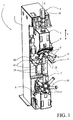
- the assembly machine 1 is intended to assemble at least two mechanical parts, for example by fitting, interlocking, snapping, etc.
- This assembly machine 1 comprises a frame 2 on which slides a carriage 3 along two guide rails 21, which may be ball rails for example.
- This carriage 3 is mobile in translation in a direction materialized by a double arrow T substantially parallel to the assembly axis A parts to assemble. It is provided with at least one assembly tool 4 whose axis, in working position, coincides with the axis assembly A carrying at least a first part to be assembled.
- This machine assembly 1 also comprises actuating means 5 coupled to the carriage 3 to drive it in translation.
- the actuating means 5 comprise, in a manner known, an electric servomotor 50, a gear 51 which may be optional, a mechanical coupling 52, a bearing 53 secured to the frame 2 and formed for example an axial stop with rollers, and a screw 54 meshing with a nut 55 integral with the carriage 3.
- the screw / nut assembly is of the ball or roller type or any another suitable type.
- the encoder of the electric servomotor 50 makes it possible to control the 3.
- these actuating means 5 can be constituted by other equipment, such as other types of electric motors, a hydraulic cylinder, etc.
- the assembly machine 1 particularly includes a turret 8 arranged to carry several assembly tools 4, 4 ', for example six as shown.
- This turret 8 is rotatably mounted on the carriage 3 around an axis of rotation R not parallel to the assembly axis A and disposed of to present a single assembly tool 4 in working position, the other tools 4 'assembly being in waiting position on separate axes of the assembly axis A.
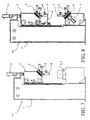
- the rotation axis R of the turret 8 and the assembly axis A brought back into the same plane are secants of an angle ⁇ between 30 ° and 60 ° and for example equal to 45 ° as in the figures.
- This turret 8 is shown in more detail in FIGS. 3 to 5. It comprises a inner hollow body 80 integral with the carriage 3 and an outer hollow hollow body 81 in rotation relative to the inner body 80 by means of a roller bearing 82 tapered for example or any other suitable rolling means. She is associated to rotating drive means 9 provided with a coupled electric motor 90 to a drive pinion 91 meshing with a pinion receiver 92 secured to the turret 8.
- the outer body 81 has a substantially frustoconical portion in which there are provided through slots 83 for receiving each a tool assembly 4, 4 '.
- These housings 83 are arranged on the same circle whose center is coincident with the axis of rotation R, so that the axes of the assembly tools 4, 4 'intersect the axis of rotation R at the same point P.
- the inner body 80 forms in view of the assembly tools 4, 4 'an axial stop 84 limiting the stroke of the part mobile tools in the retracted position as explained below.
- the inner body 80 of the turret 8 is hollow to allow the transmission of the thrust force generated by the actuating means 5 to the assembly tool 4 in position without being taken up by the turret 8, this transmission being ensured, in the example shown, by a transmission part 56 as explained below.
- the front face of the turret 8 has a central opening 85 through arranged between slots 83 for the passage of possible technical conduits allowing to supply the assembly tools 4, 4 'with water, oil, air, electricity, etc. by example. When not in use, this opening 85 is closed by a cover 86.
- FIG. tubular body 40 intended to be fixed on the turret 8 by fixing means of the machine-tool type, that is to say fast, removable, self centered, without adjustment and interview.
- these means are constituted by screws of fixing 41 (FIG 3, 4) passing through orifices 42 formed in a flange 43.
- All another detachable fastening means may be provided, for example, fittings fast, bayonet systems, etc.
- the assembly tool 4, 4 ' has a sheath 44 slidably mounted in the body 40 and through it through.
- This sheath 44 has an inner end 45 inside the turret 8 arranged for receive the thrust force P and an outer end 46 outside the turret 8 arranged to receive a tool head (not shown) adapted to the first piece to to assemble.
- the outer end 46 consists of a disc tip nested or rendered secured to the sheath 44 and covering the corresponding end of the body 40. has a set of holes 46 'threaded or not to receive the organs of attachment of the tool head.
- the inner end 45 has a nested disc end or made integral with an intermediate piece 47 itself fitted or rendered integral with the sleeve 44.
- a return member 48 is disposed between the body 40 and the sleeve 44 to urge it into the out position represented by the arrow S.
- This transmission part 56 consists of a solid tube provided with one of its ends of a sole 56 'intended to be fixed on the carriage 3 and at the other end a disc end 56 "intended to bear flat against the inner end 45 of the assembly tool 4 in working position.
- This transmission part 56 can be complemented by a force sensor 57 able to control the thrust force P and detect the threshold of the counter-thrust indicating that the assembly is carried out.
- Other types of sensor may be provided according to the controls to be performed.
- the assembly machine 1 comprises, with reference to FIGS. 1 and 2, positioning means 6 arranged to present the second part to be assembled in the assembly axis A, or all at less in a collinear axis, the self-centering on the assembly axis A being ensured at both by the chamfers provided on the parts to be assembled and by the compliance radial assembly tool 4.
- positioning means 6 arranged to present the second part to be assembled in the assembly axis A, or all at less in a collinear axis, the self-centering on the assembly axis A being ensured at both by the chamfers provided on the parts to be assembled and by the compliance radial assembly tool 4.
- These positioning means 6 comprise a reference table 60 having at least one flat surface 61 perpendicular to the assembly axis A, this flat surface 61 may be its upper face and / or its lower side.
- the reference table 60 can be fixedly mounted on the frame 2 or mobile in translation along the double arrow T along the guide rails 21 of the frame 2 as explained below.
- the second piece to be assembled can be presented directly against the flat surface 61 if it comprises a reference surface substantially flat or via an adapter (not shown). This second piece with or without an adapter is usually handled by a robot or any other similar equipment capable of removing it from a shop, pallet or assembly line and maintain it during the assembly operation.
- the reference table 60 is mounted mobile in translation relative to the 2 and is driven in the direction of the counter-turret 10 by the carriage 3 during a assembly operation.
- This construction ensures mechanical rigidity counter-support 7 and simultaneously maintaining in reference the second piece to to assemble.
- this assembly machine can be managed, controlled, controlled, automatically fed by an IT central control unit operating cycles and manipulators of the parts to be assembled, tools and counter-tools depending on the parts to be assembled and the operations to be performed.
Landscapes
- Engineering & Computer Science (AREA)
- Mechanical Engineering (AREA)
- Cutting Tools, Boring Holders, And Turrets (AREA)
- Turning (AREA)
- Automatic Tool Replacement In Machine Tools (AREA)
- Automobile Manufacture Line, Endless Track Vehicle, Trailer (AREA)
- Chain Conveyers (AREA)
- Automatic Assembly (AREA)
- Auxiliary Devices For And Details Of Packaging Control (AREA)
- Devices For Conveying Motion By Means Of Endless Flexible Members (AREA)
Applications Claiming Priority (2)
| Application Number | Priority Date | Filing Date | Title |
|---|---|---|---|
| FR0308007A FR2856945B1 (fr) | 2003-07-02 | 2003-07-02 | Machine d'assemblage |
| FR0308007 | 2003-07-02 |
Publications (2)
| Publication Number | Publication Date |
|---|---|
| EP1493529A1 true EP1493529A1 (de) | 2005-01-05 |
| EP1493529B1 EP1493529B1 (de) | 2007-01-03 |
Family
ID=33427665
Family Applications (1)
| Application Number | Title | Priority Date | Filing Date |
|---|---|---|---|
| EP04360059A Expired - Lifetime EP1493529B1 (de) | 2003-07-02 | 2004-06-22 | Montagemaschine mit einem Montagewerkzeuge tragenden Revolver |
Country Status (5)
| Country | Link |
|---|---|
| EP (1) | EP1493529B1 (de) |
| AT (1) | ATE350192T1 (de) |
| DE (1) | DE602004004001T2 (de) |
| ES (1) | ES2279323T3 (de) |
| FR (1) | FR2856945B1 (de) |
Cited By (10)
| Publication number | Priority date | Publication date | Assignee | Title |
|---|---|---|---|---|
| EP1695790A3 (de) * | 2005-02-23 | 2010-01-20 | CLAAS Fertigungstechnik GmbH | Montageautomation |
| WO2014170057A1 (de) * | 2013-04-16 | 2014-10-23 | Robert Bosch Gmbh | Montagezentrum und verwendung einer verfahreinheit in einem montagezentrum |
| EP2664412A3 (de) * | 2012-05-18 | 2015-03-04 | KUKA Systems GmbH | Montageeinrichtung und Montagezelle |
| EP3072630A1 (de) * | 2015-03-26 | 2016-09-28 | Gaindu, S.L. | Zelle für das Einsetzen von Bauelementen in Werkstücke |
| EP3093101A1 (de) * | 2015-05-12 | 2016-11-16 | ThyssenKrupp System Engineering GmbH | Wechselanordnung zur aufnahme einer applikationsvorrichtung zum einsatz in einer montagelinie für kraftfahrzeuge |
| CN109262229A (zh) * | 2018-11-23 | 2019-01-25 | 珠海格力智能装备有限公司 | 装配装置 |
| CN112296689A (zh) * | 2020-11-25 | 2021-02-02 | 苏州协同创新智能制造装备有限公司 | 一种名片夹自动组装线 |
| CN112872756A (zh) * | 2021-01-14 | 2021-06-01 | 龙铁纵横(北京)轨道交通科技股份有限公司 | 一种齿轮箱自动化智能装配系统及方法 |
| CN112936146A (zh) * | 2021-02-03 | 2021-06-11 | 内蒙古工业大学 | 一种反向式行星滚柱丝杠副的一体化装配夹具 |
| CN119501545A (zh) * | 2024-12-05 | 2025-02-25 | 佛山朗昊智能科技有限公司 | 一种膨胀螺丝组装机 |
Families Citing this family (1)
| Publication number | Priority date | Publication date | Assignee | Title |
|---|---|---|---|---|
| CN104384925B (zh) * | 2014-10-10 | 2016-08-17 | 兰州空间技术物理研究所 | 磁选态铯束管选态磁铁组件装配系统及装配检验方法 |
Citations (3)
| Publication number | Priority date | Publication date | Assignee | Title |
|---|---|---|---|---|
| FR2631872A1 (fr) * | 1988-05-25 | 1989-12-01 | Somex Sa | Tete revolver pour machine-outil |
| US5509192A (en) * | 1993-03-30 | 1996-04-23 | Ando Electric Co., Ltd. | Apparatus for press-fitting connectors into printed boards |
| JPH11151623A (ja) * | 1997-11-19 | 1999-06-08 | Sadamichi Kumada | グロメット押出装置及びパレット支持装置 |
-
2003
- 2003-07-02 FR FR0308007A patent/FR2856945B1/fr not_active Expired - Fee Related
-
2004
- 2004-06-22 ES ES04360059T patent/ES2279323T3/es not_active Expired - Lifetime
- 2004-06-22 EP EP04360059A patent/EP1493529B1/de not_active Expired - Lifetime
- 2004-06-22 AT AT04360059T patent/ATE350192T1/de not_active IP Right Cessation
- 2004-06-22 DE DE602004004001T patent/DE602004004001T2/de not_active Expired - Lifetime
Patent Citations (3)
| Publication number | Priority date | Publication date | Assignee | Title |
|---|---|---|---|---|
| FR2631872A1 (fr) * | 1988-05-25 | 1989-12-01 | Somex Sa | Tete revolver pour machine-outil |
| US5509192A (en) * | 1993-03-30 | 1996-04-23 | Ando Electric Co., Ltd. | Apparatus for press-fitting connectors into printed boards |
| JPH11151623A (ja) * | 1997-11-19 | 1999-06-08 | Sadamichi Kumada | グロメット押出装置及びパレット支持装置 |
Non-Patent Citations (1)
| Title |
|---|
| PATENT ABSTRACTS OF JAPAN vol. 1999, no. 11 30 September 1999 (1999-09-30) * |
Cited By (18)
| Publication number | Priority date | Publication date | Assignee | Title |
|---|---|---|---|---|
| EP1695790A3 (de) * | 2005-02-23 | 2010-01-20 | CLAAS Fertigungstechnik GmbH | Montageautomation |
| EP2664412A3 (de) * | 2012-05-18 | 2015-03-04 | KUKA Systems GmbH | Montageeinrichtung und Montagezelle |
| WO2014170057A1 (de) * | 2013-04-16 | 2014-10-23 | Robert Bosch Gmbh | Montagezentrum und verwendung einer verfahreinheit in einem montagezentrum |
| US10668580B2 (en) * | 2015-03-26 | 2020-06-02 | Gaindu, S.L. | Cell for inserting components into a workpiece |
| EP3072630A1 (de) * | 2015-03-26 | 2016-09-28 | Gaindu, S.L. | Zelle für das Einsetzen von Bauelementen in Werkstücke |
| WO2016150983A1 (en) * | 2015-03-26 | 2016-09-29 | Gaindu, S.L. | Cell for inserting components into a workpiece |
| CN107666984A (zh) * | 2015-03-26 | 2018-02-06 | 刚度有限公司 | 用于将部件插入工件中的设备 |
| US20180043485A1 (en) * | 2015-03-26 | 2018-02-15 | Gaindu, S.L. | Cell for inserting components into a workpiece |
| CN107666984B (zh) * | 2015-03-26 | 2019-12-31 | 刚度有限公司 | 用于将部件插入工件中的设备 |
| RU2714974C2 (ru) * | 2015-03-26 | 2020-02-21 | Гаинду, С.Л. | Производственный модуль для вставки компонентов в изделие |
| EP3093101A1 (de) * | 2015-05-12 | 2016-11-16 | ThyssenKrupp System Engineering GmbH | Wechselanordnung zur aufnahme einer applikationsvorrichtung zum einsatz in einer montagelinie für kraftfahrzeuge |
| CN109262229A (zh) * | 2018-11-23 | 2019-01-25 | 珠海格力智能装备有限公司 | 装配装置 |
| CN109262229B (zh) * | 2018-11-23 | 2024-03-08 | 珠海格力智能装备有限公司 | 装配装置 |
| CN112296689A (zh) * | 2020-11-25 | 2021-02-02 | 苏州协同创新智能制造装备有限公司 | 一种名片夹自动组装线 |
| CN112872756A (zh) * | 2021-01-14 | 2021-06-01 | 龙铁纵横(北京)轨道交通科技股份有限公司 | 一种齿轮箱自动化智能装配系统及方法 |
| CN112936146A (zh) * | 2021-02-03 | 2021-06-11 | 内蒙古工业大学 | 一种反向式行星滚柱丝杠副的一体化装配夹具 |
| CN119501545A (zh) * | 2024-12-05 | 2025-02-25 | 佛山朗昊智能科技有限公司 | 一种膨胀螺丝组装机 |
| CN119501545B (zh) * | 2024-12-05 | 2025-06-20 | 佛山朗昊智能科技有限公司 | 一种膨胀螺丝组装机 |
Also Published As
| Publication number | Publication date |
|---|---|
| FR2856945B1 (fr) | 2005-11-25 |
| ATE350192T1 (de) | 2007-01-15 |
| EP1493529B1 (de) | 2007-01-03 |
| FR2856945A1 (fr) | 2005-01-07 |
| DE602004004001T2 (de) | 2007-08-09 |
| DE602004004001D1 (de) | 2007-02-15 |
| ES2279323T3 (es) | 2007-08-16 |
Similar Documents
| Publication | Publication Date | Title |
|---|---|---|
| EP1493529B1 (de) | Montagemaschine mit einem Montagewerkzeuge tragenden Revolver | |
| EP4074452B1 (de) | Schweisskopf für rührreibschweissverfahren und verfahren unter verwendung eines solchen schweisskopfes | |
| FR2526343A1 (fr) | Tour automatique revolver multibroche | |
| FR2593728A1 (fr) | Poinconneuse a entrainement equilibre | |
| FR2501816A1 (fr) | Ensemble a vis a billes comportant une unite a cannelures a billes pour commander une avance lente et precise et mecanisme de transmission de force motrice muni d'un tel ensemble a vis a billes | |
| FR3121622A1 (fr) | Tete de prehension et de poinçonnage d’une piece permettant son entrainement en rotation pour son usinage | |
| FR2857891A1 (fr) | Tour pour portees | |
| FR2862013A1 (fr) | Dispositif a scie circulaire pour le decoupage de tubes | |
| WO2020240120A1 (fr) | Dispositif d'accouplement de deux arbres et dispositif d'attelage muni d'un tel dispositif d'accouplement | |
| EP0107600A1 (de) | Teilscheibe zum Halten eines Werkstücks während seiner Bearbeitung | |
| EP0638007B1 (de) | Mehrspindeldrehautomat | |
| EP3307462B1 (de) | Drehmaschine und führungsbuchse | |
| EP0307293A1 (de) | Zusammenkuppelsystem für zwei Körper, z.B. einen Transportwagen und eine Bearbeitungsstation | |
| FR2895772A1 (fr) | Articulation a croisilon pour un arbre articule et procede de fabrication associe. | |
| FR2823687A1 (fr) | Dispositif portable pour usiner des extremites de tube | |
| WO2018185027A1 (fr) | Systeme mecanise de soudage comprenant un cariot et un module de soudage monte de maniere amovible sur le chassis | |
| FR2546091A1 (fr) | Unite interchangeable de support d'outil pour machine | |
| EP4084922B1 (de) | Elektrospindel mit integriertem vortrieb mit automatischem werkzeughalterwechsel | |
| FR2958195A1 (fr) | Appareil pour l'usinage en orbital d'un organe tubulaire | |
| EP4598702A2 (de) | System zur bearbeitung eines werkstücks mit einer werkzeugmaschine und entsprechendes bearbeitungsverfahren | |
| CH659964A5 (fr) | Dispositif d'echange d'une pince de serrage dans une machine-outil. | |
| FR3067271B1 (fr) | Machine-outil avec dispositif d'alignement des broches | |
| FR2533152A1 (fr) | Ensemble d'une machine-outil et d'un outil de coupe, outil de coupe, porte-outil, procede pour adapter une machine-outil a prendre et entrainer un porte-outil sans queue et procede pour changer de porte-outil | |
| FR3067956B1 (fr) | Dispositif d’adaptation d’un mors doux sur un mors dur | |
| FR3129309A1 (fr) | Système d’usinage ajustable comprenant un fourreau mobile |
Legal Events
| Date | Code | Title | Description |
|---|---|---|---|
| PUAI | Public reference made under article 153(3) epc to a published international application that has entered the european phase |
Free format text: ORIGINAL CODE: 0009012 |
|
| AK | Designated contracting states |
Kind code of ref document: A1 Designated state(s): AT BE BG CH CY CZ DE DK EE ES FI FR GB GR HU IE IT LI LU MC NL PL PT RO SE SI SK TR |
|
| AX | Request for extension of the european patent |
Extension state: AL HR LT LV MK |
|
| GRAP | Despatch of communication of intention to grant a patent |
Free format text: ORIGINAL CODE: EPIDOSNIGR1 |
|
| 17P | Request for examination filed |
Effective date: 20050628 |
|
| AKX | Designation fees paid |
Designated state(s): AT BE BG CH CY CZ DE DK EE ES FI FR GB GR HU IE IT LI LU MC NL PL PT RO SE SI SK TR |
|
| GRAS | Grant fee paid |
Free format text: ORIGINAL CODE: EPIDOSNIGR3 |
|
| GRAA | (expected) grant |
Free format text: ORIGINAL CODE: 0009210 |
|
| AK | Designated contracting states |
Kind code of ref document: B1 Designated state(s): AT BE BG CH CY CZ DE DK EE ES FI FR GB GR HU IE IT LI LU MC NL PL PT RO SE SI SK TR |
|
| PG25 | Lapsed in a contracting state [announced via postgrant information from national office to epo] |
Ref country code: PL Free format text: LAPSE BECAUSE OF FAILURE TO SUBMIT A TRANSLATION OF THE DESCRIPTION OR TO PAY THE FEE WITHIN THE PRESCRIBED TIME-LIMIT Effective date: 20070103 Ref country code: IE Free format text: LAPSE BECAUSE OF FAILURE TO SUBMIT A TRANSLATION OF THE DESCRIPTION OR TO PAY THE FEE WITHIN THE PRESCRIBED TIME-LIMIT Effective date: 20070103 Ref country code: AT Free format text: LAPSE BECAUSE OF FAILURE TO SUBMIT A TRANSLATION OF THE DESCRIPTION OR TO PAY THE FEE WITHIN THE PRESCRIBED TIME-LIMIT Effective date: 20070103 Ref country code: SI Free format text: LAPSE BECAUSE OF FAILURE TO SUBMIT A TRANSLATION OF THE DESCRIPTION OR TO PAY THE FEE WITHIN THE PRESCRIBED TIME-LIMIT Effective date: 20070103 Ref country code: NL Free format text: LAPSE BECAUSE OF FAILURE TO SUBMIT A TRANSLATION OF THE DESCRIPTION OR TO PAY THE FEE WITHIN THE PRESCRIBED TIME-LIMIT Effective date: 20070103 Ref country code: FI Free format text: LAPSE BECAUSE OF FAILURE TO SUBMIT A TRANSLATION OF THE DESCRIPTION OR TO PAY THE FEE WITHIN THE PRESCRIBED TIME-LIMIT Effective date: 20070103 Ref country code: DK Free format text: LAPSE BECAUSE OF FAILURE TO SUBMIT A TRANSLATION OF THE DESCRIPTION OR TO PAY THE FEE WITHIN THE PRESCRIBED TIME-LIMIT Effective date: 20070103 |
|
| REG | Reference to a national code |
Ref country code: GB Ref legal event code: FG4D Free format text: NOT ENGLISH |
|
| RAP2 | Party data changed (patent owner data changed or rights of a patent transferred) |
Owner name: THYSSENKRUPP KRAUSE S.A.S |
|
| REF | Corresponds to: |
Ref document number: 602004004001 Country of ref document: DE Date of ref document: 20070215 Kind code of ref document: P |
|
| REG | Reference to a national code |
Ref country code: IE Ref legal event code: FG4D Free format text: LANGUAGE OF EP DOCUMENT: FRENCH |
|
| NLT2 | Nl: modifications (of names), taken from the european patent patent bulletin |
Owner name: THYSSENKRUPP KRAUSE S.A.S Effective date: 20070131 |
|
| PG25 | Lapsed in a contracting state [announced via postgrant information from national office to epo] |
Ref country code: SE Free format text: LAPSE BECAUSE OF FAILURE TO SUBMIT A TRANSLATION OF THE DESCRIPTION OR TO PAY THE FEE WITHIN THE PRESCRIBED TIME-LIMIT Effective date: 20070403 |
|
| PG25 | Lapsed in a contracting state [announced via postgrant information from national office to epo] |
Ref country code: BG Free format text: LAPSE BECAUSE OF FAILURE TO SUBMIT A TRANSLATION OF THE DESCRIPTION OR TO PAY THE FEE WITHIN THE PRESCRIBED TIME-LIMIT Effective date: 20070404 |
|
| GBT | Gb: translation of ep patent filed (gb section 77(6)(a)/1977) |
Effective date: 20070403 |
|
| PG25 | Lapsed in a contracting state [announced via postgrant information from national office to epo] |
Ref country code: PT Free format text: LAPSE BECAUSE OF FAILURE TO SUBMIT A TRANSLATION OF THE DESCRIPTION OR TO PAY THE FEE WITHIN THE PRESCRIBED TIME-LIMIT Effective date: 20070604 |
|
| NLV1 | Nl: lapsed or annulled due to failure to fulfill the requirements of art. 29p and 29m of the patents act | ||
| REG | Reference to a national code |
Ref country code: ES Ref legal event code: FG2A Ref document number: 2279323 Country of ref document: ES Kind code of ref document: T3 |
|
| REG | Reference to a national code |
Ref country code: IE Ref legal event code: FD4D |
|
| PLBE | No opposition filed within time limit |
Free format text: ORIGINAL CODE: 0009261 |
|
| STAA | Information on the status of an ep patent application or granted ep patent |
Free format text: STATUS: NO OPPOSITION FILED WITHIN TIME LIMIT |
|
| PG25 | Lapsed in a contracting state [announced via postgrant information from national office to epo] |
Ref country code: SK Free format text: LAPSE BECAUSE OF FAILURE TO SUBMIT A TRANSLATION OF THE DESCRIPTION OR TO PAY THE FEE WITHIN THE PRESCRIBED TIME-LIMIT Effective date: 20070103 |
|
| 26N | No opposition filed |
Effective date: 20071005 |
|
| BERE | Be: lapsed |
Owner name: INDUSTRIE AUTOMATION S.A. Effective date: 20070630 |
|
| PG25 | Lapsed in a contracting state [announced via postgrant information from national office to epo] |
Ref country code: RO Free format text: LAPSE BECAUSE OF FAILURE TO SUBMIT A TRANSLATION OF THE DESCRIPTION OR TO PAY THE FEE WITHIN THE PRESCRIBED TIME-LIMIT Effective date: 20070103 Ref country code: CZ Free format text: LAPSE BECAUSE OF FAILURE TO SUBMIT A TRANSLATION OF THE DESCRIPTION OR TO PAY THE FEE WITHIN THE PRESCRIBED TIME-LIMIT Effective date: 20070103 |
|
| PG25 | Lapsed in a contracting state [announced via postgrant information from national office to epo] |
Ref country code: MC Free format text: LAPSE BECAUSE OF NON-PAYMENT OF DUE FEES Effective date: 20070630 |
|
| PG25 | Lapsed in a contracting state [announced via postgrant information from national office to epo] |
Ref country code: BE Free format text: LAPSE BECAUSE OF NON-PAYMENT OF DUE FEES Effective date: 20070630 |
|
| PG25 | Lapsed in a contracting state [announced via postgrant information from national office to epo] |
Ref country code: GR Free format text: LAPSE BECAUSE OF FAILURE TO SUBMIT A TRANSLATION OF THE DESCRIPTION OR TO PAY THE FEE WITHIN THE PRESCRIBED TIME-LIMIT Effective date: 20070404 |
|
| PG25 | Lapsed in a contracting state [announced via postgrant information from national office to epo] |
Ref country code: EE Free format text: LAPSE BECAUSE OF FAILURE TO SUBMIT A TRANSLATION OF THE DESCRIPTION OR TO PAY THE FEE WITHIN THE PRESCRIBED TIME-LIMIT Effective date: 20070103 |
|
| REG | Reference to a national code |
Ref country code: CH Ref legal event code: PL |
|
| PG25 | Lapsed in a contracting state [announced via postgrant information from national office to epo] |
Ref country code: LI Free format text: LAPSE BECAUSE OF NON-PAYMENT OF DUE FEES Effective date: 20080630 Ref country code: CH Free format text: LAPSE BECAUSE OF NON-PAYMENT OF DUE FEES Effective date: 20080630 |
|
| PG25 | Lapsed in a contracting state [announced via postgrant information from national office to epo] |
Ref country code: CY Free format text: LAPSE BECAUSE OF FAILURE TO SUBMIT A TRANSLATION OF THE DESCRIPTION OR TO PAY THE FEE WITHIN THE PRESCRIBED TIME-LIMIT Effective date: 20070103 |
|
| PG25 | Lapsed in a contracting state [announced via postgrant information from national office to epo] |
Ref country code: LU Free format text: LAPSE BECAUSE OF NON-PAYMENT OF DUE FEES Effective date: 20070622 |
|
| PG25 | Lapsed in a contracting state [announced via postgrant information from national office to epo] |
Ref country code: TR Free format text: LAPSE BECAUSE OF FAILURE TO SUBMIT A TRANSLATION OF THE DESCRIPTION OR TO PAY THE FEE WITHIN THE PRESCRIBED TIME-LIMIT Effective date: 20070103 Ref country code: HU Free format text: LAPSE BECAUSE OF FAILURE TO SUBMIT A TRANSLATION OF THE DESCRIPTION OR TO PAY THE FEE WITHIN THE PRESCRIBED TIME-LIMIT Effective date: 20070704 |
|
| REG | Reference to a national code |
Ref country code: FR Ref legal event code: PLFP Year of fee payment: 13 |
|
| PGFP | Annual fee paid to national office [announced via postgrant information from national office to epo] |
Ref country code: GB Payment date: 20160531 Year of fee payment: 13 Ref country code: ES Payment date: 20160531 Year of fee payment: 13 |
|
| PGFP | Annual fee paid to national office [announced via postgrant information from national office to epo] |
Ref country code: IT Payment date: 20160608 Year of fee payment: 13 Ref country code: FR Payment date: 20160628 Year of fee payment: 13 |
|
| PGFP | Annual fee paid to national office [announced via postgrant information from national office to epo] |
Ref country code: DE Payment date: 20160707 Year of fee payment: 13 |
|
| REG | Reference to a national code |
Ref country code: DE Ref legal event code: R119 Ref document number: 602004004001 Country of ref document: DE |
|
| GBPC | Gb: european patent ceased through non-payment of renewal fee |
Effective date: 20170622 |
|
| REG | Reference to a national code |
Ref country code: FR Ref legal event code: ST Effective date: 20180228 |
|
| PG25 | Lapsed in a contracting state [announced via postgrant information from national office to epo] |
Ref country code: DE Free format text: LAPSE BECAUSE OF NON-PAYMENT OF DUE FEES Effective date: 20180103 Ref country code: GB Free format text: LAPSE BECAUSE OF NON-PAYMENT OF DUE FEES Effective date: 20170622 |
|
| PG25 | Lapsed in a contracting state [announced via postgrant information from national office to epo] |
Ref country code: IT Free format text: LAPSE BECAUSE OF NON-PAYMENT OF DUE FEES Effective date: 20170622 Ref country code: FR Free format text: LAPSE BECAUSE OF NON-PAYMENT OF DUE FEES Effective date: 20170630 |
|
| REG | Reference to a national code |
Ref country code: ES Ref legal event code: FD2A Effective date: 20181112 |
|
| PG25 | Lapsed in a contracting state [announced via postgrant information from national office to epo] |
Ref country code: ES Free format text: LAPSE BECAUSE OF NON-PAYMENT OF DUE FEES Effective date: 20170623 |