EP4074452B1 - Schweisskopf für rührreibschweissverfahren und verfahren unter verwendung eines solchen schweisskopfes - Google Patents
Schweisskopf für rührreibschweissverfahren und verfahren unter verwendung eines solchen schweisskopfes Download PDFInfo
- Publication number
- EP4074452B1 EP4074452B1 EP22166634.0A EP22166634A EP4074452B1 EP 4074452 B1 EP4074452 B1 EP 4074452B1 EP 22166634 A EP22166634 A EP 22166634A EP 4074452 B1 EP4074452 B1 EP 4074452B1
- Authority
- EP
- European Patent Office
- Prior art keywords
- rotation
- axis
- central
- shaft
- rotary shaft
- Prior art date
- Legal status (The legal status is an assumption and is not a legal conclusion. Google has not performed a legal analysis and makes no representation as to the accuracy of the status listed.)
- Active
Links
Images





Classifications
-
- B—PERFORMING OPERATIONS; TRANSPORTING
- B23—MACHINE TOOLS; METAL-WORKING NOT OTHERWISE PROVIDED FOR
- B23K—SOLDERING OR UNSOLDERING; WELDING; CLADDING OR PLATING BY SOLDERING OR WELDING; CUTTING BY APPLYING HEAT LOCALLY, e.g. FLAME CUTTING; WORKING BY LASER BEAM
- B23K20/00—Non-electric welding by applying impact or other pressure, with or without the application of heat, e.g. cladding or plating
- B23K20/12—Non-electric welding by applying impact or other pressure, with or without the application of heat, e.g. cladding or plating the heat being generated by friction; Friction welding
- B23K20/122—Non-electric welding by applying impact or other pressure, with or without the application of heat, e.g. cladding or plating the heat being generated by friction; Friction welding using a non-consumable tool, e.g. friction stir welding
- B23K20/1245—Non-electric welding by applying impact or other pressure, with or without the application of heat, e.g. cladding or plating the heat being generated by friction; Friction welding using a non-consumable tool, e.g. friction stir welding characterised by the apparatus
- B23K20/1255—Tools therefor, e.g. characterised by the shape of the probe
-
- B—PERFORMING OPERATIONS; TRANSPORTING
- B23—MACHINE TOOLS; METAL-WORKING NOT OTHERWISE PROVIDED FOR
- B23K—SOLDERING OR UNSOLDERING; WELDING; CLADDING OR PLATING BY SOLDERING OR WELDING; CUTTING BY APPLYING HEAT LOCALLY, e.g. FLAME CUTTING; WORKING BY LASER BEAM
- B23K20/00—Non-electric welding by applying impact or other pressure, with or without the application of heat, e.g. cladding or plating
- B23K20/12—Non-electric welding by applying impact or other pressure, with or without the application of heat, e.g. cladding or plating the heat being generated by friction; Friction welding
- B23K20/122—Non-electric welding by applying impact or other pressure, with or without the application of heat, e.g. cladding or plating the heat being generated by friction; Friction welding using a non-consumable tool, e.g. friction stir welding
- B23K20/1245—Non-electric welding by applying impact or other pressure, with or without the application of heat, e.g. cladding or plating the heat being generated by friction; Friction welding using a non-consumable tool, e.g. friction stir welding characterised by the apparatus
-
- B—PERFORMING OPERATIONS; TRANSPORTING
- B23—MACHINE TOOLS; METAL-WORKING NOT OTHERWISE PROVIDED FOR
- B23K—SOLDERING OR UNSOLDERING; WELDING; CLADDING OR PLATING BY SOLDERING OR WELDING; CUTTING BY APPLYING HEAT LOCALLY, e.g. FLAME CUTTING; WORKING BY LASER BEAM
- B23K20/00—Non-electric welding by applying impact or other pressure, with or without the application of heat, e.g. cladding or plating
- B23K20/12—Non-electric welding by applying impact or other pressure, with or without the application of heat, e.g. cladding or plating the heat being generated by friction; Friction welding
- B23K20/122—Non-electric welding by applying impact or other pressure, with or without the application of heat, e.g. cladding or plating the heat being generated by friction; Friction welding using a non-consumable tool, e.g. friction stir welding
- B23K20/1245—Non-electric welding by applying impact or other pressure, with or without the application of heat, e.g. cladding or plating the heat being generated by friction; Friction welding using a non-consumable tool, e.g. friction stir welding characterised by the apparatus
- B23K20/125—Rotary tool drive mechanism
Definitions
- An objective of the invention is to obtain a friction stir welding head (and a friction stir welding method), which is provided with a retractable pin and which is compact and universal so that it can be mounted directly on machines -numerically controlled tools and compact machines or machining centers simply having a rotating drive spindle of the welding tool, to be able to plug the hole at the weld outlet between the two mechanical parts to be welded, to overcome the problems disadvantages mentioned above.
- the first rotation transmission device comprises a secondary shaft integral in rotation with the external interface part around the second axis of rotation, a first pulley fixed around the secondary shaft, a second pulley fixed around the rotary primary shaft and a rotation transmission belt between the first pulley and the second pulley to transmit the rotation of the external interface part around the second axis of rotation to the rotary primary shaft around the first axis of rotation.
- the motor comprises a tertiary shaft rotating around a third axis of rotation
- the second translation drive device comprises an intermediate shaft coaxial and offset relative to the central shaft, a mechanism for transmitting rotation of the rotating tertiary shaft around the third axis of rotation to the intermediate shaft around the first axis of rotation and a mechanism for transforming rotation of the intermediate shaft around the first axis of rotation in translation of the central shaft along the first axis of rotation.
- the tertiary shaft of the motor is rotatable around the third axis of rotation offset and transverse to the first axis of rotation
- the rotation transmission mechanism comprises an angle transmission mechanism of the tertiary shaft rotating around the third axis of rotation to the intermediate shaft around the first axis of rotation.
- the rotation transformation mechanism comprises a first threaded member, which is fixed to or formed by the intermediate shaft, a second threaded member, which is integral in translation with the central shaft the along the first axis of rotation, and a rotation blocking element of the second threaded member, the first threaded member cooperating by a screw connection with the second threaded member around the first axis of rotation, the blocking element being fixed to an inner plate, on which the intermediate shaft is rotatably mounted, the inner plate being mounted in the frame.
- the rotation transformation mechanism comprises a first threaded member, which is fixed to or formed by the intermediate shaft, a second threaded member, which is integral in translation with the central shaft along the first axis of rotation, and a rotation blocking element of the first threaded member, the first threaded member cooperating by a screw connection with the second threaded member around the first axis of rotation, the blocking element being fixed to an inner plate, on which the intermediate shaft is rotatably mounted, the inner plate being mounted in the frame, the first threaded member is a nut fixed to the intermediate shaft, the second threaded member is a screw, the nut being screwed around the screw.
- the rotation support bearing is a bearing assembly, comprising at least a first bearing part fixed in the second side of the sleeve and at least a second bearing part, which is fixed to the central shaft and which is rotatable relative to the first bearing part.
- the sleeve is inserted into an interior cavity of the rotary primary shaft and is movable in translation along the first axis of rotation in the interior cavity.
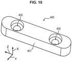
- the coupling device comprises a first coupling part fixed to the central rotating shaft and a second coupling part fixed in the shoulder fixing part, the first part d coupling cooperating by a sliding connection with the second coupling part along the first axis of rotation and solidarity in rotation with the second coupling part.
- the first coupling part projects from the central rotating shaft transversely to the first axis of rotation
- the second coupling part is a groove, which extends on an inner surface of the shoulder attachment part along the first axis of rotation and in which the first coupling part can be moved in translation along the first axis of rotation by being blocked in rotation around the first axis of rotation.
- the friction stir welding head 1 comprises a frame 300, intended to be fixed to a frame C of a machine M separate from the head 1, the welding head 1 having to be mounted on the machine M.
- This machine M can be a machine tool M, for example a numerically controlled machine tool M.
- the machine M includes a drive spindle B (or spindle nose B), which is rotatably mounted around an axis AX2 relative to the frame C.
- This friction stir welding tool O comprises a peripheral shoulder 100 and a rotating and retractable central pin 200, which is surrounded by the peripheral shoulder 100 around a first axis AX1 of rotation and which is capable of projecting relative to the peripheral shoulder 100 along the first axis AX1 of rotation.
- the shoulder peripheral 100 is separated from the central pin 200, that is to say that the peripheral shoulder 100 is not in one piece with the central pin 200.
- the peripheral shoulder 100 has a lower transverse welding surface 101 to the first axis AX1 of rotation, while the central pin 200 extends along the first axis AX1 of rotation.
- the first axis AX1 of rotation can for example be vertical and parallel to a vertical direction Z, oriented in the upward direction, to which a horizontal direction horizontal X, are perpendicular.
- friction stir welding (FSW for “Friction Stir Welding”) is carried out by rotating the peripheral shoulder 100 and the central pin 200 around the first axis AX1 of rotation (according to arrow R), to penetrate the central pin 200 in two (or more than two) pieces to be welded or pieces to be worked P1 and P2, until the shoulder 100 abuts against these pieces P1 and P2, then movement of the tool O according to a prescribed trajectory D along an LJ joint line to make the SFSW friction stir weld.
- the head 1 comprises a rotating central shaft 201 to which, in a mounting position of the tool O on the head 1, the central pin 200 is fixed.
- the head 1 comprises a shoulder fixing part 301 to which, in a mounting position of the tool O on the head 1, the peripheral shoulder 100 is fixed.
- the shoulder fixing part 301 is located around the central shaft 201, which exceeds this shoulder fixing part 301 upwards, as shown in figures 5 , 6 And 8 .
- the shoulder fixing part 301 is centered on the same axis AX1 as the rotating central shaft 201.
- the shoulder fixing part 301 can for example be circular.
- the mechanical coupling system 400 in mechanical rotation between the part 201 and the part 301 allows a degree of freedom in translation between the part 201 and the part 301.
- the shoulder fixing part 301 is fixed to the rotary primary shaft 302 drive, for example by removable fixing means 304 operable from the outside, which may for example be one or more external screws 304.
- removable fixing means 304 operable from the outside, which may for example be one or more external screws 304.
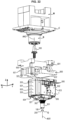
- the primary rotary drive shaft 302 is mounted by a rotation support bearing 322 or bearing (for example a ball bearing) on a lower part of a casing 321 of the frame 300. From this casing 321 protrude downwards the shoulder fixing part 301, the peripheral shoulder 100 and the central pin 200 when it protrudes from the peripheral shoulder 100.
- a rotation support bearing 322 or bearing for example a ball bearing
- the rotation of the spindle B of the machine M causes the rotation of the external interface part 350 around the second axis AX2 of rotation of this external interface part 350, which drives, via the first rotation transmission device 310, the rotation of the rotary primary shaft 302.
- Embodiments of this first rotation transmission device 310 are described below, as well as shown in figures 5 to 8 .
- the first rotation transmission device 310 comprises a secondary shaft 311 connected to and integral in rotation with the external interface part 350 around the second axis AX2 of rotation.
- a first pulley 312 is fixed to the secondary shaft 311 around the second axis AX2 of rotation
- a second pulley 313 is fixed to the primary rotating shaft 302 around the first axis AX1 of rotation
- a belt 314 for transmitting rotation is arranged around the first pulley 312 and around the second pulley 313.
- the belt 314 makes it possible to transmit the rotation of the external interface part 350 around the second axis AX2 of rotation to the rotary primary shaft 302 around the first axis AX1 of rotation .
- the first rotation transmission device 310 can be gear or other between the external interface part 350 and the rotary primary shaft 302.
- the head 1 comprises a motor 250 for actuating the retractable pin 200 and a second device 210 for driving the rotating central shaft 201 in translation along the first axis AX1 of rotation from the motor 250 and this during rotation of the central rotating shaft 201 and the shoulder fixing part 301 around the first axis AX1 of rotation and therefore during the rotation of the peripheral shoulder 100 and the central pin 200 around the first axis AX1 of rotation, when this peripheral shoulder 100 is mounted on the shoulder fixing part 301 and when this central pin 200 is mounted on the central rotating shaft 201.
- the second translation drive device 210 makes it possible to translate the central rotating shaft 201 relative to to the shoulder fixing part 301 and to the rotary primary shaft 302 of at least one low position of the central rotary shaft 201, shown in figures 1 , 2 , 3 , 5 , 11 And 13 , in which the lower end 202 of the central pin 200 projects downwards relative to the peripheral shoulder 100 and its lower surface 101 along the first axis AX1 of rotation, at a high position of the central rotating shaft 201 , represented at figures 6 , 12 And 14 , in which the central pin 200 does not protrude downwards relative to the peripheral shoulder 100 and its lower surface 101 along the first axis AX1 of rotation.
- step E3 the head 1 is lowered by the control device of the machine M, for example towards the part P1 and/or P2, to lower the peripheral shoulder 100 and the central pin 200 projecting out of the peripheral shoulder 100, which both rotate around the first axis AX1 of rotation, against the part P1 and/or P2.
- step E4 the raising of the central pin 200 in translation relative to the peripheral shoulder 100 so that the lower end 202 of the central pin 200 is lowered into an intermediate or low position or is raised into an intermediate position or retracted in the peripheral shoulder 100 in the high position (step E4), and this for example during the rotation of the first transmission device 310 around the second axis AX2 and during the rotation of the rotary primary shaft assembly 302, shoulder fixing part 301, pin central 200 and peripheral shoulder 100 around the first axis AX1 of rotation.
- the lower end 202 of the central pin 200 can be at the same level as the lower surface 101 of the peripheral shoulder 100 or at a level higher than the lower surface 101 of the peripheral shoulder 100.
- the raising of the central pin 200 at least up to the high position advantageously makes it possible to leave in the SFSW welding line an almost flat and horizontal surface, filled with material below the lower end 202 of the central pin 200 and below the peripheral shoulder 100, without leaving a hole in this SFSW weld line under it.
- head 1 is raised relative to parts P1 and P2 (step E5).
- the head 1 makes it possible to reach the forces necessary at the lower end 202 of the central pin 200 to carry out the filling of this hole or to weld several thicknesses in the same weld.
- the translation of the central pin 200 along the first axis AX1 could be implemented by offsetting the second rotational drive axis AX2 of the welding tool O thanks to the first rotation transmission device 310.
- the welding head 1 forms an effector 1.
- the upper surface 323 of the welding head 1 and/or the housing 500 is fixed to an adapter 600 (or adaptation part 600 or fixing part 600 ).
- the adapter 600 is fixed to the chassis C of the machine M.
- the welding head 1 and/or the upper surface 323 and/or the housing 500 may include fixing or assembly members 506, for fixing or assembling the head 1 of welding and/or the upper surface 323 and/or the housing 500 to the adapter 600.
- the adapter 600 may include fixing or assembly members 601, for fixing or assembling the adapter 600 to the chassis C of the machine M.
- the fixing members 506 can be or include for example screws 506 or bolts 506, or rods 506, or others.
- the fixing members 601 can be or include for example screws 601 or bolts 601, or rods 601, or others.
- the adapter 600 comprises a through hole 602 through which the external interface part 350 passes in the mounting position of the welding head 1 on the machine M. In the mounting position of the welding head 1 on the machine M , the external interface part 350 is fixed to spindle B of machine M, for example by a mechanical coupling. In the mounting position of the welding head 1 on the machine M, the adapter 600 is located between the frame C and the upper surface 323.
- the adapter 600 is in one piece with the housing 500 of the welding head 1 and is inseparable from the housing 500 of the welding head 1.
- the fixing members 506 are not provided.
- the motor 250 comprises a tertiary shaft 251 rotating around a third axis AX3 of rotation.
- the second translation drive device 210 comprises an intermediate shaft 221, which is offset above the central shaft 201 and which is coaxial with the first axis AX1 of rotation.
- a mechanism 220 for transmitting rotation of the rotary tertiary shaft 251 of the motor 250 around its third axis AX3 of rotation to the intermediate shaft 221 around the first axis AX1 of rotation is provided in the second translation drive device 210 .
- a mechanism 230 for transforming the rotation of the intermediate shaft 221 around the first axis AX1 of rotation into a translation of the central shaft 201 along the first axis AX1 of rotation is provided in the second device 210 of translational drive.
- the third axis AX3 of rotation of the tertiary shaft 251 of the motor 250 is offset and transverse to the first axis AX1 of rotation, and can for example make a non-zero angle and for example perpendicular to the first axis AX1 of rotation.
- the rotation transmission mechanism 220 comprises an angle transmission mechanism 225 from the tertiary shaft 251 rotating around the third axis AX3 of rotation to the intermediate shaft 221 around the first axis AX1 of rotation.
- the angle transmission mechanism 225 of the rotary tertiary shaft 251 comprises at least one first meshing member 222 fixed to the tertiary shaft 251 and at least one second meshing member 223 fixed to the intermediate shaft 221 and meshing with the first meshing member 222, the second meshing member 223 being rotated around the first axis AX1 of rotation by the rotation of the first meshing member 222 around the third axis AX3 of rotation, these members 22 and 223 forming an angle gear.
- the intermediate shaft 221 is rotatably mounted around the first axis AX1 of rotation without possible translation along this first axis AX1 of rotation on an internal plate 226, which is mounted in the frame 300 and is fixed to the casing 321.
- intermediate shaft 221 can be mounted by a rotation support bearing 227 or bearing 227 (for example a ball bearing 227) on the inner plate 226 and can pass through the inner plate 226.
- figures 5 to 8 And 10 to 12 the rotation support bearing 227 or bearing 227 and the inner plate 226 are located between the second toothed wheel 223 located at the top in the inner plate 226 and the rotation transformation mechanism 230, located lower in the frame 300.
- the nut 232 can be formed by a ring 232 whose internal thread is screwed onto the external thread 231 of the screw of the lower part of the shaft 221.
- the nut 232 and the screw 231 of the lower part of the The shaft 221 can be of the ball screw type, that is to say with balls between the nut 232 and the screw 231.
- the rotation blocking element 233 can be formed by a tongue 233 projecting downwards along and at a distance from the first axis AX1 of rotation, this tongue 233 being fixed under the inner plate 226 and having a flat surface, which is parallel to the first axis AX1 of rotation and which bears externally against a flat surface (for example flat), also parallel to the first axis AX1 of rotation, of the second member 232 and/or the sleeve 234.
- the rotation support bearing 235 is a bearing assembly 235, comprising at least a first bearing part 2351 fixed to the second side 2342 of the sleeve 234 and at least a second bearing part 2352, which is fixed to the central shaft 201 and which is rotatable relative to the first rolling part 2351.
- the sleeve 234 is located in an upper interior cavity 303 of the rotary primary shaft 302 and is surrounded by a circular cylindrical wall 305 of the rotary primary shaft 302, this circular cylindrical wall 305 delimiting the interior cavity 303 around the first axis AX1 rotation.
- the sleeve 234 is movable in translation along the first axis AX1 of rotation in the interior cavity 303.
- the circular cylindrical wall 305 is extended downwards by the part of the rotary primary shaft 302 emerging towards the outside of the casing 321 of the frame 300 and carrying the shoulder fixing part 301.
- the intermediate shaft 221 and the first member 231 of the lower part of the shaft 221 rotate in a second direction prescribed around the first axis AX1 of rotation, which causes this second member 232 and the sleeve 234 to rise, due to the blocking of rotation of the second member 232 by the element 233, along the first axis AX1 of rotation, for example for move from the position of figures 5 And 11 at the position of figures 6 And 12 .
Landscapes
- Engineering & Computer Science (AREA)
- Mechanical Engineering (AREA)
- Pressure Welding/Diffusion-Bonding (AREA)
- Transmission Devices (AREA)
Claims (17)
- Kopf (1) für Rührreibschweißen, der zur Befestigung an einer Maschine (M) zur Durchführung eines Rührreibschweißens mit Hilfe eines Werkzeugs bestimmt ist, das einen umlaufenden Mantel (100) und einen zentralen Stift (200) aufweist, der von dem umlaufenden Mantel (100) um eine erste Rotationsachse (AX) umgeben ist und der imstande ist, im Verhältnis zu dem umlaufenden Mantel (100) hervorzustehen,wobei der Kopf (1) einen Rahmen (300) aufweist, der zur Befestigung an einem Gestell (C) der Maschine (M) bestimmt ist,wobei der Kopf (1) eine zentrale rotierende Welle (201) aufweist, an der der zentrale Stift (200) bestimmt ist, befestigt zu sein, ein Mantelbefestigungsteil (301), das sich um die zentrale Welle (201) befindet und an dem der umlaufende Mantel (100) bestimmt ist, befestigt zu sein,wobei der Kopf (1) ferner eine primäre rotierende Welle (302) aufweist, die gleichzeitig das Mantelbefestigungsteil (301) und die zentrale rotierende Welle (201) um die erste Rotationsachse (AX1) rotierend antreibt,wobei die rotierende Welle (201) und das Mantelbefestigungsteil (301) eine Vorrichtung (400) zur Kopplung aneinander haben, damit die zentrale rotierende Welle (201) mit dem Mantelbefestigungsteil (301) um die erste Rotationsachse (AX1) rotatorisch fest verbunden ist und damit die zentrale rotierende Welle (201) im Verhältnis zum Mantelbefestigungsteil (301) entlang der ersten Rotationsachse (AX1) translatorisch frei ist,wobei der Kopf (1) einen Motor (250) und eine zweite Vorrichtung (210) zum Translationsantrieb der zentralen rotierenden Welle (201) entlang der ersten Rotationsachse (AX1) durch den Motor (250) während der Rotation der zentralen rotierenden Welle (201) und des Mantelbefestigungsteils (301) um die erste Rotationsachse (AX1) zwischen mindestens einer niedrigen Position der zentralen rotierenden Welle (201), in welcher der zentrale Stift (200) im Verhältnis zum umlaufenden Mantel (100) gemäß der ersten Rotationsachse (AX1) hervorsteht, und einer hohen Position der zentralen rotierenden Welle (201), in welcher der zentrale Stift (200) im Verhältnis zum umlaufenden Mantel (100) gemäß der ersten Rotationsachse (AX1) nicht hervorsteht, aufweist,dadurch gekennzeichnet, dass der Kopf (1) ein äußeres Schnittstellenteil (350), das zur Befestigung an einer rotierenden Spindel (B) der Maschine (M) bestimmt ist und eine erste Vorrichtung (310) zur Übertragung der Rotation des äußeren Schnittstellenteils (350) an die primäre rotierende Welle (302) um die erste Rotationsachse (AX1) aufweist, wobei das äußere Schnittstellenteil (350) eine äußere Oberfläche (323) des Rahmens (300) überragt.
- Kopf nach Anspruch 1, dadurch gekennzeichnet, dass die erste Rotationsachse (AX1), die zentrale rotierende Welle (201) und die primäre rotierende Welle (302) versetzt und parallel im Verhältnis zu einer zweiten Rotationsachse (AX2) des äußeren Schnittstellenteils (350) sind.
- Kopf nach einem beliebigen der vorangehenden Ansprüche, dadurch gekennzeichnet, dass die erste Vorrichtung (310) zur Übertragung der Rotation eine sekundäre Welle (311), die mit dem äußeren Schnittstellenteil (350) um die zweite Rotationsachse (AX2) rotatorisch fest verbunden ist, eine erste Scheibe (312), die um die sekundäre Welle (311) befestigt ist, eine zweite Scheibe (313), die um die primäre rotierende Welle (302) befestigt ist und einen Riemen (314) zur Übertragung der Rotation zwischen der ersten Scheibe (312) und der zweiten Scheibe (313) aufweist, um die Rotation des äußeren Schnittstellenteils (350) um die zweite Rotationsachse (AX2) auf die primäre rotierende Welle (302) um die erste Rotationsachse (AX1) zu übertragen.
- Kopf nach einem beliebigen der vorangehenden Ansprüche, dadurch gekennzeichnet, dass der Motor (250) eine tertiäre rotierende Welle (251) um eine dritte Rotationsachse (AX3) aufweist,
wobei die zweite Vorrichtung (210) zum Translationsantrieb eine Übergangswelle (221), die im Verhältnis zur zentralen Welle (201) koaxial und versetzt ist, einen Mechanismus (220) zur Übertragung der Rotation der tertiären rotierenden Welle (251) um die dritte Rotationsachse (AX3) auf die Übergangswelle (221) um die erste Rotationsachse (AX1) und einen Mechanismus (230) zur Umwandlung der Rotation der Übergangswelle (221) um die erste Rotationsachse (AX1) in Translation der zentralen Welle (201) entlang der ersten Rotationsachse (AX1) aufweist. - Kopf nach Anspruch 4, dadurch gekennzeichnet, dass die tertiäre Welle (251) des Motors (250) um die versetzte und im Verhältnis zur ersten Rotationsachse (AX1) querliegende dritte Rotationsachse (AX3) rotierend ist,
wobei der Mechanismus (220) zur Übertragung der Rotation einen Winkeltriebmechanismus (225) der um die dritte Rotationsachse (AX3) rotierenden tertiären Welle (251) auf die Übergangswelle (221) um die erste Rotationsachse (AX1) aufweist. - Kopf nach Anspruch 5, dadurch gekennzeichnet, dass der Winkeltriebmechanismus (225) der rotierenden tertiären Welle (251) mindestens eine erste Schnecke (222) aufweist, die mit der tertiären Welle (251) rotatorisch fest verbunden ist, und mindestens ein zweites Zahnrad (223), das um die Übergangswelle (221) rotatorisch fest verbunden ist, wobei die zweite Schnecke (223) in das erste Zahnrad (222) eingreift.
- Kopf nach einem beliebigen der Ansprüche 4 bis 6, dadurch gekennzeichnet, dass der Mechanismus (230) zur Umwandlung der Rotation ein erstes Außengewindeorgan (231) aufweist, das an der Übergangswelle (221) befestigt ist oder von ihr gebildet wird, ein zweites Innengewindeorgan (232), das mit der zentralen Welle (201) entlang der ersten Rotationsachse (AX1) translatorisch fest verbunden ist, und ein Rotationsblockierelement (233) des zweiten Innengewindeorgans (232),wobei das erste Außengewindeorgan (232) mittels einer Schraubverbindung mit dem zweiten Innengewindeorgan (232) um die erste Rotationsachse (AX1) zusammenwirkt,wobei das Blockierelement (233) an einer inneren Platte (226) befestigt ist, auf der die Übergangswelle (221) rotatorisch angebracht ist, wobei die innere Platte (226) im Rahmen (300) angebracht ist.
- Kopf nach Anspruch 7, dadurch gekennzeichnet, dass das erste Außengewindeorgan (231) eine Schraube (231) ist, die an der Übergangswelle (221) befestigt oder von ihr gebildet ist, wobei das zweite Innengewindeorgan (232) eine Mutter (232) ist, die um die Schraube (231) geschraubt ist.
- Kopf nach einem beliebigen der Ansprüche 4 bis 6, dadurch gekennzeichnet, dass der Mechanismus (230) zur Umwandlung der Rotation ein ersten Innengewindeorgan (231) aufweist, das an der Übergangswelle (221) befestigt oder von ihr gebildet wird, ein zweites Außengewindeorgan (232), das mit der zentralen Welle (201) entlang der ersten Rotationsachse (AX1) translatorisch fest verbunden ist, und ein Rotationsblockierelement (233) des ersten Innengewindeorgans (231),wobei das erste Innengewindeorgan (231) mittels einer Schraubverbindung mit dem zweiten Außengewindeorgan (232) um die erste Rotationsachse (AX1) zusammenwirkt,wobei das Blockierelement (233) an einer inneren Platte (226) befestigt ist, auf der die Übergangswelle (221) rotatorisch angebracht ist, wobei die innere Platte (226) im Rahmen (300) angebracht ist,wobei das erste Innengewindeorgan (231) eine Mutter ist, die an der Übergangswelle (221) befestigt ist, wobei das zweite Außengewindeorgan (232) eine Schraube ist, wobei die Mutter um die Schraube geschraubt ist.
- Kopf nach einem beliebigen der Ansprüche 7 bis 9, dadurch gekennzeichnet, dass der Mechanismus (230) zur Umwandlung der Rotation eine Hülse (234) aufweist, die eine erste Seite (2341) aufweist, die um das zweite Organ (232) befestigt ist, und eine zweite Seite (2342), in der ein Rotationsstützlager (235) der zentralen Welle (201) um die erste Rotationsachse (AX1) befestigt ist.
- Kopf nach Anspruch 10, dadurch gekennzeichnet, dass das Rotationsstützlager (235) eine Lagermontage (235) ist, die mindestens einen ersten Lagerteil (2351) aufweist, der in der zweiten Seite (2342) der Hülse (234) befestigt ist, und mindestens einen zweiten Lagerteil (2352), der an der zentralen Welle (201) befestigt ist und der im Verhältnis zum ersten Lagerteil (2351) rotatorisch ist.
- Kopf nach Anspruch 10 oder 11, dadurch gekennzeichnet, dass die Hülse (234) in einen inneren Hohlraum (303) der primären rotierende Wellen (302) eingesetzt und translatorisch entlang der ersten Rotationsachse (AX1) im inneren Hohlraum (303) beweglich ist.
- Kopf nach einem beliebigen der vorangehenden Ansprüche, dadurch gekennzeichnet, dass die Kopplungsvorrichtung (400) einen ersten Kopplungsteil (401) aufweist, der an der zentralen rotierenden Welle (201) befestigt ist, und einen zweiten Kopplungsteil (402), der im Mantelbefestigungsteil (301) befestigt ist, wobei der erste Kopplungsteil (401) mittels einer Gleitverbindung mit dem zweiten Kopplungsteil (402) entlang der ersten Rotationsachse (AX1) und rotatorisch mit dem zweiten Kopplungsteil (402) fest verbunden zusammenwirkt.
- Kopf nach Anspruch 13, dadurch gekennzeichnet, dass der erste Kopplungsteil (401) auf der zentralen rotierenden Welle (201) quer zur ersten Rotationsachse (AX1) hervorsteht, der zweite Kopplungsteil (402) eine Nut (402) ist, die sich auf einer inneren Oberfläche (403) des Mantelbefestigungsteils (301) entlang der ersten Rotationsachse (AX1) erstreckt und in welcher der erste Kopplungsteil (401) translatorisch entlang der ersten Rotationsachse (AX1) bewegbar ist, indem er um die erste Rotationsachse (AX1) rotatorisch blockiert ist.
- Kopf nach einem beliebigen der vorangehenden Ansprüche, dadurch gekennzeichnet, dass der zentrale Stift (200) in der hohen Position oberhalb einer unteren Oberfläche (101) des umlaufenden Mantels (100) eingezogen ist.
- Kopf nach einem beliebigen der vorangehenden Ansprüche, dadurch gekennzeichnet, dass das Mantelbefestigungsteil (301) und der umlaufende Mantel (100) aus einem einzigen Teil sind.
- Rührreibschweißverfahren von Teilen (P1, P2), gekennzeichnet durch die folgenden Schritte:Anbringen des Rahmens (300) des Schweißkopfs (1) nach einem beliebigen der vorangehenden Ansprüche auf einer Maschine (M),wobei das äußere Schnittstellenteil (350) des Kopfs (1) eine obere Oberfläche (323) des Rahmens (300) des Schweißkopfs (1) überragt und an einer rotierenden Spindel (B) der Maschine (M) befestigt ist,Steuern (E1), durch eine Steuervorrichtung des Motors (250), des Heraustretens des zentralen Stifts (200) aus dem umlaufenden Mantel (100) bis in eine niedrige Position,Steuern (E2), durch eine Steuervorrichtung der Maschine (M), der Rotation der Spindel (B) der Maschine (M), um die Rotation des umlaufenden Mantels (100) und des zentralen Stifts (200) um die erste Rotationsachse (AX1) zu bewirken,Absenken (E3), durch die Steuervorrichtung der Maschine (M), des Kopfs (1) zu den Teilen (P1, P2), um den umlaufenden Mantel (100) und den zentralen Stift (200), der aus dem umlaufenden Mantel (100) hervorsteht, die beide um die erste Rotationsachse (AX1) drehen, auf die Teile (P1, P2) abzusenken,Steuern (E4) der Translation des zentralen Stifts (200) im Verhältnis zum umlaufenden Mantel (100) durch die Steuervorrichtung des Motors (250), damit ein unteres Ende (202) des zentralen Stifts (200) im Verhältnis zum umlaufenden Mantel (100) angenähert oder entfernt wird, währenddessen einerseits der umlaufende Mantel (100), der sich auf den Teilen (P1, P2) abgestützt, und zum anderen der zentrale Stift (200) beide um die erste Rotationsachse (AX1) drehen,Beabstanden (E5) des Kopfs (1) im Verhältnis zu den Teilen (P1, P2).
Applications Claiming Priority (1)
| Application Number | Priority Date | Filing Date | Title |
|---|---|---|---|
| FR2103957A FR3121855B1 (fr) | 2021-04-16 | 2021-04-16 | Tête de soudage par friction malaxage et procédé l’utilisant |
Publications (3)
| Publication Number | Publication Date |
|---|---|
| EP4074452A1 EP4074452A1 (de) | 2022-10-19 |
| EP4074452C0 EP4074452C0 (de) | 2023-11-15 |
| EP4074452B1 true EP4074452B1 (de) | 2023-11-15 |
Family
ID=76375211
Family Applications (1)
| Application Number | Title | Priority Date | Filing Date |
|---|---|---|---|
| EP22166634.0A Active EP4074452B1 (de) | 2021-04-16 | 2022-04-05 | Schweisskopf für rührreibschweissverfahren und verfahren unter verwendung eines solchen schweisskopfes |
Country Status (4)
| Country | Link |
|---|---|
| US (1) | US12023753B2 (de) |
| EP (1) | EP4074452B1 (de) |
| CA (1) | CA3156030A1 (de) |
| FR (1) | FR3121855B1 (de) |
Families Citing this family (6)
| Publication number | Priority date | Publication date | Assignee | Title |
|---|---|---|---|---|
| CN112453681B (zh) * | 2020-10-22 | 2022-06-14 | 北京工业大学 | 一种可回抽的搅拌摩擦焊电主轴 |
| CN118574695B (zh) * | 2022-04-28 | 2025-07-29 | 山崎马扎克公司 | 摩擦搅拌接合工具、摩擦搅拌接合装置和摩擦搅拌接合方法 |
| US12583054B2 (en) | 2023-03-24 | 2026-03-24 | National Chung Cheng University | Adaptive tool holder for robotic arm |
| CN117001137B (zh) * | 2023-09-22 | 2023-12-15 | 江苏攀森智能科技有限公司 | 一种电机壳搅拌摩擦焊用分体快换式刀具及更换方法 |
| JP7445355B1 (ja) * | 2023-11-01 | 2024-03-07 | 京浜ラムテック株式会社 | 摩擦撹拌用回転部材、接合装置、及び接合方法 |
| CN119238032A (zh) * | 2024-10-16 | 2025-01-03 | 中国直升机设计研究所 | 一种损伤孔再制造修复装置和方法 |
Family Cites Families (28)
| Publication number | Priority date | Publication date | Assignee | Title |
|---|---|---|---|---|
| US6484924B1 (en) * | 2001-08-14 | 2002-11-26 | The Boeing Company | Method and apparatus for backing up a friction stir weld joint |
| US6732900B2 (en) * | 2002-04-02 | 2004-05-11 | Mts Systems Corporation | Friction stir welding spindle with axially displaceable spindle shaft |
| JP2004136331A (ja) * | 2002-10-18 | 2004-05-13 | Hitachi Ltd | 摩擦攪拌接合装置及び接合方法 |
| JP2005211971A (ja) * | 2004-01-30 | 2005-08-11 | Mitsubishi Motors Corp | 摩擦撹拌接合装置 |
| US7641096B2 (en) * | 2005-01-24 | 2010-01-05 | The Boeing Company | Friction stir welding apparatus |
| US8052030B2 (en) * | 2005-01-24 | 2011-11-08 | The Boeing Company | Apparatus for friction stir welding using spindle-in-spindle |
| JP4754256B2 (ja) * | 2005-04-19 | 2011-08-24 | 住友軽金属工業株式会社 | 摩擦撹拌点接合用回転工具及びそれを用いた摩擦撹拌点接合方法 |
| JP4628218B2 (ja) * | 2005-08-22 | 2011-02-09 | Obara株式会社 | 摩擦撹拌スポット接合装置 |
| JP4853864B2 (ja) * | 2006-02-20 | 2012-01-11 | Obara Group株式会社 | Fswの接合ツ―ルの清掃方法 |
| US7641739B2 (en) * | 2006-06-13 | 2010-01-05 | The Boeing Company | Friction stir welding tool cleaning method |
| US9511461B2 (en) * | 2006-10-05 | 2016-12-06 | The Boeing Company | Independent axis ancillary device |
| JP4325875B2 (ja) * | 2006-11-06 | 2009-09-02 | 株式会社日立製作所 | 摩擦攪拌接合用ツール及び摩擦攪拌接合装置 |
| WO2009098836A1 (en) * | 2008-02-08 | 2009-08-13 | Fuji Electric Fa Components & Systems Co., Ltd. | Manufacturing method of electric contact and manufacturing equipment of electric contact |
| US20090294511A1 (en) * | 2008-05-30 | 2009-12-03 | Vanderbilt University | Lateral position detection for friction stir systems |
| US20100072261A1 (en) * | 2008-09-25 | 2010-03-25 | Marcio Fernando Cruz | Friction stir welding spindle downforce and other control techniques, systems and methods |
| US8261959B2 (en) * | 2008-09-25 | 2012-09-11 | Embraer S.A. | Friction stir welding spindle downforce and other control techniques, systems and methods |
| JP5463736B2 (ja) * | 2009-06-02 | 2014-04-09 | Obara Group株式会社 | 圧電型ロ―ドセルを組込んだ中空駆動ユニット |
| JP5631162B2 (ja) * | 2010-11-16 | 2014-11-26 | カルソニックカンセイ株式会社 | 摩擦攪拌接合方法 |
| US9387551B2 (en) * | 2012-09-06 | 2016-07-12 | Apple Inc. | Method, system, and computer program product for simulating friction stir welding |
| DE102014010058B4 (de) * | 2014-07-07 | 2016-01-28 | Grenzebach Maschinenbau Gmbh | Verfahren und Vorrichtung zum schnellen und sicheren Werkzeugwechsel bei dem Vorgang des Rührreibschweißens und ein Computerprogramm zur Durchführung des Verfahrens |
| PT3069812T (pt) * | 2015-03-18 | 2017-12-21 | Helmholtz-Zentrum Geesthacht Zentrum für Material-und Küstenforschung GmbH | Aparelho para soldadura por fricção linear com um contacto que compreende primeiro e segundo orifícios de passagem |
| DE102016007585B3 (de) * | 2016-06-21 | 2017-11-02 | Grenzebach Maschinenbau Gmbh | Vorrichtung und Verfahren zum Verschweißen zweier Fügepartner mittels Rührreibschweißen durch die, bzw. durch das, keinerlei Kontamination der Fügepartner durch Schweiß - Rückstände erfolgt, sowie ein Computerprogramm zur Durchführung des Verfahrens |
| JP6637181B2 (ja) * | 2016-08-10 | 2020-01-29 | 株式会社東芝 | 摩擦撹拌接合装置、加工位置設定装置、および測定装置 |
| US20180056436A1 (en) * | 2016-08-26 | 2018-03-01 | The Boeing Company | Systems, methods, and devices for exit hole repair associated with welding operations |
| WO2019089764A1 (en) * | 2017-10-31 | 2019-05-09 | Aeroprobe Corporation | Solid-state additive manufacturing system and material compositions and structures |
| AT522421A1 (de) * | 2019-02-25 | 2020-10-15 | Stirtec Gmbh | Verfahren zum Fügen oder Zerspanen sowie Vorrichtung hierzu |
| EP3965025A1 (de) * | 2020-08-21 | 2022-03-09 | Tata Consultancy Services Limited | Verfahren und system zur multisensorfusion mittels transformationslernen |
| JP6892544B1 (ja) * | 2020-10-28 | 2021-06-23 | 株式会社日立パワーソリューションズ | 摩擦攪拌接合装置及び摩擦攪拌接合方法 |
-
2021
- 2021-04-16 FR FR2103957A patent/FR3121855B1/fr not_active Expired - Fee Related
-
2022
- 2022-04-05 EP EP22166634.0A patent/EP4074452B1/de active Active
- 2022-04-14 US US17/720,690 patent/US12023753B2/en active Active
- 2022-04-14 CA CA3156030A patent/CA3156030A1/fr active Pending
Also Published As
| Publication number | Publication date |
|---|---|
| CA3156030A1 (fr) | 2022-10-16 |
| EP4074452A1 (de) | 2022-10-19 |
| FR3121855B1 (fr) | 2024-04-19 |
| US20220331897A1 (en) | 2022-10-20 |
| FR3121855A1 (fr) | 2022-10-21 |
| EP4074452C0 (de) | 2023-11-15 |
| US12023753B2 (en) | 2024-07-02 |
Similar Documents
| Publication | Publication Date | Title |
|---|---|---|
| EP4074452B1 (de) | Schweisskopf für rührreibschweissverfahren und verfahren unter verwendung eines solchen schweisskopfes | |
| EP0227694B1 (de) | Antriebsvorrichtung zum verstellen eines elementes, insbesondere eines sitzes oder von teilen eines fahrzeugsitzes relativ zum rahmen | |
| EP3389913B1 (de) | Reibschweisskopf mit kupplungselementen und mindestens einem elastischen element | |
| EP2440482B1 (de) | Breiteneinstellungsvorrichtung für fördergänge | |
| EP3145790B1 (de) | In die tiefe einstellbarer lenksäulemechanismus mit versenkbarem anschlag | |
| EP0194217B1 (de) | Industrieroboter vom sphärischen Typ | |
| FR2984192A1 (fr) | Procede d'usinage | |
| FR2593728A1 (fr) | Poinconneuse a entrainement equilibre | |
| EP0588713B1 (de) | Fräs-, Planfräs- und Polier-Maschine für automatischen Werkzeugwechsel und entsprechende Vorrichtung | |
| EP4227035A1 (de) | Arbeitsschnittstellenzubehör, arbeitskit mit einem solchen zubehör, und reibrührschweissverfahren unter verwendung eines solchen kits | |
| FR3121622A1 (fr) | Tete de prehension et de poinçonnage d’une piece permettant son entrainement en rotation pour son usinage | |
| EP1493529B1 (de) | Montagemaschine mit einem Montagewerkzeuge tragenden Revolver | |
| EP2274117B1 (de) | Versorgungsstation | |
| EP2790894B1 (de) | Automatisierte vorrichtung zur plasmaoberflächenbearbeitung eines wärmehärtenden teils | |
| FR2951392A1 (fr) | Installation de soudage au laser | |
| FR3046096A1 (fr) | Tete de friction malaxage universelle pour centre d'usinage | |
| EP1345710A1 (de) | Vorrichtung und verfahren zur herstellung von anschlussstutzen in einer abgasanlage | |
| FR2711085A1 (fr) | Machine automatique de déplacement dans l'espace d'un outil de travail, notamment d'usinage. | |
| FR2892960A1 (fr) | Machine-outil | |
| EP3633236B1 (de) | Getriebegehäuse einer servolenkung, das einen schlitz auf einer seite einer zwischenbohrung umfasst | |
| EP4084922B1 (de) | Elektrospindel mit integriertem vortrieb mit automatischem werkzeughalterwechsel | |
| FR3120600A1 (fr) | dispositif pilote destiné à être utilisé sur un gabarit de montage | |
| WO2015097392A1 (fr) | Outil rotatif d'enlèvement de matière d'une pièce en matière plastique | |
| FR3074709B1 (fr) | Outil a main pour la rectification du diametre d’un element de positionnement tel qu’un pion de centrage | |
| WO2024074798A2 (fr) | Systeme de travail de piece comprenant une machine-outil, et procede de travail correspondant |
Legal Events
| Date | Code | Title | Description |
|---|---|---|---|
| PUAI | Public reference made under article 153(3) epc to a published international application that has entered the european phase |
Free format text: ORIGINAL CODE: 0009012 |
|
| STAA | Information on the status of an ep patent application or granted ep patent |
Free format text: STATUS: THE APPLICATION HAS BEEN PUBLISHED |
|
| AK | Designated contracting states |
Kind code of ref document: A1 Designated state(s): AL AT BE BG CH CY CZ DE DK EE ES FI FR GB GR HR HU IE IS IT LI LT LU LV MC MK MT NL NO PL PT RO RS SE SI SK SM TR |
|
| STAA | Information on the status of an ep patent application or granted ep patent |
Free format text: STATUS: REQUEST FOR EXAMINATION WAS MADE |
|
| 17P | Request for examination filed |
Effective date: 20230118 |
|
| RBV | Designated contracting states (corrected) |
Designated state(s): AL AT BE BG CH CY CZ DE DK EE ES FI FR GB GR HR HU IE IS IT LI LT LU LV MC MK MT NL NO PL PT RO RS SE SI SK SM TR |
|
| GRAP | Despatch of communication of intention to grant a patent |
Free format text: ORIGINAL CODE: EPIDOSNIGR1 |
|
| STAA | Information on the status of an ep patent application or granted ep patent |
Free format text: STATUS: GRANT OF PATENT IS INTENDED |
|
| RIC1 | Information provided on ipc code assigned before grant |
Ipc: B23K 20/12 20060101AFI20230614BHEP |
|
| INTG | Intention to grant announced |
Effective date: 20230706 |
|
| GRAS | Grant fee paid |
Free format text: ORIGINAL CODE: EPIDOSNIGR3 |
|
| GRAA | (expected) grant |
Free format text: ORIGINAL CODE: 0009210 |
|
| STAA | Information on the status of an ep patent application or granted ep patent |
Free format text: STATUS: THE PATENT HAS BEEN GRANTED |
|
| AK | Designated contracting states |
Kind code of ref document: B1 Designated state(s): AL AT BE BG CH CY CZ DE DK EE ES FI FR GB GR HR HU IE IS IT LI LT LU LV MC MK MT NL NO PL PT RO RS SE SI SK SM TR |
|
| REG | Reference to a national code |
Ref country code: CH Ref legal event code: EP Ref country code: GB Ref legal event code: FG4D Free format text: NOT ENGLISH |
|
| REG | Reference to a national code |
Ref country code: DE Ref legal event code: R096 Ref document number: 602022000978 Country of ref document: DE |
|
| REG | Reference to a national code |
Ref country code: IE Ref legal event code: FG4D Free format text: LANGUAGE OF EP DOCUMENT: FRENCH |
|
| U01 | Request for unitary effect filed |
Effective date: 20231214 |
|
| U07 | Unitary effect registered |
Designated state(s): AT BE BG DE DK EE FI FR IT LT LU LV MT NL PT SE SI Effective date: 20231221 |
|
| PG25 | Lapsed in a contracting state [announced via postgrant information from national office to epo] |
Ref country code: GR Free format text: LAPSE BECAUSE OF FAILURE TO SUBMIT A TRANSLATION OF THE DESCRIPTION OR TO PAY THE FEE WITHIN THE PRESCRIBED TIME-LIMIT Effective date: 20240216 |
|
| PG25 | Lapsed in a contracting state [announced via postgrant information from national office to epo] |
Ref country code: IS Free format text: LAPSE BECAUSE OF FAILURE TO SUBMIT A TRANSLATION OF THE DESCRIPTION OR TO PAY THE FEE WITHIN THE PRESCRIBED TIME-LIMIT Effective date: 20240315 |
|
| U20 | Renewal fee for the european patent with unitary effect paid |
Year of fee payment: 3 Effective date: 20240314 |
|
| PG25 | Lapsed in a contracting state [announced via postgrant information from national office to epo] |
Ref country code: ES Free format text: LAPSE BECAUSE OF FAILURE TO SUBMIT A TRANSLATION OF THE DESCRIPTION OR TO PAY THE FEE WITHIN THE PRESCRIBED TIME-LIMIT Effective date: 20231115 |
|
| PG25 | Lapsed in a contracting state [announced via postgrant information from national office to epo] |
Ref country code: IS Free format text: LAPSE BECAUSE OF FAILURE TO SUBMIT A TRANSLATION OF THE DESCRIPTION OR TO PAY THE FEE WITHIN THE PRESCRIBED TIME-LIMIT Effective date: 20240315 Ref country code: GR Free format text: LAPSE BECAUSE OF FAILURE TO SUBMIT A TRANSLATION OF THE DESCRIPTION OR TO PAY THE FEE WITHIN THE PRESCRIBED TIME-LIMIT Effective date: 20240216 Ref country code: ES Free format text: LAPSE BECAUSE OF FAILURE TO SUBMIT A TRANSLATION OF THE DESCRIPTION OR TO PAY THE FEE WITHIN THE PRESCRIBED TIME-LIMIT Effective date: 20231115 |
|
| PG25 | Lapsed in a contracting state [announced via postgrant information from national office to epo] |
Ref country code: RS Free format text: LAPSE BECAUSE OF FAILURE TO SUBMIT A TRANSLATION OF THE DESCRIPTION OR TO PAY THE FEE WITHIN THE PRESCRIBED TIME-LIMIT Effective date: 20231115 Ref country code: PL Free format text: LAPSE BECAUSE OF FAILURE TO SUBMIT A TRANSLATION OF THE DESCRIPTION OR TO PAY THE FEE WITHIN THE PRESCRIBED TIME-LIMIT Effective date: 20231115 Ref country code: NO Free format text: LAPSE BECAUSE OF FAILURE TO SUBMIT A TRANSLATION OF THE DESCRIPTION OR TO PAY THE FEE WITHIN THE PRESCRIBED TIME-LIMIT Effective date: 20240215 Ref country code: HR Free format text: LAPSE BECAUSE OF FAILURE TO SUBMIT A TRANSLATION OF THE DESCRIPTION OR TO PAY THE FEE WITHIN THE PRESCRIBED TIME-LIMIT Effective date: 20231115 |
|
| PG25 | Lapsed in a contracting state [announced via postgrant information from national office to epo] |
Ref country code: CZ Free format text: LAPSE BECAUSE OF FAILURE TO SUBMIT A TRANSLATION OF THE DESCRIPTION OR TO PAY THE FEE WITHIN THE PRESCRIBED TIME-LIMIT Effective date: 20231115 |
|
| PG25 | Lapsed in a contracting state [announced via postgrant information from national office to epo] |
Ref country code: SK Free format text: LAPSE BECAUSE OF FAILURE TO SUBMIT A TRANSLATION OF THE DESCRIPTION OR TO PAY THE FEE WITHIN THE PRESCRIBED TIME-LIMIT Effective date: 20231115 |
|
| PG25 | Lapsed in a contracting state [announced via postgrant information from national office to epo] |
Ref country code: SM Free format text: LAPSE BECAUSE OF FAILURE TO SUBMIT A TRANSLATION OF THE DESCRIPTION OR TO PAY THE FEE WITHIN THE PRESCRIBED TIME-LIMIT Effective date: 20231115 Ref country code: SK Free format text: LAPSE BECAUSE OF FAILURE TO SUBMIT A TRANSLATION OF THE DESCRIPTION OR TO PAY THE FEE WITHIN THE PRESCRIBED TIME-LIMIT Effective date: 20231115 Ref country code: RO Free format text: LAPSE BECAUSE OF FAILURE TO SUBMIT A TRANSLATION OF THE DESCRIPTION OR TO PAY THE FEE WITHIN THE PRESCRIBED TIME-LIMIT Effective date: 20231115 Ref country code: CZ Free format text: LAPSE BECAUSE OF FAILURE TO SUBMIT A TRANSLATION OF THE DESCRIPTION OR TO PAY THE FEE WITHIN THE PRESCRIBED TIME-LIMIT Effective date: 20231115 |
|
| REG | Reference to a national code |
Ref country code: DE Ref legal event code: R097 Ref document number: 602022000978 Country of ref document: DE |
|
| PLBE | No opposition filed within time limit |
Free format text: ORIGINAL CODE: 0009261 |
|
| STAA | Information on the status of an ep patent application or granted ep patent |
Free format text: STATUS: NO OPPOSITION FILED WITHIN TIME LIMIT |
|
| 26N | No opposition filed |
Effective date: 20240819 |
|
| PG25 | Lapsed in a contracting state [announced via postgrant information from national office to epo] |
Ref country code: MC Free format text: LAPSE BECAUSE OF FAILURE TO SUBMIT A TRANSLATION OF THE DESCRIPTION OR TO PAY THE FEE WITHIN THE PRESCRIBED TIME-LIMIT Effective date: 20231115 |
|
| PG25 | Lapsed in a contracting state [announced via postgrant information from national office to epo] |
Ref country code: MC Free format text: LAPSE BECAUSE OF FAILURE TO SUBMIT A TRANSLATION OF THE DESCRIPTION OR TO PAY THE FEE WITHIN THE PRESCRIBED TIME-LIMIT Effective date: 20231115 |
|
| U20 | Renewal fee for the european patent with unitary effect paid |
Year of fee payment: 4 Effective date: 20250311 |
|
| PG25 | Lapsed in a contracting state [announced via postgrant information from national office to epo] |
Ref country code: IE Free format text: LAPSE BECAUSE OF NON-PAYMENT OF DUE FEES Effective date: 20240405 |
|
| PGFP | Annual fee paid to national office [announced via postgrant information from national office to epo] |
Ref country code: CH Payment date: 20250501 Year of fee payment: 4 |
|
| PG25 | Lapsed in a contracting state [announced via postgrant information from national office to epo] |
Ref country code: CY Free format text: LAPSE BECAUSE OF FAILURE TO SUBMIT A TRANSLATION OF THE DESCRIPTION OR TO PAY THE FEE WITHIN THE PRESCRIBED TIME-LIMIT; INVALID AB INITIO Effective date: 20220405 |
|
| PG25 | Lapsed in a contracting state [announced via postgrant information from national office to epo] |
Ref country code: TR Free format text: LAPSE BECAUSE OF FAILURE TO SUBMIT A TRANSLATION OF THE DESCRIPTION OR TO PAY THE FEE WITHIN THE PRESCRIBED TIME-LIMIT Effective date: 20231115 |
|
| U20 | Renewal fee for the european patent with unitary effect paid |
Year of fee payment: 5 Effective date: 20260311 |