EP1493652B1 - Gleiskettenvorrichtung - Google Patents
Gleiskettenvorrichtung Download PDFInfo
- Publication number
- EP1493652B1 EP1493652B1 EP04024199A EP04024199A EP1493652B1 EP 1493652 B1 EP1493652 B1 EP 1493652B1 EP 04024199 A EP04024199 A EP 04024199A EP 04024199 A EP04024199 A EP 04024199A EP 1493652 B1 EP1493652 B1 EP 1493652B1
- Authority
- EP
- European Patent Office
- Prior art keywords
- track
- drive wheel
- lugs
- lug
- axle
- Prior art date
- Legal status (The legal status is an assumption and is not a legal conclusion. Google has not performed a legal analysis and makes no representation as to the accuracy of the status listed.)
- Expired - Lifetime
Links
- IJGRMHOSHXDMSA-UHFFFAOYSA-N Atomic nitrogen Chemical compound N#N IJGRMHOSHXDMSA-UHFFFAOYSA-N 0.000 description 12
- 229910001873 dinitrogen Inorganic materials 0.000 description 12
- 239000012530 fluid Substances 0.000 description 6
- 239000002689 soil Substances 0.000 description 6
- 210000005069 ears Anatomy 0.000 description 3
- 238000013459 approach Methods 0.000 description 2
- 238000010276 construction Methods 0.000 description 2
- 230000002787 reinforcement Effects 0.000 description 2
- 230000005540 biological transmission Effects 0.000 description 1
- 238000005056 compaction Methods 0.000 description 1
- 238000005336 cracking Methods 0.000 description 1
- 238000006073 displacement reaction Methods 0.000 description 1
- 238000004519 manufacturing process Methods 0.000 description 1
- 239000000725 suspension Substances 0.000 description 1
Images


Classifications
-
- B—PERFORMING OPERATIONS; TRANSPORTING
- B62—LAND VEHICLES FOR TRAVELLING OTHERWISE THAN ON RAILS
- B62D—MOTOR VEHICLES; TRAILERS
- B62D49/00—Tractors
- B62D49/06—Tractors adapted for multi-purpose use
- B62D49/0621—Tractors adapted for multi-purpose use comprising traction increasing arrangements, e.g. all-wheel traction devices, multiple-axle traction arrangements, auxiliary traction increasing devices
- B62D49/0635—Tractors adapted for multi-purpose use comprising traction increasing arrangements, e.g. all-wheel traction devices, multiple-axle traction arrangements, auxiliary traction increasing devices using additional ground engaging means, e.g. endless tracks
-
- B—PERFORMING OPERATIONS; TRANSPORTING
- B62—LAND VEHICLES FOR TRAVELLING OTHERWISE THAN ON RAILS
- B62D—MOTOR VEHICLES; TRAILERS
- B62D55/00—Endless track vehicles
- B62D55/04—Endless track vehicles with tracks and alternative ground wheels, e.g. changeable from endless track vehicle into wheeled vehicle and vice versa
-
- B—PERFORMING OPERATIONS; TRANSPORTING
- B62—LAND VEHICLES FOR TRAVELLING OTHERWISE THAN ON RAILS
- B62D—MOTOR VEHICLES; TRAILERS
- B62D55/00—Endless track vehicles
- B62D55/08—Endless track units; Parts thereof
- B62D55/104—Suspension devices for wheels, rollers, bogies or frames
-
- B—PERFORMING OPERATIONS; TRANSPORTING
- B62—LAND VEHICLES FOR TRAVELLING OTHERWISE THAN ON RAILS
- B62D—MOTOR VEHICLES; TRAILERS
- B62D55/00—Endless track vehicles
- B62D55/08—Endless track units; Parts thereof
- B62D55/12—Arrangement, location, or adaptation of driving sprockets
-
- B—PERFORMING OPERATIONS; TRANSPORTING
- B62—LAND VEHICLES FOR TRAVELLING OTHERWISE THAN ON RAILS
- B62D—MOTOR VEHICLES; TRAILERS
- B62D55/00—Endless track vehicles
- B62D55/08—Endless track units; Parts thereof
- B62D55/12—Arrangement, location, or adaptation of driving sprockets
- B62D55/125—Final drives
-
- B—PERFORMING OPERATIONS; TRANSPORTING
- B62—LAND VEHICLES FOR TRAVELLING OTHERWISE THAN ON RAILS
- B62D—MOTOR VEHICLES; TRAILERS
- B62D55/00—Endless track vehicles
- B62D55/08—Endless track units; Parts thereof
- B62D55/30—Track-tensioning means
- B62D55/305—Track-tensioning means acting on pivotably mounted idlers
Definitions
- THIS INVENTION relates generally to track apparatus for vehicles and, in particular, to apparatus for driving flexible tracks during operation of tracked vehicles.
- Agricultural vehicles such as tractors, combines and the like are commonly used in agricultural fields for a variety of jobs.
- these agricultural vehicles incorporate tires on which the vehicles are supported. Since these types of larger agricultural vehicles are quite heavy, the weight of agricultural vehicles are distributed to a relatively small area on the tires of the vehicles. As a result, the tires on the agricultural vehicles tend to compact the soil in the fields. Compacted soil discourages the growth of crops planted in the fields which need loose soil to flourish.
- a prior track system for vehicles is disclosed in United States Patent No. 5,452,949 (Kelderman ), assigned to the assignee of the present invention.
- the Kelderman'949 patent discloses a track suspension system for a vehicle having a frame and a continuous track. The drive wheel is attached to the frame for engaging and driving the continuous flexible track.
- Document JP 11 129946 A discloses a track apparatus according to the preamble of claim 1.
- the drive wheel has a plurality of drive projections or lugs disposed thereon which engage corresponding lugs extending from the inner surface of the flexible track. As the drive wheel rotates, it engages and drives the continuous flexible track. Since the drive projections of the drive wheel are rigid, repeated engagement of the drive projections with the lugs extending from the flexible track has a tendency to cause cracking of the continuous flexible track. Consequently, it would be highly desirable to provide a drive wheel which does not damage the flexible track after extended use.
- a track apparatus mountable on a rotatable axle of a vehicle, the track apparatus comprising a continuous flexible track having a main inner surface and spaced track lugs projecting therefrom, each track lug terminating in a terminal end surface spaced inwardly from the main inner surface; and a drive wheel mountable on the axle for driving the flexible track about the axle, the drive wheel including a central hub, and a radially-extending portion with inner and outer walls extending radially from the central hub to an outer rim connected thereto, the outer rim having lug-engagement surfaces, whereby the track lugs are received in lug-receiving gaps which are formed between corresponding pairs of drive lugs projecting from the lug-engagement surfaces of the outer rim of the drive wheel, wherein the axial width of the lug engagement surfaces is the same as the axial width of the drive lugs such that the terminal end surfaces of the track lugs engage the lug-engagement surfaces of the outer rim of the
- the outer rim with a plurality of spaced openings therein.
- the plurality of openings in the outer rim are circumferentially spaced about the central hub.
- a plurality of spaced drive lugs project radially from the outer rim.
- the plurality of drive lugs can be circumferentially spaced about the central hub.
- First and second drive lugs project from the outer rim and define a lug receiving gap therebetween for receiving the lug.
- the track apparatus may include a frame and a leading idler axle for rotatably supporting a leading idler wheel which engages the flexible track.
- the frame includes a leading idler support arm having a terminal end which defines a passageway for rotatably receiving the leading idler axle therethrough.
- the frame may include first and second side portions which define a drive wheel receipt well therebetween for receiving the drive wheel.
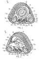
- a track system is generally designated by the reference numeral 10.
- the track system 10 is mounted on an axle (not shown) of an agricultural vehicle such as a tractor or combine.
- an agricultural vehicle such as a tractor or combine.
- track system 10 it is contemplated as being within the scope of the present invention for track system 10 to be mounted on other types of vehicles such as trucks, automobiles, and the like.
- Track system 10 includes a drive wheel 12 which is mountable to the axle of a vehicle for rotational movement therewith in order to drive a flexible track 15. As best seen in FIGURE 1 , in the preferred embodiment, it is intended to mount track system 10 to a vehicle having a planetary axle. However, it is contemplated to mount track system 10 to a bar axle or other type of axle without deviating from the scope of the present invention.
- drive wheel 12 includes a first set of circumferentially spaced attachment openings 18 therein which are aligned with corresponding openings formed in an attachment flange extending radially from the axle of the vehicle, as is conventional.
- Bolts extend through attachment openings 18 in drive wheel 12 and through corresponding openings in the attachment flange of the axle and are secured by corresponding nuts threaded on the ends thereof in order to interconnect the axle of the vehicle to drive wheel 12 so as to allow drive wheel 12 to rotate in unison with the axle of the vehicle.
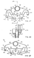
- drive wheel 12 includes an inner wall 20 and an outer wall 22 interconnected by a radially outer rim 24.
- Outer rim 24 includes a plurality of circumferentially spaced openings 26 therein for allowing debris which may accumulate on the inner surface 28 of flexible track 15 to pass therethrough.
- Outer rim 24 further includes an outer surface which forms lug-engagement surfaces 29 having a plurality of circumferentially spaced drive lugs 30 projecting radially therefrom. As hereinafter described, drive lugs 30 are intended to engage corresponding lugs 32 projecting inwardly from the inner surface 28 of flexible track 15 in order to drive flexible track 15.
- track system 10 further includes frame 34 of a uni-body construction.
- Frame 34 includes first and second side portions 36 and 38, respectively, which define a drive wheel receipt well 40 therebetween for receiving drive wheel 12.
- Side portions 36 and 38 of frame 34 are interconnected by front and rear end panels 42 and 44, respectively.
- Side portion 36 includes first and second upper panels 46 and 48, respectively, which extend laterally from outer surface 50 of generally tubular spindle hub 52 and a lower panel 53.
- Side panel 56 interconnects first sides 46a and 48a of upper panels 46 and 48, respectively,-and first side 53a of lower panel 53.
- Side panel 54 projects from second sides 46b and 48b of upper panels 46 and 48, respectively, and is joined to second side 53b of lower panel 53.
- a support member 60 extends between outer surface 54b of side panel 54 and lower surface 62 of lower panel 53 to add strength and stability to side panel 54 during operation of track system 10.
- support member 60 takes the form of a gusset, but other configurations are possible without deviating from the scope of the present invention.
- Side panel 54 includes leading and trailing apertures 64 and 66, respectively, therethrough for receiving corresponding leading and trailing bogie axles, respectively, as hereinafter described.
- Reinforcement elements 64a and 66a may be mounted on outer surface 54b of side panel 54 about corresponding apertures 64 and 66, respectively, to reinforce apertures 64 and 66 and prevent deformation of the same by the bogie axles received therein.
- Side portion 38 of frame 34 includes generally tubular, forward and rearward arms 70 and 72, respectively.
- Forward arm 70 includes a first end 74 which is joined to front end panel 42.
- rearward arm 72 includes a first end 76 joined to rear end panel 44.
- Second ends 78 and 80 of forward and rearward arms 70 and 72, respectively, are interconnected to the upper surface 82 of a generally horizontal base plate 84.
- Base plate 84 includes an inner edge 86 directed towards drive wheel receipt well 40 and an outer edge 88.
- Side panel 90 depends from inner edge 86 of base plate 84 and includes leading and trailing apertures 92 and 94, respectively, therethrough for receiving corresponding leading and trailing bogie axles, as hereinafter described.
- Leading aperture 92 in side panel 90 of side portion 38 is axially aligned with leading aperture 64 in side panel 54 of side portion 36.
- trailing aperture 94 in side panel 90 of side portion 38 is axially aligned with trailing aperture 66 in side panel 54 of side portion 36.
- Reinforcement elements 92a and 94a may be mounted on outer surface 90b of side panel 90 about corresponding apertures 92 and 94, respectively, to reinforce apertures 92 and 94 and prevent deformation of the same by the bogie axles received therein.
- Outer surface 90b of side panel 90 of side portion 38 is interconnected to the lower surface 98 of base plate 84 by a support structure 100 to add strength and stability to side panel 90.
- support member 100 takes the form of a gusset, but other configurations are possible without deviating from the scope of the present invention.
- a leading bogie axle 99 extends through leading aperture 64 in side panel 54 and through leading aperture 92 in side panel 90.
- Leading bogie wheels 101 are mounted on rims 103, FIGS 1-2 , in a conventional manner which, in turn, are mounted on corresponding ends of leading bogie axle 99 in a conventional manner for rotational movement therewith.
- the outer surfaces 10 1a of leading bogie wheels101 engage the inner surface 28 of flexible track 15.
- a trailing bogie axle 105 extends through trailing aperture66. in side panel 54 and through trailing aperture 94 in side panel 90.
- Trailing bogie wheels 107 are mounted on rims 109, FIGURES 1-2 , in a conventional manner which, in turn, are mounted on opposite ends of trailing bogie axle 105 in conventional manner for rotational movement therewith.
- the outer surfaces 107a of trailing bogie wheels 107 engage the inner surface 28 of flexible track 15.
- Inner surface 54a of side panel 54 of side portion 36 is interconnected to inner surface 90a by leading and trailing bogie axle shrouds 102 and 104, respectively.
- Leading bogie axle shroud 102 is generally arcuate in shape and has a first end positioned adjacent leading aperture 64 in side panel 54 of side portion 36 and a second opposite end 102b adjacent leading aperture 92 in side panel 90 of side portion 38 so as to partially surround leading bogie axle 99.
- First and second spaced mounting flanges 95 and 97 project from leading bogie axle shroud 102.
- Mounting flanges 95 and 97 include corresponding openings 95a and 97a, respectively, therein for reasons hereinafter described.
- Trailing bogie axle shroud 104 is arcuate in shape and includes a first end positioned adjacent trailing aperture 66 in side panel 54 of side portion 36 and a second end 104b positioned adjacent trailing aperture 94 in side panel 90 of side portion 38 so as to partially surround trailing bogie axle 105.
- Frame 34 further includes a trailing idler axle support arm 110 which extends between trailing bogie axle shroud 104 and rear end panel 44.
- Trailing idler axle support arm 110 includes a generally tubular trailing idler axle support 112 having an inner surface 114 for rotatably supporting trailing idler axle 116.
- Trailing idler wheels 117 are mounted on rims 118, FIGURES 1-2 , in a conventional manner which, in turn, are mounted on corresponding ends of trailing idler axle 116 in a conventional manner for rotational movement therewith.
- Trailing idler wheels 117 include radially outer surfaces 117a for engaging the inner surface 28 of flexible track 15.
- Frame 34 further includes a leading idler axle support arm 120 depending from front end panel 42.
- leading idler axle support arm 120 has a generally tubular terminal end 122 having an inner surface 124 defining a passageway 126 therethrough.
- Leading idler axle support 130 is pivotally mounted to leading idler support arm 120 by mounting pin 132 extending through passageway 126 in terminal end 122.
- Leading idler axle support 130 includes a leading idler axle passageway 134 for allowing leading idler axle 136 to pass therethrough.
- Leading idler axle 136 includes a notch 136a formed therein for allowing piston shaft 139 of cylinder 142 to extend therepast.
- leading idler axle 136 supports leading idler wheels 137 on opposite ends thereof.
- Leading idler wheels137 are mounted on rims138 which, in turn, are mounted on corresponding ends of leading idler axle 136 in a conventional manner for rotational movement therewith. It is contemplated to provide bearings 141 between rims 138 and corresponding ends of leading idler axle 136 to facilitate rotation of leading idler wheels 137 thereabout.
- Leading idler wheels 137 include a radially outer surface 137a for engaging the inner surface 28 of flexible track 15.
- Leading idler axle support 130 further includes a first and second piston mounting ears 140a and 140b depending therefrom.
- Each mounting ear 140a and 140b includes a corresponding aperture 142a and 142b, respectively, therethrough to accommodate piston shaft mounting pin 144.
- Apertures 142a and 142b in piston shaft mounting ears 140a and 140b, respectively, are axially aligned.
- Piston shaft mounting ears 140a and 140b define a piston receipt cavity 146 therebetween for receiving terminal end 148 of piston shaft 139.
- terminal end 148 of piston shaft 139 includes an opening 150 for receiving mounting pin 144 such that piston shaft 139 of cylinder 142 may pivot on mounting pin 144.
- piston shaft 139 includes a second opposite end 154 received within chamber 156 within cylinder housing 158 of cylinder 142.
- Cylinder housing 158 includes a first open end 159 for allowing piston shaft 139 to be inserted within chamber 156 and an opposite closed end 160.
- Inner surface 162 of cylinder housing 158 forms a slidable interface with the outer surface 164 of piston shaft 139.
- Closed end 160 of cylinder housing 158 includes a dog ear having an opening 166 passing therethrough. Closed end 160 of cylinder housing 158 is positioned between mounting flanges 95 and 97 such that opening 166 in closed end 160 is aligned with openings 95a and 97a in mounting flanges 95 and 97, respectively.
- Pin 168 extends through openings 95a and 97a in mounting flanges 95 and 97, respectively, and through opening 166 in closed end 160 of cylinder housing 158 so as to pivotally connect cylinder 142 to frame 34.
- chamber 156 within cylindrical housing158 communicates with input 169 of manifold 170 through conduit 172.
- conduit 172 extends through opening 174 in lower panel 53 of side portion 36 of frame 34 and through opening 176 in upper panel 48 of side portion 36 of frame 34.
- manifold 170 is mounted to upper surface 178 of upper panel 48.
- Manifold 170 includes a first output 180 operatively connected to the input 182 of low pressure cylinder 184 and a second output 186 operatively connected to the input 188 of high pressure cylinder 190.
- Seals 192 are provided between the outputs 180 and 186 of manifold 170 and the inputs 182 and 188 of cylinders 184 and 190, respectively, to maintain the integrity of the connections therebetween.
- Cylinder 184 includes an inner surface 194 defining a chamber 196 therein.
- a piston 198 is slidably received within chamber 196 so as to divide chamber 196 into a first portion 196a for receiving low pressure nitrogen gas therein and a second portion 196b which communicates with chamber 156 within cylinder housing 158 through manifold 170 and conduit 172.
- a generally tubular limiter member 200 is positioned within chamber 196.
- Limiter member 200 includes an outer surface 202 which engages the inner surface 194 of cylinder 184.
- Limiter member 200 limits movement of piston 198 such that piston 198 is slidable between a first position, FIGURE 6 , and a second position, FIGURES 7 and 8 .
- Cylinder 190 includes an inner surface 204 defining a chamber 206 therein.
- a piston 208 is slidably received within chamber 206 so as to divide chamber 206 into a first portion 206a for receiving a high pressure nitrogen gas therein and a second portion 206b which communicates with chamber 156 within cylinder housing 158 through manifold 170 and conduit 172. It is contemplated to provide a fluid within chamber 156 of cylinder housing 158, conduit 172, manifold 170, and second portions 196b and 206b of chambers 196 and 206, respectively, in cylinders 184 and 190, respectively.
- the amount of force necessary to insert piston shaft 139 a predetermined distance within chamber 156 of cylinder housing 158 gradually increases from an initial value A to an increased value A' as the low pressure nitrogen gas is compressed in first portion 196a of chamber 196 in cylinder 184 by piston 198 being urged from the first to the second position by the fluid.
- the amount of force necessary to further insert piston shaft 139 a second predetermined distance Y-X within chamber 156 of cylinder housing 158 gradually increases from an initial value B to an increased value B'. Since the nitrogen gas within cylinder 190 is under greater pressure than the nitrogen gas within cylinder 184, a substantially greater force is required for piston shaft 139 to travel the predetermined distance Y-X than the initial predetermined distance X.
- track system 10 is mounted to an axle of a vehicle through drive wheel 12 as heretofore described.
- the axle of the vehicle is rotated in a conventional manner through the vehicle by its engine and through a transmission which can vary the speeds and allow for forward and reverse rotation.
- Flexible track 15 of track apparatus 10 is positioned over drive wheel 12 such that lugs 32 projecting from the inner surface 28 of flexible track 15 are received between corresponding pairs of drive lugs 30 projecting from outer surface 29 of outer rim 24 of drive wheel 121.
- terminal end surface 32a of such lugs 32 engage outer surface 29 of outer rim 24 of drive wheel in order that lugs 32 are supported when driven by drive wheel 12, thereby minimizing the possible turisting and turning of lugs 32, and hence damage to lugs 32 during operation of track system 10.
- lugs 30 engage corresponding lugs 32 and drive flexible track 15 about drive wheel 12.
- successive drive lugs 30 engage subsequent lugs 32 extending from the inner surface 28 of flexible track 15 so as to drive flexible track 15 about drive wheel 12.
- lugs 32 pass therebetween.
- the radially outer surfaces 137a of leading idler wheels 137 engage the inner surface 28 of flexible track 15 and direct the lower length of flexible track 15 into contact with a supporting surface such as a farmer's field.
- lugs 3. 2 pass between the pairs of leading and trailing bogie wheels 101 and 107, respectively.
- the radially outer surfaces 10 1a and 107a of bogie wheels 101 and 107 engage the inner surface 28 of flexible track 15 along its lower length and insure contact of flexible track 15 with the supporting surface along the lower length of flexible track 15.
- lugs 32 on the inner surface 28 of flexible track 15 pass therebetween.
- the radially outer surfaces 117a of idler wheels 117 engage the inner surface 28 of flexible track 15 and guide flexible track 15 onto drive wheel 12 to form a continuous loop.
- trailing idler wheels 117 may function as leading idler wheels, and such that leading idler wheels 137 may function as trailing idler wheels as heretofore described.
- piston shaft 139 of cylinder 142 is provided. It is heretofore described, the nitrogen gas in the first portions 196a and 206a of chambers 196 and 206, respectively, of corresponding cylinders 184 and 190, respectively, urge corresponding pistons 198 and 208 towards the first position. As a result, the fluid in chamber 156 of cylinder housing 158 urges piston shaft 139 therefrom. Piston shaft 139, in turn, urges the outer surfaces 137a of leading idler wheels 137 into contact with the inner surface 28 of flexible track 15 through connection with leading idler axle support 130 so as to maintain proper tension on flexible track 15.
- the structure of track system 10 allows for deflection of the flexible track in response to obstructions or the like while maintaining the proper tension thereon. It can be appreciated that the tension on the flexible track may be adjusted by varying the pressure of the nitrogen gas in first portions 196a and 206a of chambers 196 and206, respectively, in corresponding cylinders 184 and 190, respectively, and/or by varying the position of limiter member 200.
Landscapes
- Engineering & Computer Science (AREA)
- Chemical & Material Sciences (AREA)
- Combustion & Propulsion (AREA)
- Transportation (AREA)
- Mechanical Engineering (AREA)
- Vehicle Body Suspensions (AREA)
- Arrangement Or Mounting Of Propulsion Units For Vehicles (AREA)
- Platform Screen Doors And Railroad Systems (AREA)
- Transmissions By Endless Flexible Members (AREA)
- Electrical Discharge Machining, Electrochemical Machining, And Combined Machining (AREA)
- Noodles (AREA)
- Body Structure For Vehicles (AREA)
- Arrangement And Driving Of Transmission Devices (AREA)
- Rolling Contact Bearings (AREA)
- Tires In General (AREA)
Claims (8)
- Spurvorrichtung (10), die auf einer drehbaren Achse eines Fahrzeugs angebracht ist, wobei die Spurvorrichtung aufweist:eine kontinuierliche flexible Spur bzw. Bahn (15) mit einer inneren Hauptoberfläche (28) und beabstandeten Spurvorsprüngen (32), die davon hervorragen, wobei jede Spurvorsprung (32) in einer Abschlussendoberfläche (32a) nach innen beabstandet von der inneren Hauptoberfläche abschließt, undein Antriebsrad (12), das auf der Achse angebracht ist, um die flexible Spur um die Achse anzutreiben, wobei das Antriebsrad eine zentrale Nabe (52) umfasst und einen sich radial erstreckenden Abschnitt mit inneren und äußeren Wänden, (20, 22), die sich radial von der zentralen Nabe zu einem äußeren Rand (24) erstrecken, der damit verbunden ist, wobei der äußere Rand (24) Vorsprungeingriffoberflächen (29) aufweist, wobei die Spurvorsprünge (32) in Vorsprung aufnehmenden Spalten aufgenommen sind, die zwischen entsprechenden Paaren von Antriebsvorsprüngen (30) gebildet sind, die von den Vorsprungeingriffoberflächen (29) des äußeren Rahmens (24) des Antriebsrads (12) vorspringen, dadurch gekennzeichnet, dass die axiale Breite der Vorsprungeingriffoberflächen (29) gleich der axialen Breite der Antriebsvorsprünge (30) ist, so dass die Abschlussendoberflächen (32a) der Spurvorsprünge (32) an die Vorsprungeingriffoberflächen (29) des äußeren Rands (24) des Antriebsrads angreifen, damit die Vorsprünge (32) gestützt sind, wenn diese durch das Antriebsrad angetrieben werden.
- Spurvorrichtung nach Anspruch 1, bei der das Antriebsrad frei von einer Seitenstruktur in Positionen ist, die lateral neben den Vorsprungeingriffsoberflächen und radial über der äußeren Kante sind, wobei die Spurvorsprünge (32) frei sind, ihre präzisen Positionen des Eingriffs mit den Vorsprungeingriffoberflächen einzustellen.
- Spurvorrichtung nach Anspruch 1 oder 2, bei der der äußere Rand eine Mehrzahl von beabstandeten Öffnungen (26) darin umfasst.
- Spurvorrichtung nach Anspruch 3, bei der die Mehrzahl von Öffnungen (26) in dem äußeren Rand des Antriebsrads umfänglich beabstandet um die zentrale Nabe sind.
- Spurvorrichtung nach Anspruch 3 oder 4, bei der das Antriebsrad eine Antriebsachse aufweist und wobei jede Vorsprungeingriffoberfläche (29) sich in einer axialen Richtung parallel zu der Antriebsachse erstreckt, so dass jede Vorsprungeingriffoberfläche einen Abschnitt eines Zylinders bildet.
- Spurvorrichtung nach einem der vorstehenden Ansprüche, die weiterhin aufweist:eine führende Laufachse (136), um drehbar ein führendes Laufrad (137) zu stützen, das an die flexible Spur angreift, undeinen Rahmen (34) einschließlich eines führenden Laufstützarms (120) mit einem Abschlussende, das einen Durchgang für ein drehbares Aufnehmen der führenden Laufachse dadurch definiert.
- Spurvorrichtung nach Anspruch 6, bei der der Rahmen (34) einen ersten und zweiten Seitenabschnitt (36, 38) umfasst, die eine Antriebsradaufnahmesenke (40) zwischen sich definieren, um das Antriebsrad (12) aufzunehmen.
- Spurvorrichtung nach einem der vorstehenden Ansprüche, bei der die Antriebsvorsprünge (30) des Antriebsrads umfänglich beabstandet um die zentrale Nabe sind.
Applications Claiming Priority (3)
| Application Number | Priority Date | Filing Date | Title |
|---|---|---|---|
| US09/627,862 US6543862B1 (en) | 2000-07-28 | 2000-07-28 | Drive wheel for track apparatus |
| US627862 | 2000-07-28 | ||
| EP01959281A EP1240070A4 (de) | 2000-07-28 | 2001-07-27 | Antriebsrad für ein gleiskettengerät |
Related Parent Applications (1)
| Application Number | Title | Priority Date | Filing Date |
|---|---|---|---|
| EP01959281A Division EP1240070A4 (de) | 2000-07-28 | 2001-07-27 | Antriebsrad für ein gleiskettengerät |
Publications (2)
| Publication Number | Publication Date |
|---|---|
| EP1493652A1 EP1493652A1 (de) | 2005-01-05 |
| EP1493652B1 true EP1493652B1 (de) | 2008-05-28 |
Family
ID=24516457
Family Applications (2)
| Application Number | Title | Priority Date | Filing Date |
|---|---|---|---|
| EP01959281A Withdrawn EP1240070A4 (de) | 2000-07-28 | 2001-07-27 | Antriebsrad für ein gleiskettengerät |
| EP04024199A Expired - Lifetime EP1493652B1 (de) | 2000-07-28 | 2001-07-27 | Gleiskettenvorrichtung |
Family Applications Before (1)
| Application Number | Title | Priority Date | Filing Date |
|---|---|---|---|
| EP01959281A Withdrawn EP1240070A4 (de) | 2000-07-28 | 2001-07-27 | Antriebsrad für ein gleiskettengerät |
Country Status (9)
| Country | Link |
|---|---|
| US (1) | US6543862B1 (de) |
| EP (2) | EP1240070A4 (de) |
| AT (1) | ATE396909T1 (de) |
| AU (1) | AU784457B2 (de) |
| CA (1) | CA2386204C (de) |
| DE (1) | DE60134284D1 (de) |
| ES (1) | ES2306946T3 (de) |
| GB (1) | GB2370820B (de) |
| WO (1) | WO2002010007A1 (de) |
Families Citing this family (32)
| Publication number | Priority date | Publication date | Assignee | Title |
|---|---|---|---|---|
| US6536854B2 (en) * | 2000-07-28 | 2003-03-25 | Agtracks, Inc. | Drive wheel for track apparatus |
| GB0113127D0 (en) * | 2001-05-30 | 2001-07-25 | Heard Stephen J | Drive wheel for rubber track system |
| US7077216B2 (en) * | 2003-10-21 | 2006-07-18 | Ati, Inc. | Earth scraper with track apparatus |
| WO2005047090A1 (en) * | 2003-11-11 | 2005-05-26 | Fargo Products, Llc | Track system for a ground engaging vehicle |
| US7156185B2 (en) * | 2003-12-08 | 2007-01-02 | Ati, Inc. | Soil stabilizer with track apparatus |
| US7255184B2 (en) * | 2004-01-02 | 2007-08-14 | Loegering Mfg, Inc. | Track assembly |
| GB2435865A (en) * | 2006-03-06 | 2007-09-12 | Stephen John Heard | Vehicle mountable crawler track assembly |
| WO2008073456A2 (en) | 2006-12-11 | 2008-06-19 | Loegering Mfg. Inc. | Apparatus for converting a wheeled vehicle to a tracked vehicle |
| US8794358B2 (en) | 2006-12-12 | 2014-08-05 | Loegering Mfg., Inc. | Conversion system for a wheeled vehicle |
| ITMN20070016A1 (it) * | 2007-04-20 | 2008-10-21 | Tidue S R L | Cingolatura di movimentazione di macchina operatrice su terreno |
| WO2009033052A1 (en) * | 2007-09-07 | 2009-03-12 | Loegering Mfg. Inc. | Apparatus for converting a wheeled vehicle to a tracked vehicle |
| USD587727S1 (en) * | 2007-10-15 | 2009-03-03 | Vermeer Manufacturing Company | Quad track trencher |
| US8245800B2 (en) | 2008-12-09 | 2012-08-21 | Vermeer Manufacturing Company | Apparatus for converting a wheeled vehicle to a tracked vehicle |
| US10266216B2 (en) | 2010-04-20 | 2019-04-23 | Denis Boivin | Track system having anti-diving flaps |
| US8776931B2 (en) | 2010-04-20 | 2014-07-15 | Denis Boivin | Track system for an all-wheel drive vehicle |
| US8857924B2 (en) | 2010-05-27 | 2014-10-14 | Ati, Inc. | Lugs of continuous rubber tracks for track vehicles |
| US8967737B2 (en) | 2010-06-30 | 2015-03-03 | Camoplast Solideal Inc. | Wheel of a track assembly of a tracked vehicle |
| US9505454B1 (en) | 2011-06-13 | 2016-11-29 | Camso Inc. | Track assembly for traction of an off-road vehicle |
| US8746815B2 (en) | 2011-07-28 | 2014-06-10 | Ati, Inc. | Track-module apparatus and open lightweight drive wheel therefor |
| US10427735B2 (en) | 2012-07-06 | 2019-10-01 | Mtd Products Inc | Drive sprocket for a tracked utility vehicle |
| EP2879942B1 (de) | 2012-07-30 | 2017-05-17 | CNH Industrial Italia S.P.A. | Fahrwerksystem für ein kettenarbeitsfahrzeug |
| CA3133490A1 (en) | 2013-09-13 | 2015-03-19 | Mtd Products Inc | Drive sprocket for a tracked vehicle |
| US9884662B2 (en) | 2013-09-13 | 2018-02-06 | Mtd Products Inc | Suspension and lock-out systems for a partially tracked vehicle |
| US9580121B2 (en) | 2014-03-13 | 2017-02-28 | Ati, Inc. | Vehicle track assembly having tapered wheels |
| EP3303102B1 (de) | 2015-05-29 | 2023-08-23 | MTD products Inc | Nutzfahrzeug |
| US10875591B2 (en) | 2015-08-04 | 2020-12-29 | Camso Inc. | Track system for traction of an agricultural vehicle travelling on fields and roads |
| US9988108B2 (en) | 2015-10-23 | 2018-06-05 | Camso Manufacturing Italy S.R.L. | Track system for traction of a vehicle |
| US11511818B2 (en) | 2017-09-05 | 2022-11-29 | Mtd Products Inc | Track drive |
| CN108238121A (zh) * | 2018-03-28 | 2018-07-03 | 黑龙江重兴机械设备有限公司 | 一种大型联合收获机装配的四边形半履带装置 |
| CN108313149A (zh) * | 2018-03-28 | 2018-07-24 | 黑龙江重兴机械设备有限公司 | 一种橡胶四边形半履带行走装置的架体 |
| RU188792U1 (ru) * | 2018-11-08 | 2019-04-23 | Михаил Юрьевич Головнов | Ведущее колесо гусеничного привода |
| USD1054458S1 (en) | 2022-01-13 | 2024-12-17 | Soucy International Inc. | Track assembly |
Citations (1)
| Publication number | Priority date | Publication date | Assignee | Title |
|---|---|---|---|---|
| JPH11129946A (ja) * | 1997-11-04 | 1999-05-18 | Toyota Autom Loom Works Ltd | クローラ及び車両 |
Family Cites Families (23)
| Publication number | Priority date | Publication date | Assignee | Title |
|---|---|---|---|---|
| US36284A (en) | 1862-08-26 | Improvement in hats | ||
| US1852197A (en) * | 1924-12-17 | 1932-04-05 | Thew Shovel Co | Traction mechanism |
| US1853308A (en) * | 1930-04-12 | 1932-04-12 | Walter G Humphreys | Sprocket wheel |
| US1922357A (en) * | 1932-06-16 | 1933-08-15 | Marion Steam Shovel Co | Tumbler for crawling traction mechanism |
| US2592541A (en) * | 1949-06-14 | 1952-04-15 | George W Curtis | Self-cleaning endless track |
| US3359044A (en) * | 1966-01-17 | 1967-12-19 | Caterpillar Tractor Co | Tractor track shoe with replaceable wear plate |
| US3880478A (en) * | 1974-01-07 | 1975-04-29 | Case Co J I | Crawler chain sprocket with relief openings |
| US3888132A (en) * | 1974-05-15 | 1975-06-10 | Gates Rubber Co | Positive drive belt and system |
| US4175796A (en) * | 1978-05-26 | 1979-11-27 | Caterpillar Tractor Co. | Track-type vehicle wheel cleaning apparatus |
| US4241956A (en) * | 1978-06-12 | 1980-12-30 | Caterpillar Tractor Co. | Track assembly for crawler-type vehicles |
| US4616883A (en) * | 1984-05-04 | 1986-10-14 | Edwards, Harper, Mcnew And Company | Endless drive system |
| US4861120A (en) * | 1987-05-14 | 1989-08-29 | Edwards, Harper, Mcnew & Company | Modular endless track drive system and methods of making, installing and repairing same |
| US5005921A (en) * | 1987-05-14 | 1991-04-09 | Edwards, Harper, Mcnew & Company | Endless track drive system |
| JPH05501529A (ja) * | 1989-11-13 | 1993-03-25 | ワレイン・プロプライエタリー・リミテッド | 確実に駆動されるエラストマの無限軌道で動く作業車 |
| US5240084A (en) | 1992-03-26 | 1993-08-31 | Christianson Peter J | Converter assembly for converting a drive-wheel tractor into a track-driven tractor |
| US5452949A (en) | 1993-12-13 | 1995-09-26 | Kelderman; Gary L. | Track system for vehicles |
| US5829848A (en) | 1995-06-23 | 1998-11-03 | Agtracks, Inc. | Track suspension apparatus for vehicles of various types |
| JPH09240529A (ja) | 1996-03-04 | 1997-09-16 | Kubota Corp | クローラ式走行装置 |
| JPH09240526A (ja) * | 1996-03-11 | 1997-09-16 | Toyota Autom Loom Works Ltd | 三角クローラ及びクローラ車 |
| US5774521A (en) * | 1996-07-08 | 1998-06-30 | Cedars-Sinai Medical Center | Regularization technique for densitometric correction |
| JPH10181645A (ja) | 1996-12-25 | 1998-07-07 | Toyota Autom Loom Works Ltd | クローラ、クローラ車及び自動車 |
| DE19701436B4 (de) | 1997-01-17 | 2006-08-03 | Claas Selbstfahrende Erntemaschinen Gmbh | Selbstfahrende Arbeitsmaschine |
| US6074025A (en) * | 1998-07-10 | 2000-06-13 | Agtracks, Inc. | Track apparatus incorporating cantilever mounted wheels |
-
2000
- 2000-07-28 US US09/627,862 patent/US6543862B1/en not_active Expired - Lifetime
-
2001
- 2001-07-27 AU AU80854/01A patent/AU784457B2/en not_active Ceased
- 2001-07-27 CA CA002386204A patent/CA2386204C/en not_active Expired - Fee Related
- 2001-07-27 DE DE60134284T patent/DE60134284D1/de not_active Expired - Lifetime
- 2001-07-27 GB GB0208517A patent/GB2370820B/en not_active Expired - Fee Related
- 2001-07-27 WO PCT/US2001/023729 patent/WO2002010007A1/en not_active Ceased
- 2001-07-27 ES ES04024199T patent/ES2306946T3/es not_active Expired - Lifetime
- 2001-07-27 AT AT04024199T patent/ATE396909T1/de not_active IP Right Cessation
- 2001-07-27 EP EP01959281A patent/EP1240070A4/de not_active Withdrawn
- 2001-07-27 EP EP04024199A patent/EP1493652B1/de not_active Expired - Lifetime
Patent Citations (1)
| Publication number | Priority date | Publication date | Assignee | Title |
|---|---|---|---|---|
| JPH11129946A (ja) * | 1997-11-04 | 1999-05-18 | Toyota Autom Loom Works Ltd | クローラ及び車両 |
Non-Patent Citations (1)
| Title |
|---|
| PATENT ABSTRACTS OF JAPAN vol. 1999, no. 10 31 August 1999 (1999-08-31) * |
Also Published As
| Publication number | Publication date |
|---|---|
| WO2002010007A1 (en) | 2002-02-07 |
| GB0208517D0 (en) | 2002-05-22 |
| AU784457B2 (en) | 2006-04-06 |
| ES2306946T3 (es) | 2008-11-16 |
| EP1240070A4 (de) | 2002-10-23 |
| ATE396909T1 (de) | 2008-06-15 |
| DE60134284D1 (de) | 2008-07-10 |
| EP1493652A1 (de) | 2005-01-05 |
| AU8085401A (en) | 2002-02-13 |
| EP1240070A1 (de) | 2002-09-18 |
| CA2386204C (en) | 2008-09-23 |
| US6543862B1 (en) | 2003-04-08 |
| CA2386204A1 (en) | 2002-02-07 |
| GB2370820B (en) | 2003-01-22 |
| GB2370820A (en) | 2002-07-10 |
Similar Documents
| Publication | Publication Date | Title |
|---|---|---|
| EP1493652B1 (de) | Gleiskettenvorrichtung | |
| CA2386392C (en) | Frame for track apparatus | |
| CA2386205C (en) | Tensioning device for track apparatus | |
| US6536854B2 (en) | Drive wheel for track apparatus | |
| US7077216B2 (en) | Earth scraper with track apparatus | |
| WO2000002767A1 (en) | Track apparatus incorporating non-pneumatic wheels | |
| HK1127886B (en) | Frame for track apparatus | |
| GB2384469A (en) | Tensioning device for track apparatus | |
| US20220388584A1 (en) | Support structure for connecting a plurality of support wheel assemblies to a frame member of a track system and track system having the same | |
| EP4587318A1 (de) | Gleisanlage für fahrzeuge mit doppelausrichtsystem | |
| JPH0755665B2 (ja) | セミクローラ型乗用作業機 |
Legal Events
| Date | Code | Title | Description |
|---|---|---|---|
| PUAI | Public reference made under article 153(3) epc to a published international application that has entered the european phase |
Free format text: ORIGINAL CODE: 0009012 |
|
| 17P | Request for examination filed |
Effective date: 20041011 |
|
| AC | Divisional application: reference to earlier application |
Ref document number: 1240070 Country of ref document: EP Kind code of ref document: P |
|
| AK | Designated contracting states |
Kind code of ref document: A1 Designated state(s): AT BE CH CY DE DK ES FI FR GB GR IE IT LI LU MC NL PT SE TR |
|
| AKX | Designation fees paid |
Designated state(s): AT BE CH CY DE DK ES FI FR GB GR IE IT LI LU MC NL PT SE TR |
|
| RAP1 | Party data changed (applicant data changed or rights of an application transferred) |
Owner name: ATI, INC. |
|
| TPAC | Observations filed by third parties |
Free format text: ORIGINAL CODE: EPIDOSNTIPA |
|
| 17Q | First examination report despatched |
Effective date: 20051121 |
|
| 17Q | First examination report despatched |
Effective date: 20051121 |
|
| TPAC | Observations filed by third parties |
Free format text: ORIGINAL CODE: EPIDOSNTIPA |
|
| GRAP | Despatch of communication of intention to grant a patent |
Free format text: ORIGINAL CODE: EPIDOSNIGR1 |
|
| GRAS | Grant fee paid |
Free format text: ORIGINAL CODE: EPIDOSNIGR3 |
|
| GRAA | (expected) grant |
Free format text: ORIGINAL CODE: 0009210 |
|
| AC | Divisional application: reference to earlier application |
Ref document number: 1240070 Country of ref document: EP Kind code of ref document: P |
|
| AK | Designated contracting states |
Kind code of ref document: B1 Designated state(s): AT BE CH CY DE DK ES FI FR GB GR IE IT LI LU MC NL PT SE TR |
|
| REG | Reference to a national code |
Ref country code: GB Ref legal event code: FG4D |
|
| REG | Reference to a national code |
Ref country code: CH Ref legal event code: EP |
|
| REF | Corresponds to: |
Ref document number: 60134284 Country of ref document: DE Date of ref document: 20080710 Kind code of ref document: P |
|
| REG | Reference to a national code |
Ref country code: IE Ref legal event code: FG4D |
|
| REG | Reference to a national code |
Ref country code: SE Ref legal event code: TRGR |
|
| PG25 | Lapsed in a contracting state [announced via postgrant information from national office to epo] |
Ref country code: FI Free format text: LAPSE BECAUSE OF FAILURE TO SUBMIT A TRANSLATION OF THE DESCRIPTION OR TO PAY THE FEE WITHIN THE PRESCRIBED TIME-LIMIT Effective date: 20080528 |
|
| REG | Reference to a national code |
Ref country code: ES Ref legal event code: FG2A Ref document number: 2306946 Country of ref document: ES Kind code of ref document: T3 |
|
| PG25 | Lapsed in a contracting state [announced via postgrant information from national office to epo] |
Ref country code: NL Free format text: LAPSE BECAUSE OF FAILURE TO SUBMIT A TRANSLATION OF THE DESCRIPTION OR TO PAY THE FEE WITHIN THE PRESCRIBED TIME-LIMIT Effective date: 20080528 Ref country code: AT Free format text: LAPSE BECAUSE OF FAILURE TO SUBMIT A TRANSLATION OF THE DESCRIPTION OR TO PAY THE FEE WITHIN THE PRESCRIBED TIME-LIMIT Effective date: 20080528 |
|
| NLV1 | Nl: lapsed or annulled due to failure to fulfill the requirements of art. 29p and 29m of the patents act | ||
| PG25 | Lapsed in a contracting state [announced via postgrant information from national office to epo] |
Ref country code: DK Free format text: LAPSE BECAUSE OF FAILURE TO SUBMIT A TRANSLATION OF THE DESCRIPTION OR TO PAY THE FEE WITHIN THE PRESCRIBED TIME-LIMIT Effective date: 20080528 Ref country code: PT Free format text: LAPSE BECAUSE OF FAILURE TO SUBMIT A TRANSLATION OF THE DESCRIPTION OR TO PAY THE FEE WITHIN THE PRESCRIBED TIME-LIMIT Effective date: 20081028 |
|
| PG25 | Lapsed in a contracting state [announced via postgrant information from national office to epo] |
Ref country code: BE Free format text: LAPSE BECAUSE OF FAILURE TO SUBMIT A TRANSLATION OF THE DESCRIPTION OR TO PAY THE FEE WITHIN THE PRESCRIBED TIME-LIMIT Effective date: 20080528 |
|
| REG | Reference to a national code |
Ref country code: CH Ref legal event code: PL |
|
| PG25 | Lapsed in a contracting state [announced via postgrant information from national office to epo] |
Ref country code: MC Free format text: LAPSE BECAUSE OF NON-PAYMENT OF DUE FEES Effective date: 20080731 |
|
| PLBE | No opposition filed within time limit |
Free format text: ORIGINAL CODE: 0009261 |
|
| STAA | Information on the status of an ep patent application or granted ep patent |
Free format text: STATUS: NO OPPOSITION FILED WITHIN TIME LIMIT |
|
| REG | Reference to a national code |
Ref country code: IE Ref legal event code: MM4A |
|
| 26N | No opposition filed |
Effective date: 20090303 |
|
| PG25 | Lapsed in a contracting state [announced via postgrant information from national office to epo] |
Ref country code: CH Free format text: LAPSE BECAUSE OF NON-PAYMENT OF DUE FEES Effective date: 20080731 Ref country code: LI Free format text: LAPSE BECAUSE OF NON-PAYMENT OF DUE FEES Effective date: 20080731 |
|
| PG25 | Lapsed in a contracting state [announced via postgrant information from national office to epo] |
Ref country code: IE Free format text: LAPSE BECAUSE OF NON-PAYMENT OF DUE FEES Effective date: 20080727 |
|
| PG25 | Lapsed in a contracting state [announced via postgrant information from national office to epo] |
Ref country code: CY Free format text: LAPSE BECAUSE OF FAILURE TO SUBMIT A TRANSLATION OF THE DESCRIPTION OR TO PAY THE FEE WITHIN THE PRESCRIBED TIME-LIMIT Effective date: 20080528 Ref country code: LU Free format text: LAPSE BECAUSE OF NON-PAYMENT OF DUE FEES Effective date: 20080727 |
|
| PG25 | Lapsed in a contracting state [announced via postgrant information from national office to epo] |
Ref country code: TR Free format text: LAPSE BECAUSE OF FAILURE TO SUBMIT A TRANSLATION OF THE DESCRIPTION OR TO PAY THE FEE WITHIN THE PRESCRIBED TIME-LIMIT Effective date: 20080528 |
|
| PG25 | Lapsed in a contracting state [announced via postgrant information from national office to epo] |
Ref country code: GR Free format text: LAPSE BECAUSE OF FAILURE TO SUBMIT A TRANSLATION OF THE DESCRIPTION OR TO PAY THE FEE WITHIN THE PRESCRIBED TIME-LIMIT Effective date: 20080829 |
|
| REG | Reference to a national code |
Ref country code: FR Ref legal event code: PLFP Year of fee payment: 16 |
|
| PGFP | Annual fee paid to national office [announced via postgrant information from national office to epo] |
Ref country code: IT Payment date: 20160721 Year of fee payment: 16 Ref country code: GB Payment date: 20160727 Year of fee payment: 16 Ref country code: DE Payment date: 20160726 Year of fee payment: 16 |
|
| PGFP | Annual fee paid to national office [announced via postgrant information from national office to epo] |
Ref country code: FR Payment date: 20160729 Year of fee payment: 16 Ref country code: SE Payment date: 20160726 Year of fee payment: 16 |
|
| PGFP | Annual fee paid to national office [announced via postgrant information from national office to epo] |
Ref country code: ES Payment date: 20160726 Year of fee payment: 16 |
|
| REG | Reference to a national code |
Ref country code: DE Ref legal event code: R119 Ref document number: 60134284 Country of ref document: DE |
|
| REG | Reference to a national code |
Ref country code: SE Ref legal event code: EUG |
|
| GBPC | Gb: european patent ceased through non-payment of renewal fee |
Effective date: 20170727 |
|
| REG | Reference to a national code |
Ref country code: FR Ref legal event code: ST Effective date: 20180330 |
|
| PG25 | Lapsed in a contracting state [announced via postgrant information from national office to epo] |
Ref country code: DE Free format text: LAPSE BECAUSE OF NON-PAYMENT OF DUE FEES Effective date: 20180201 Ref country code: SE Free format text: LAPSE BECAUSE OF NON-PAYMENT OF DUE FEES Effective date: 20170728 Ref country code: GB Free format text: LAPSE BECAUSE OF NON-PAYMENT OF DUE FEES Effective date: 20170727 |
|
| PG25 | Lapsed in a contracting state [announced via postgrant information from national office to epo] |
Ref country code: FR Free format text: LAPSE BECAUSE OF NON-PAYMENT OF DUE FEES Effective date: 20170731 |
|
| PG25 | Lapsed in a contracting state [announced via postgrant information from national office to epo] |
Ref country code: IT Free format text: LAPSE BECAUSE OF NON-PAYMENT OF DUE FEES Effective date: 20170727 |
|
| REG | Reference to a national code |
Ref country code: ES Ref legal event code: FD2A Effective date: 20181029 |
|
| PG25 | Lapsed in a contracting state [announced via postgrant information from national office to epo] |
Ref country code: ES Free format text: LAPSE BECAUSE OF NON-PAYMENT OF DUE FEES Effective date: 20170728 |