EP1493700B1 - Procédé et dispositif pour l'accumulation de feuilles de papier - Google Patents
Procédé et dispositif pour l'accumulation de feuilles de papier Download PDFInfo
- Publication number
- EP1493700B1 EP1493700B1 EP04014778A EP04014778A EP1493700B1 EP 1493700 B1 EP1493700 B1 EP 1493700B1 EP 04014778 A EP04014778 A EP 04014778A EP 04014778 A EP04014778 A EP 04014778A EP 1493700 B1 EP1493700 B1 EP 1493700B1
- Authority
- EP
- European Patent Office
- Prior art keywords
- sheets
- sheet
- accumulating
- accumulation
- accumulator
- Prior art date
- Legal status (The legal status is an assumption and is not a legal conclusion. Google has not performed a legal analysis and makes no representation as to the accuracy of the status listed.)
- Expired - Lifetime
Links
Images


Classifications
-
- B—PERFORMING OPERATIONS; TRANSPORTING
- B65—CONVEYING; PACKING; STORING; HANDLING THIN OR FILAMENTARY MATERIAL
- B65H—HANDLING THIN OR FILAMENTARY MATERIAL, e.g. SHEETS, WEBS, CABLES
- B65H29/00—Delivering or advancing articles from machines; Advancing articles to or into piles
- B65H29/12—Delivering or advancing articles from machines; Advancing articles to or into piles by means of the nip between two, or between two sets of, moving tapes or bands or rollers
- B65H29/14—Delivering or advancing articles from machines; Advancing articles to or into piles by means of the nip between two, or between two sets of, moving tapes or bands or rollers and introducing into a pile
-
- B—PERFORMING OPERATIONS; TRANSPORTING
- B65—CONVEYING; PACKING; STORING; HANDLING THIN OR FILAMENTARY MATERIAL
- B65H—HANDLING THIN OR FILAMENTARY MATERIAL, e.g. SHEETS, WEBS, CABLES
- B65H31/00—Pile receivers
- B65H31/30—Arrangements for removing completed piles
- B65H31/3027—Arrangements for removing completed piles by the nip between moving belts or rollers
-
- B—PERFORMING OPERATIONS; TRANSPORTING
- B65—CONVEYING; PACKING; STORING; HANDLING THIN OR FILAMENTARY MATERIAL
- B65H—HANDLING THIN OR FILAMENTARY MATERIAL, e.g. SHEETS, WEBS, CABLES
- B65H39/00—Associating, collating, or gathering articles or webs
- B65H39/10—Associating articles from a single source, to form, e.g. a writing-pad
-
- B—PERFORMING OPERATIONS; TRANSPORTING
- B65—CONVEYING; PACKING; STORING; HANDLING THIN OR FILAMENTARY MATERIAL
- B65H—HANDLING THIN OR FILAMENTARY MATERIAL, e.g. SHEETS, WEBS, CABLES
- B65H45/00—Folding thin material
- B65H45/12—Folding articles or webs with application of pressure to define or form crease lines
- B65H45/14—Buckling folders
- B65H45/142—Pocket-type folders
-
- B—PERFORMING OPERATIONS; TRANSPORTING
- B65—CONVEYING; PACKING; STORING; HANDLING THIN OR FILAMENTARY MATERIAL
- B65H—HANDLING THIN OR FILAMENTARY MATERIAL, e.g. SHEETS, WEBS, CABLES
- B65H9/00—Registering, e.g. orientating, articles; Devices therefor
- B65H9/004—Deskewing sheet by abutting against a stop, i.e. producing a buckling of the sheet
-
- B—PERFORMING OPERATIONS; TRANSPORTING
- B65—CONVEYING; PACKING; STORING; HANDLING THIN OR FILAMENTARY MATERIAL
- B65H—HANDLING THIN OR FILAMENTARY MATERIAL, e.g. SHEETS, WEBS, CABLES
- B65H2301/00—Handling processes for sheets or webs
- B65H2301/40—Type of handling process
- B65H2301/42—Piling, depiling, handling piles
- B65H2301/421—Forming a pile
- B65H2301/4213—Forming a pile of a limited number of articles, e.g. buffering, forming bundles
-
- B—PERFORMING OPERATIONS; TRANSPORTING
- B65—CONVEYING; PACKING; STORING; HANDLING THIN OR FILAMENTARY MATERIAL
- B65H—HANDLING THIN OR FILAMENTARY MATERIAL, e.g. SHEETS, WEBS, CABLES
- B65H2301/00—Handling processes for sheets or webs
- B65H2301/40—Type of handling process
- B65H2301/42—Piling, depiling, handling piles
- B65H2301/421—Forming a pile
- B65H2301/4219—Forming a pile forming a pile in which articles are offset from each other, e.g. forming stepped pile
- B65H2301/42194—Forming a pile forming a pile in which articles are offset from each other, e.g. forming stepped pile forming a pile in which articles are offset from each other in the delivery direction
-
- B—PERFORMING OPERATIONS; TRANSPORTING
- B65—CONVEYING; PACKING; STORING; HANDLING THIN OR FILAMENTARY MATERIAL
- B65H—HANDLING THIN OR FILAMENTARY MATERIAL, e.g. SHEETS, WEBS, CABLES
- B65H2301/00—Handling processes for sheets or webs
- B65H2301/40—Type of handling process
- B65H2301/42—Piling, depiling, handling piles
- B65H2301/422—Handling piles, sets or stacks of articles
- B65H2301/4226—Delivering, advancing piles
- B65H2301/42262—Delivering, advancing piles by acting on surface of outermost articles of the pile, e.g. in nip between pair of belts or rollers
-
- B—PERFORMING OPERATIONS; TRANSPORTING
- B65—CONVEYING; PACKING; STORING; HANDLING THIN OR FILAMENTARY MATERIAL
- B65H—HANDLING THIN OR FILAMENTARY MATERIAL, e.g. SHEETS, WEBS, CABLES
- B65H2301/00—Handling processes for sheets or webs
- B65H2301/50—Auxiliary process performed during handling process
- B65H2301/51—Modifying a characteristic of handled material
- B65H2301/512—Changing form of handled material
- B65H2301/5121—Bending, buckling, curling, bringing a curvature
- B65H2301/51212—Bending, buckling, curling, bringing a curvature perpendicularly to the direction of displacement of handled material, e.g. forming a loop
- B65H2301/512125—Bending, buckling, curling, bringing a curvature perpendicularly to the direction of displacement of handled material, e.g. forming a loop by abutting against a stop
-
- B—PERFORMING OPERATIONS; TRANSPORTING
- B65—CONVEYING; PACKING; STORING; HANDLING THIN OR FILAMENTARY MATERIAL
- B65H—HANDLING THIN OR FILAMENTARY MATERIAL, e.g. SHEETS, WEBS, CABLES
- B65H2404/00—Parts for transporting or guiding the handled material
- B65H2404/70—Other elements in edge contact with handled material, e.g. registering, orientating, guiding devices
- B65H2404/72—Stops, gauge pins, e.g. stationary
- B65H2404/723—Stops, gauge pins, e.g. stationary formed of forwarding means
- B65H2404/7231—Stops, gauge pins, e.g. stationary formed of forwarding means by nip rollers in standby
-
- B—PERFORMING OPERATIONS; TRANSPORTING
- B65—CONVEYING; PACKING; STORING; HANDLING THIN OR FILAMENTARY MATERIAL
- B65H—HANDLING THIN OR FILAMENTARY MATERIAL, e.g. SHEETS, WEBS, CABLES
- B65H2801/00—Application field
- B65H2801/66—Envelope filling machines
Definitions
- the present invention relates to an inserter input system and method for generating accumulations of sheets of printed material to be inserted into envelopes.
- Such an inserter input system cuts and processes a continuous web of material into individual sheets. The individual sheets belonging to a single mail piece are accumulated together and are then further processed together downstream.
- Inserter systems such as those applicable for use with the present invention, are typically used by organizations such as banks, insurance companies and utility companies for producing a large volume of specific mailings where the contents of each mail item are directed to a particular addressee. Also, other organizations, such as direct mailers, use inserts for producing a large volume of generic mailings where the contents of each mail item are substantially identical for each addressee. Examples of such inserter systems are the 8 series, 9 series, and APSTM inserter systems available from Pitney Bowes Inc. of Stamford, Connecticut, USA.
- the typical inserter system resembles a manufacturing assembly line. Sheets and other raw materials (other sheets, enclosures, and envelopes) enter the inserter system as inputs. Then, a plurality of different modules or workstations in the inserter system work cooperatively to process the sheets until a finished mail piece is produced. The exact configuration of each inserter system depends upon the needs of each particular customer or installation.
- inserter systems prepare mail pieces by gathering collations of documents on a conveyor. The collations are then transported on the conveyor to an insertion station where they are automatically stuffed into envelopes. After being stuffed with the collations, the envelopes are removed from the insertion station for further processing. Such further processing may include automated closing and sealing the envelope flap, weighing the envelope, applying postage to the envelope, and finally sorting and stacking the envelopes.
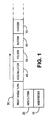
- Fig. 1 The input stages of a typical inserter system are depicted in Fig. 1.
- rolls or stacks of continuous printed documents called a "web” are fed into the inserter system by a web feeder 10 .
- the continuous web must be separated into individual document pages. This separation is typically carried out by a web cutter 20 that cuts the continuous web into individual document pages. Downstream of the web cutter 20 , a right angle turn 30 may be used to reorient the documents, and/or to meet the inserter user's floor space requirements.
- the separated documents must subsequently be grouped into collations corresponding to the multi-page documents to be included in individual mail pieces. This gathering of related document pages occurs in the accumulator module 40 where individual pages are stacked on top of one another.
- the control system for the inserter senses markings on the individual pages to determine what pages are to be collated together in the accumulator module 40 .
- mail pieces may include varying numbers of pages to be accumulated.
- the phone bill for a person who lives by himself may be much shorter than another phone bill representing calls made by a large family.
- the accumulator 40 is capable of generating accumulations having varying numbers of sheets in accordance with data for the particular mail piece.
- a folder 50 Downstream of the accumulator 40 , a folder 50 typically folds the accumulation of documents so that they will fit in the desired envelopes. To allow the same inserter system to be used with different sized mailings, the folder 50 can typically be adjusted to make different sized folds on different sized paper. As a result, an inserter system must be capable of handling different lengths of accumulated and folded documents.
- a buffer transport 60 transports and stores accumulated and folded documents in series in preparation for transferring the documents to the synchronous inserter chassis 70 .
- a sheet accumulating device comprising a first accumulator including: an input transport; an accumulating receptacle downstream of the input transport and receiving sheets from the input transport, the accumulating receptacle having an upper guide and a lower guide forming an accumulating channel, the accumulating channel being substantially horizontal; accumulation dump rollers at a downstream end of the accumulating receptacle, the dump rollers controlled to act as a stop during sheet accumulation, and to transport completed accumulations from the sheet accumulating device, the dump rollers positioned downstream from the input transport a distance less than the length of sheets to be accumulated; and a trap arrangement at an upstream end of the accumulating receptacle positioned beneath the input transport and below a level of the accumulating channel for receiving trailing portions of accumulated sheets stopped at the dump rollers and that buckle into the trap arrangement from the input transport; wherein at least one of the lower or the upper guide comprises a continuously rotating belt to urge accumulating sheets against the
- a method for accumulating and transporting sheets comprising: transporting a sheet to an accumulation receptacle; stopping the sheet in the accumulation receptacle with accumulation dump rollers in a stopped condition; buckling a rear portion of transported sheets into a trap arrangement when a lead edge of the sheet stops at the dump rollers; and urging accumulating sheets in the accumulating receptacle against the dump rollers with an urging arrangement that provides a continuous urging force while slipping over the surface of transported sheets.
- An accumulator device in accordance with one described embodiment has a downward angled input transport. This downward angle, in connection with the further elements, helps to ensure proper overlapping of sheets. Downstream of the input transport an accumulating receptacle receives sheets.
- the accumulating receptacle has an upper guide and a lower guide forming a horizontal accumulating channel.
- accumulation dump rollers act as a stop during sheet accumulation, and as a transport for removing completed accumulations from the sheet accumulating device.
- the dump rollers are positioned downstream from the input transport a distance less than the length of sheets to be accumulated. Because of this short distance and because of the angle of the input rollers, the rear portion of the sheet will tend to buckle downward.
- a trap arrangement below the input rollers receives the downward buckled rear portion of the sheet.
- the downward positioning of the rear portion helps to ensure that subsequent sheets will lay on top of the previous sheet.
- the upper guide of the accumulating channel comprises a continuously rotating belt to urge accumulating sheets against the dump rollers.
- a positive air device may be used to assist in the buckling of the rear portion of the sheets.
- the positive air device may also be used as a substitute for the angled orientation of the input transport is assisting the buckling action into the trap arrangement.
- Accumulators in accordance with the following description may be used in parallel to provide greater efficiency.
- the multiple accumulators allow one to be used to receive sheets while the other is busy discharging a completed accumulation.
- a sensor senses the arrival of sheets in the accumulating receptacle.
- the dump rollers perform a small predetermined incremental displacement thereby slightly shingling the sheets. Such incrementing allows the dump rollers to continuously maintain positive control over the entire accumulation, and is useful for handling large collations.
- dump rollers can discharge the slightly shingled accumulation without uncontrolled slippage that might otherwise result from a thick stack.
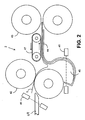
- FIG. 2 A preferred embodiment for an accumulator 2 in accordance with the present invention is depicted in Fig. 2.
- a sheet 1 is transported into the accumulator 2 between input rollers 42 .
- sensor 41 detects the position of sheet 1 as it enters the accumulator 2 .
- Sensor 41 is preferably an optical sensor that detects the lead and trail edges of sheets 1 .
- Sensor 41 may also be used to scan a code on sheet 1 in order to obtain information about the mail piece to which the sheet belongs. Based on information in a scanned code, the system may determine how many sheets to accumulate in accumulator 2 to form a collation belonging to a single mail piece.
- input rollers 42 are positioned to deliver the sheet 1 at a downward angle. As the sheet 1 is passed through rollers 42 , its leading edge will come into contact with lower guide 44 and be guided in a horizontal direction. A horizontal accumulating channel is formed between guides 44 and 47 . At the end of the horizontal accumulating channel, a lead edge of the sheet encounters accumulation dump rollers 43 . In a first embodiment, when the lead edge of a sheet arrives at dump rollers 43 , the rollers are stopped. In this embodiment, the dump rollers 43 remain at a stopped position until a complete collation is formed, and then the complete collation is transported by dump rollers 43 to a next downstream location.
- Dump rollers 43 are preferably driven from both sides.
- the upper and lower shafts are geared together to provide a positive drive to accumulated sheets. This preferred embodiment assists in transport of thicker sheet collations.
- the diameter of the rollers for dump rollers 43 is preferably about two inches (about 5 cm). This diameter is sufficient to assist in the transport of thicker packets of sheets.
- Dump rollers 43 are preferably comprised of a urethane material, soft enough to prevent damage to the lead edge of sheet 1 and to prevent significant bounce-back upon impact of the lead edge. Dump rollers 43 are also designed to be soft enough to absorb the impact of sheets traveling at high velocities, without damaging them. While softness is preferred for minimizing impact, the dump rollers 43 should also be durable enough that the parts do not wear out too quickly. Accordingly, a preferred urethane surface having a hardness of approximately 35-45 on an A-scale durometer should be used on the surface of dump rollers 43 . A hardness of 40 on an A-scale durometer is most preferred.
- Dump rollers 43 are positioned downstream of input rollers 42 by a distance less than the length of sheet 1 to be accumulated. Therefore, when the lead edge of sheet 1 is stopped by the dump roller 43 , input rollers 42 are still transporting the tail end of the sheet 1 . Since sheet 1 cannot move forward in the accumulating channel, the downward angle of rollers 42 causes the sheet to buckle into a trap arrangement 45 .
- the trap arrangement 45 assists in the dissipation of the energy of the sheets traveling at high velocities. When a leading portion of the sheets hits the dump rollers 43 energy from the rear portion of the sheet can be dissipated in the trap 45 .
- Trap arrangement 45 is preferably an upstream extension of lower guide 44 .
- the trap arrangement 45 is substantially below the input rollers 42 , and below the plane of the accumulating channel. As the trail end of sheet 1 passes through the input rollers 42 it is guided down into the trap arrangement 45 . Thus, when the sheet 1 is at rest in the accumulator 2 a leading portion is supported in the accumulating channel, and a trailing portion is supported in the trap arrangement 45 .
- a sensor 46 detects the successful arrival of a trail portion of a document into the trap arrangement. Sensor 46 may also detect when a sheet is not laying flat in the trap arrangement 45 .
- the upper guide 47 is a continuously rotating belt that urges accumulated sheets in a downstream direction.
- a rotating belt helps to guarantee that the sheet reaches the dump rollers 43 .
- the guide belt provides drive for the incoming sheets that might otherwise be pinched between the upper guide 47 and the collation.
- the belt of upper guide 47 provides a transporting force while the sheet is moving the same speed as the belt. However, because the static friction is greater than the dynamic friction, as soon as the sheet is stopped by the dump rollers, the belt 47 will slip over the surface of the paper.
- the belt or belts may be comprised of plastic o-rings mounted on moving rollers or, preferably, a flat belt. With the belts used in upper guide 47 , the use of the dump rollers 43 as a stopping arrangement is made feasible where high sheet speeds may have previously prevented that arrangement from being used.
- a positive air source 49 can be used to blow air on the sheet 1 to assist in the buckling action of the sheet into the trap 45 .
- air is blown onto a trailing portion of sheet 1 after the leading portion of the sheet has passed.
- sensor 41 may be used to detect the passage of the trail edge of sheet 1 , and may be used to trigger the positive air pressure from air source 49 when the trail edge passes through sensor 41 . It will also be understood that some form of negative air pressure from below the sheet may also be used to assist in buckling.
- the preferred embodiment using air source 49 may allow the downward angle of input rollers 42 to be eliminated altogether.
- the input rollers 42 , the accumulation channel, and the dump rollers 43 may all be in the same transport plane, and avoid inaccuracies that may result from redirecting the transport path of the sheets.
- accumulator 2 and accumulator 3 may be used in a parallel arrangement.
- sheets may be fed into the parallel accumulator 2 .
- a diverter mechanism 4 will direct sheets belonging to the same mail piece to one of the two parallel accumulators 2 or 3 .
- the diverter 4 changes the paper path to begin the next accumulation in the alternate accumulator.
- the diverter 4 receives sheets serially from upstream transport rollers 7 .
- Diverter 4 is preferably a flipper gate that alternates between paper paths leading to accumulators 2 and 3 .
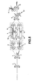
- FIG. 4 A further preferred embodiment of the present invention is depicted in Fig. 4.
- This embodiment addresses a problem resulting from the sudden acceleration of the dump rollers 43 to remove completed accumulations from the accumulator 2 .
- Execution of the aggressive acceleration on thick collations may cause the sheets to become unaligned and not reliably translate together as a uniform packet. Such failure to reliably translate together may result in jams, poor fold quality, and mail piece integrity problems.
- dump rollers 43 may not be large enough that the lead edge of the stack is sufficiently positioned between the rollers such that it can be reliably accelerated.
- dump rollers 43 may be driven on only one side. As a result, being driven on one side, excessive slippage may result, as one side of the collation is translated more quickly than the other.
- pinch rollers In the past, one method of addressing the problem of discharging thick collations has been to use "pinch rollers" that movably close upon a completed collation and then provide a motive force to discharge the collation from the accumulator. As seen in U.S. Patent 5,178,379, pinch rollers remain out of the way when the collation is being formed, and are not used for stopping or registering the collation.
- the preferred embodiment of the present invention utilizes a technique that eliminates the need for additional moving parts to handle thicker collations.
- the dump roller 43 rotates by a small increment to ingest a portion of the newly arrived sheet between the rollers 43 .
- the incremental rotation of the dump rollers 43 may be triggered by sensing of the lead edge arriving at the dump rollers.
- sensor 41 may be used to trigger the incrementing of the dump rollers 43 when the tail edge of sheet 1 is entering rollers 42 .
- the lead edge will have arrived at the dump rollers 43 .
- slightly shingled accumulations will not require folding. However, for other accumulations the slight shingling may be a consideration with respect to a folder 50 .
- a conventional folder 50 if a shingled collation is input, the edges of the resulting folded documents will not be aligned with one another. Given the relatively small amount of shingling displacement needed to implement the preferred embodiment, the slightly shingled documents may be folded and further processed without concern. However, if the specifications for fitting a folded collation into an envelope are so tight that the slightly shingled folded collations will not fit, then an intermediary mechanism for registering the collations is needed.
- Registration mechanisms 12 and 13 may be of any conventional registration/accumulation technology.
- the registration mechanisms are comprised of transport belts 14 , with a reciprocating stop device 15 .
- a slightly shingled collation 5 enters the registration mechanism 12 , transported between belts 14 .
- the collation 5 then is registered against a stopping surface of the stop device 15 . After the collation 5 has been registered it, the stopping surface is lowered and the collation may be transported on to the next processing station.
- the present invention may also be useful for providing "reverse accumulation" of sheets.
- a first sheet to arrive in the accumulator becomes the bottom sheet in the collation as consecutive sheets are stacked on top.
- the first sheet be the top sheet and that subsequent sheets be added to the bottom of a collation. This adding of sheets to the bottom of an accumulation is referred to as "reverse accumulation.”
- Reverse accumulation is achieved by flipping the accumulator described above around its horizontal axis so that it is oriented up-side down. In this way, a first sheet will remain on top in the accumulating channel, as subsequent sheets are added underneath.
Landscapes
- Engineering & Computer Science (AREA)
- Mechanical Engineering (AREA)
- Delivering By Means Of Belts And Rollers (AREA)
- Pile Receivers (AREA)
Claims (15)
- Dispositif pour l'accumulation de feuilles de papier comprenant un premier accumulateur (2) comprenant :un transporteur d'entrée (42) ;un réceptacle d'accumulation (44, 47 ; 44, 48) en aval du transporteur d'entrée (42) qui reçoit les feuilles (1) du transporteur d'entrée, le réceptacle d'accumulation ayant un rail supérieur (47) et un rail inférieur (44) qui forment un canal d'accumulation, le canal d'accumulation étant essentiellement horizontal ;des cylindres d'éjection des accumulations (43) à une extrémité en aval du réceptacle d'accumulation, les cylindres d'éjection étant contrôlés pour servir d'arrêt lors de l'accumulation de feuilles, et pour transporter les accumulations terminées à partir du dispositif d'accumulation de feuilles (44, 47 ; 44, 48), les cylindres d'éjection (43) étant disposés en aval du transporteur d'entrée à une distance inférieure à la longueur des feuilles à accumuler ; etun dispositif collecteur (45) à une extrémité en amont du réceptacle d'accumulation disposé après le transporteur d'entrée (42) et sous le niveau du canal d'accumulation pour recevoir les parties à l'arrière des feuilles accumulées arrêtées aux cylindres d'éjection et qui se gondolent dans le dispositif collecteur à partir du transporteur d'entrée ;dans lequel au moins un des rails, inférieur (44) ou supérieurs (47 ; 48) comprend une bande sans fin pour contraindre les feuilles à s'accumuler contre les cylindres d'éjection (43).
- Dispositif selon la revendication 1, dans lequel les cylindres d'éjection d'accumulation (43) sont constitués d'uréthane d'une dureté comprise dans la plage de 35 à 45 sur un duromètre A.
- Dispositif selon la revendication 1 comprenant en outre une source de pression d'air (49) disposée de façon proximale par rapport au dispositif collecteur pour faire entrer les parties arrière des feuilles dans le dispositif collecteur.
- Dispositif selon la revendication 1 comprenant en outre un deuxième accumulateur (2, 3) en parallèle du premier accumulateur et dans lequel un mécanisme de déviation (4) en amont du premier et du deuxième accumulateur dévie alternativement les paquets de feuilles vers le deuxième accumulateur pendant que le premier accumulateur décharge une première accumulation terminée, et vers le premier accumulateur pendant que le deuxième accumulateur décharge une deuxième accumulation terminée.
- Dispositif selon la revendication 4 comprenant en outre un transporteur de sortie en aval du premier et du deuxième accumulateur et dans lequel les produits du premier et du deuxième accumulateur qui sont parallèles se rejoignent sur une seule voie de transport.
- Dispositif d'accumulation de feuilles selon la revendication 1, dans lequel le transporteur d'entrée forme un angle orienté vers le bas par rapport au réceptacle d'accumulation, afin de faciliter le gondolage des feuilles dans le dispositif collecteur.
- Dispositif d'accumulation de feuilles selon la revendication 3, comprenant en outre un capteur (41) capable de détecter la position d'une feuille, la source de pression d'air (49) étant mise en fonctionnement en fonction de la position captée de la feuille.
- Dispositif d'accumulation de feuilles selon la revendication 1, dans lequel l'orientation du dispositif est placée tête en bas afin de créer un dispositif d'accumulation inversée.
- Procédé pour l'accumulation et le transport de feuilles, le procédé comprenant les étapes consistant à :transporter une feuille vers un réceptacle d'accumulation (44, 47 ; 44, 48) ;arrêter la feuille dans le réceptacle d'accumulation (44, 47 ; 44, 48) avec les cylindres d'éjection d'accumulation (43) en position d'arrêt ;gondoler la partie arrière des feuilles transportées dans un dispositif collecteur lorsque le bord avant est arrêté au niveau des cylindres d'éjection ; etcontraindre les feuilles à entrer dans le réceptacle d'accumulation contre les cylindres d'éjection au moyen d'un dispositif de contrainte qui applique une force de contrainte continue en glissant sur la surface des feuilles transportées.
- Procédé selon la revendication 9, dans lequel l'étape de gondolage implique en outre de faire souffler de l'air en direction du sol pour faire entrer la partie arrière des feuilles dans le dispositif collecteur.
- Procédé selon la revendication 9, dans lequel l'étape consistant à transporter la feuille vers le réceptacle d'accumulation implique de transporter la feuille sur un plan transporteur d'entrée formant un angle orienté vers le bas.
- Procédé selon l'une quelconque des revendications 9 à 11, comprenant en outre les étapes consistant à :détecter l'arrivée d'une feuille dans le réceptacle d'accumulation (44, 47 ; 44, 48) ;déplacer les cylindres d'éjection (43) dans une mesure réduite prédéterminée progressive lorsque l'arrivée d'une feuille est détectée, décalant ainsi légèrement les feuilles ;répéter les étapes précédentes pour une série de feuilles constituant une accumulation complète ; etdécharger l'accumulation terminée de feuilles légèrement décalées des cylindres d'éjection (43).
- Procédé selon la revendication 12, dans lequel le déplacement prédéterminé progressif est inférieur à 0,025 cm (0,010 inches).
- Procédé selon l'une quelconque des revendications 9 à 13, dans lequel avant l'accumulation des feuilles est prévue une déviation des feuilles vers l'une des deux voies d'accumulation au moins, où les paquets de feuilles sont déviés vers un deuxième accumulateur pendant que le premier accumulateur décharge un premier bloc d'accumulation terminé, et les feuilles sont déviées vers le premier accumulateur pendant que le deuxième accumulateur décharge une deuxième accumulation terminée.
- Procédé selon la revendication 14 comprenant en outre l'étape consistant à réunir les accumulations terminées des voies d'accumulation parallèles dans une seule voie de transport.
Priority Applications (1)
| Application Number | Priority Date | Filing Date | Title |
|---|---|---|---|
| EP06008777A EP1683751A3 (fr) | 2003-06-30 | 2004-06-24 | Procédé et dispositif pour l'accumulation de feuilles de papier |
Applications Claiming Priority (2)
| Application Number | Priority Date | Filing Date | Title |
|---|---|---|---|
| US611167 | 2000-07-06 | ||
| US10/611,167 US20050017438A1 (en) | 2003-06-30 | 2003-06-30 | Apparatus and method for accumulating sheets |
Related Child Applications (1)
| Application Number | Title | Priority Date | Filing Date |
|---|---|---|---|
| EP06008777A Division EP1683751A3 (fr) | 2003-06-30 | 2004-06-24 | Procédé et dispositif pour l'accumulation de feuilles de papier |
Publications (3)
| Publication Number | Publication Date |
|---|---|
| EP1493700A2 EP1493700A2 (fr) | 2005-01-05 |
| EP1493700A3 EP1493700A3 (fr) | 2005-03-09 |
| EP1493700B1 true EP1493700B1 (fr) | 2006-11-22 |
Family
ID=33435428
Family Applications (2)
| Application Number | Title | Priority Date | Filing Date |
|---|---|---|---|
| EP04014778A Expired - Lifetime EP1493700B1 (fr) | 2003-06-30 | 2004-06-24 | Procédé et dispositif pour l'accumulation de feuilles de papier |
| EP06008777A Withdrawn EP1683751A3 (fr) | 2003-06-30 | 2004-06-24 | Procédé et dispositif pour l'accumulation de feuilles de papier |
Family Applications After (1)
| Application Number | Title | Priority Date | Filing Date |
|---|---|---|---|
| EP06008777A Withdrawn EP1683751A3 (fr) | 2003-06-30 | 2004-06-24 | Procédé et dispositif pour l'accumulation de feuilles de papier |
Country Status (4)
| Country | Link |
|---|---|
| US (1) | US20050017438A1 (fr) |
| EP (2) | EP1493700B1 (fr) |
| CA (1) | CA2472870C (fr) |
| DE (1) | DE602004003299T2 (fr) |
Families Citing this family (5)
| Publication number | Priority date | Publication date | Assignee | Title |
|---|---|---|---|---|
| NL1032054C2 (nl) * | 2006-06-23 | 2007-12-27 | Neopost Technologies Sa | Werkwijze en bufferstation voor het bufferen van documenten. |
| US8342505B2 (en) * | 2006-10-18 | 2013-01-01 | Pitney Bowes Inc. | Bottom placement sheet accumulator device and method for an inserter system |
| US7866661B2 (en) * | 2007-08-29 | 2011-01-11 | Pitney Bowes Inc. | Sheet/page buffer for sheet handling apparatus |
| US20100042252A1 (en) * | 2008-08-13 | 2010-02-18 | Xerox Corporation | Disk type apparatus and corresponding methods |
| ITBO20110515A1 (it) * | 2011-09-09 | 2013-03-10 | C M C Srl | Buffer dinamico per sistema di imbustamento in continuo |
Family Cites Families (26)
| Publication number | Priority date | Publication date | Assignee | Title |
|---|---|---|---|---|
| US4346881A (en) * | 1979-04-12 | 1982-08-31 | Lenox Machine Company, Inc. | Method of and means for handling paper sheets to be stacked |
| US4598901A (en) * | 1984-10-24 | 1986-07-08 | Marquip, Inc. | Shingling and stacking of conveyed sheet material with pre-shingling control of sheet feed |
| US5039082A (en) * | 1986-04-04 | 1991-08-13 | Littleton Industrial Consultants, Inc. | Double slow down pinless and gripperless delivery system |
| EP0303276B1 (fr) * | 1987-08-12 | 1994-11-30 | Canon Kabushiki Kaisha | Appareil pour convoyer des feuilles et procédé pour convoyer des feuilles |
| US5305995A (en) * | 1989-12-18 | 1994-04-26 | Canon Kabushiki Kaisha | Sheet feeding apparatus for re-feeding a sheet without smearing |
| US5083769A (en) * | 1990-05-04 | 1992-01-28 | Pitney Bowes Inc. | Dual collating machine |
| US5178379A (en) * | 1991-07-23 | 1993-01-12 | Pitney Bowes Inc. | Sheet collator with alignment apparatus |
| US5356263A (en) * | 1992-12-16 | 1994-10-18 | Pitney Bowes Inc. | Buckle accumulator and method for accumulating sheets |
| JP3347384B2 (ja) * | 1993-02-08 | 2002-11-20 | キヤノン株式会社 | 画像形成装置 |
| US5289251A (en) * | 1993-05-19 | 1994-02-22 | Xerox Corporation | Trail edge buckling sheet buffering system |
| US5445368A (en) * | 1993-10-27 | 1995-08-29 | Pitney Bowes Inc. | Apparatus and method for forming collations of two different size documents |
| US5494276A (en) * | 1994-01-03 | 1996-02-27 | Bell & Howell Company | Method and apparatus for shingling documents |
| JPH07309476A (ja) * | 1994-05-16 | 1995-11-28 | Fuji Xerox Co Ltd | 用紙搬送装置 |
| US5435534A (en) * | 1994-07-11 | 1995-07-25 | Pitney Bowes Inc. | Method for accumulating, folding and subsetting collation |
| TW341955U (en) * | 1994-09-30 | 1998-10-01 | Mita Industrial Co Ltd | Device for conveying sheet members |
| US5543909A (en) * | 1995-04-03 | 1996-08-06 | Xerox Corporation | Two step, large latitude, stalled roll registration system |
| US5734566A (en) * | 1995-08-25 | 1998-03-31 | Pitney Bowes Inc. | Method and apparatus for keeping a matched document inserter system in synchronization |
| US5775690A (en) * | 1996-04-01 | 1998-07-07 | Xerox Corporation | Two step optimized stalled roll registration and deskew |
| US6120019A (en) * | 1998-09-30 | 2000-09-19 | Pitney Bowes Inc. | Corrugated input feed for a buckle accumulator |
| US6105957A (en) * | 1998-09-30 | 2000-08-22 | Pitney Bowes Inc. | Buckle accumulator having selectively activateable sheet deflector |
| JP3738946B2 (ja) * | 1999-03-24 | 2006-01-25 | コニカミノルタビジネステクノロジーズ株式会社 | 用紙カール矯正装置 |
| US6273419B1 (en) * | 1999-05-12 | 2001-08-14 | Pitney Bowes Inc. | Method and device for sheet collation |
| WO2002016243A2 (fr) * | 2000-08-24 | 2002-02-28 | Moore North America, Inc. | Massicot pour bande continue d'alimentation |
| US20020140162A1 (en) * | 2001-02-23 | 2002-10-03 | Thomas Gasser | Stacker |
| US6644657B2 (en) * | 2001-10-25 | 2003-11-11 | Pitney Bowes Inc. | Accumulator having power ramp |
| US6826445B2 (en) * | 2002-02-25 | 2004-11-30 | Pitney Bowes Inc. | Method and apparatus for inserting checks into a bank statement mail piece |
-
2003
- 2003-06-30 US US10/611,167 patent/US20050017438A1/en not_active Abandoned
-
2004
- 2004-06-24 EP EP04014778A patent/EP1493700B1/fr not_active Expired - Lifetime
- 2004-06-24 DE DE602004003299T patent/DE602004003299T2/de not_active Expired - Lifetime
- 2004-06-24 EP EP06008777A patent/EP1683751A3/fr not_active Withdrawn
- 2004-06-29 CA CA002472870A patent/CA2472870C/fr not_active Expired - Fee Related
Also Published As
| Publication number | Publication date |
|---|---|
| CA2472870A1 (fr) | 2004-12-30 |
| EP1493700A3 (fr) | 2005-03-09 |
| US20050017438A1 (en) | 2005-01-27 |
| EP1683751A3 (fr) | 2006-10-18 |
| EP1493700A2 (fr) | 2005-01-05 |
| DE602004003299T2 (de) | 2007-06-28 |
| DE602004003299D1 (de) | 2007-01-04 |
| EP1683751A2 (fr) | 2006-07-26 |
| CA2472870C (fr) | 2007-10-23 |
Similar Documents
| Publication | Publication Date | Title |
|---|---|---|
| EP0926085B1 (fr) | Double appareil de séparation de documents pour un système de traitement de courrier | |
| EP0455494A2 (fr) | Machine de collationnement double | |
| EP1461279B1 (fr) | Accumulateur a rampe de puissance | |
| EP1016549B1 (fr) | Systeme d'insertion | |
| US7021184B2 (en) | System and method for providing sheets to an inserter system using a rotary cutter | |
| US8540227B2 (en) | Accumulating apparatus for discrete paper or film objects and related methods | |
| US6386537B1 (en) | Sheet accumulator with diverting mechanisms | |
| US5876029A (en) | Feeder assembly apparatus | |
| US6102391A (en) | Right angle transfer apparatus | |
| EP1053963B1 (fr) | Sytème et procédé pour fournir des lots d'accumulation de documents à un système d'insertion | |
| EP1108563B1 (fr) | Méthode d'amenée d'enveloppes à un dispositif d'insertion | |
| EP1634838A1 (fr) | Machine pour accumuler des feuilles | |
| US5924265A (en) | Vacuum deck stopping mechanism | |
| US5911668A (en) | Vacuum envelope drive | |
| EP1493700B1 (fr) | Procédé et dispositif pour l'accumulation de feuilles de papier | |
| US6164640A (en) | Apparatus for directionally reorienting sheets | |
| US20020140162A1 (en) | Stacker | |
| US7427059B2 (en) | Paper handling system materials exit path arrangement | |
| EP1577242B1 (fr) | Système et procédé pour fournir des feuilles à un système d'insertion utilisant un dispositif de coupe à haute vitesse et une rotation à angle droit | |
| EP1795473B1 (fr) | Module de transfert à débit élevé pour tourner à angle droit | |
| US6776406B2 (en) | Feeder and separator for separating and moving sheets from a stack of sheets | |
| EP1334935B1 (fr) | Dispositif de manipulation de document avec mécanisme d'introduction dynamique et méthode correspondante | |
| US5685531A (en) | Process for accumulating unfolded paper sheets and collating with folded sheets | |
| CA2558631A1 (fr) | Appareil et methode pour accumuler les feuilles | |
| US7591454B2 (en) | Paper handling system material feed path arrangement |
Legal Events
| Date | Code | Title | Description |
|---|---|---|---|
| PUAI | Public reference made under article 153(3) epc to a published international application that has entered the european phase |
Free format text: ORIGINAL CODE: 0009012 |
|
| AK | Designated contracting states |
Kind code of ref document: A2 Designated state(s): AT BE BG CH CY CZ DE DK EE ES FI FR GB GR HU IE IT LI LU MC NL PL PT RO SE SI SK TR |
|
| AX | Request for extension of the european patent |
Extension state: AL HR LT LV MK |
|
| PUAL | Search report despatched |
Free format text: ORIGINAL CODE: 0009013 |
|
| AK | Designated contracting states |
Kind code of ref document: A3 Designated state(s): AT BE BG CH CY CZ DE DK EE ES FI FR GB GR HU IE IT LI LU MC NL PL PT RO SE SI SK TR |
|
| AX | Request for extension of the european patent |
Extension state: AL HR LT LV MK |
|
| 17P | Request for examination filed |
Effective date: 20050831 |
|
| AKX | Designation fees paid |
Designated state(s): DE FR GB |
|
| RAP1 | Party data changed (applicant data changed or rights of an application transferred) |
Owner name: PITNEY BOWES, INC. |
|
| GRAP | Despatch of communication of intention to grant a patent |
Free format text: ORIGINAL CODE: EPIDOSNIGR1 |
|
| GRAS | Grant fee paid |
Free format text: ORIGINAL CODE: EPIDOSNIGR3 |
|
| GRAA | (expected) grant |
Free format text: ORIGINAL CODE: 0009210 |
|
| AK | Designated contracting states |
Kind code of ref document: B1 Designated state(s): DE FR GB |
|
| REG | Reference to a national code |
Ref country code: GB Ref legal event code: FG4D |
|
| REF | Corresponds to: |
Ref document number: 602004003299 Country of ref document: DE Date of ref document: 20070104 Kind code of ref document: P |
|
| ET | Fr: translation filed | ||
| PLBE | No opposition filed within time limit |
Free format text: ORIGINAL CODE: 0009261 |
|
| 26N | No opposition filed |
Effective date: 20070823 |
|
| PGFP | Annual fee paid to national office [announced via postgrant information from national office to epo] |
Ref country code: FR Payment date: 20110629 Year of fee payment: 8 |
|
| REG | Reference to a national code |
Ref country code: FR Ref legal event code: ST Effective date: 20130228 |
|
| PG25 | Lapsed in a contracting state [announced via postgrant information from national office to epo] |
Ref country code: FR Free format text: LAPSE BECAUSE OF NON-PAYMENT OF DUE FEES Effective date: 20120702 |
|
| PGFP | Annual fee paid to national office [announced via postgrant information from national office to epo] |
Ref country code: GB Payment date: 20160627 Year of fee payment: 13 |
|
| PGFP | Annual fee paid to national office [announced via postgrant information from national office to epo] |
Ref country code: DE Payment date: 20160628 Year of fee payment: 13 |
|
| REG | Reference to a national code |
Ref country code: DE Ref legal event code: R119 Ref document number: 602004003299 Country of ref document: DE |
|
| GBPC | Gb: european patent ceased through non-payment of renewal fee |
Effective date: 20170624 |
|
| PG25 | Lapsed in a contracting state [announced via postgrant information from national office to epo] |
Ref country code: GB Free format text: LAPSE BECAUSE OF NON-PAYMENT OF DUE FEES Effective date: 20170624 Ref country code: DE Free format text: LAPSE BECAUSE OF NON-PAYMENT OF DUE FEES Effective date: 20180103 |