EP1493923A2 - Compresseur à plateau en biais - Google Patents
Compresseur à plateau en biais Download PDFInfo
- Publication number
- EP1493923A2 EP1493923A2 EP04015486A EP04015486A EP1493923A2 EP 1493923 A2 EP1493923 A2 EP 1493923A2 EP 04015486 A EP04015486 A EP 04015486A EP 04015486 A EP04015486 A EP 04015486A EP 1493923 A2 EP1493923 A2 EP 1493923A2
- Authority
- EP
- European Patent Office
- Prior art keywords
- suction
- valve
- passage
- compression chamber
- chamber
- Prior art date
- Legal status (The legal status is an assumption and is not a legal conclusion. Google has not performed a legal analysis and makes no representation as to the accuracy of the status listed.)
- Withdrawn
Links
Images


Classifications
-
- F—MECHANICAL ENGINEERING; LIGHTING; HEATING; WEAPONS; BLASTING
- F04—POSITIVE - DISPLACEMENT MACHINES FOR LIQUIDS; PUMPS FOR LIQUIDS OR ELASTIC FLUIDS
- F04B—POSITIVE-DISPLACEMENT MACHINES FOR LIQUIDS; PUMPS
- F04B27/00—Multi-cylinder pumps specially adapted for elastic fluids and characterised by number or arrangement of cylinders
- F04B27/08—Multi-cylinder pumps specially adapted for elastic fluids and characterised by number or arrangement of cylinders having cylinders coaxial with, or parallel or inclined to, main shaft axis
- F04B27/10—Multi-cylinder pumps specially adapted for elastic fluids and characterised by number or arrangement of cylinders having cylinders coaxial with, or parallel or inclined to, main shaft axis having stationary cylinders
- F04B27/1009—Distribution members
- F04B27/1018—Cylindrical distribution members
-
- F—MECHANICAL ENGINEERING; LIGHTING; HEATING; WEAPONS; BLASTING
- F04—POSITIVE - DISPLACEMENT MACHINES FOR LIQUIDS; PUMPS FOR LIQUIDS OR ELASTIC FLUIDS
- F04B—POSITIVE-DISPLACEMENT MACHINES FOR LIQUIDS; PUMPS
- F04B27/00—Multi-cylinder pumps specially adapted for elastic fluids and characterised by number or arrangement of cylinders
- F04B27/08—Multi-cylinder pumps specially adapted for elastic fluids and characterised by number or arrangement of cylinders having cylinders coaxial with, or parallel or inclined to, main shaft axis
- F04B27/0873—Component parts, e.g. sealings; Manufacturing or assembly thereof
- F04B27/0878—Pistons
-
- F—MECHANICAL ENGINEERING; LIGHTING; HEATING; WEAPONS; BLASTING
- F04—POSITIVE - DISPLACEMENT MACHINES FOR LIQUIDS; PUMPS FOR LIQUIDS OR ELASTIC FLUIDS
- F04B—POSITIVE-DISPLACEMENT MACHINES FOR LIQUIDS; PUMPS
- F04B27/00—Multi-cylinder pumps specially adapted for elastic fluids and characterised by number or arrangement of cylinders
- F04B27/08—Multi-cylinder pumps specially adapted for elastic fluids and characterised by number or arrangement of cylinders having cylinders coaxial with, or parallel or inclined to, main shaft axis
- F04B27/10—Multi-cylinder pumps specially adapted for elastic fluids and characterised by number or arrangement of cylinders having cylinders coaxial with, or parallel or inclined to, main shaft axis having stationary cylinders
- F04B27/1036—Component parts, details, e.g. sealings, lubrication
- F04B27/1045—Cylinders
-
- F—MECHANICAL ENGINEERING; LIGHTING; HEATING; WEAPONS; BLASTING
- F04—POSITIVE - DISPLACEMENT MACHINES FOR LIQUIDS; PUMPS FOR LIQUIDS OR ELASTIC FLUIDS
- F04B—POSITIVE-DISPLACEMENT MACHINES FOR LIQUIDS; PUMPS
- F04B49/00—Control, e.g. of pump delivery, or pump pressure of, or safety measures for, machines, pumps, or pumping installations, not otherwise provided for, or of interest apart from, groups F04B1/00 - F04B47/00
- F04B49/22—Control, e.g. of pump delivery, or pump pressure of, or safety measures for, machines, pumps, or pumping installations, not otherwise provided for, or of interest apart from, groups F04B1/00 - F04B47/00 by means of valves
- F04B49/225—Control, e.g. of pump delivery, or pump pressure of, or safety measures for, machines, pumps, or pumping installations, not otherwise provided for, or of interest apart from, groups F04B1/00 - F04B47/00 by means of valves with throttling valves or valves varying the pump inlet opening or the outlet opening
-
- F—MECHANICAL ENGINEERING; LIGHTING; HEATING; WEAPONS; BLASTING
- F04—POSITIVE - DISPLACEMENT MACHINES FOR LIQUIDS; PUMPS FOR LIQUIDS OR ELASTIC FLUIDS
- F04B—POSITIVE-DISPLACEMENT MACHINES FOR LIQUIDS; PUMPS
- F04B53/00—Component parts, details or accessories not provided for in, or of interest apart from, groups F04B1/00 - F04B23/00 or F04B39/00 - F04B47/00
- F04B53/10—Valves; Arrangement of valves
-
- F—MECHANICAL ENGINEERING; LIGHTING; HEATING; WEAPONS; BLASTING
- F16—ENGINEERING ELEMENTS AND UNITS; GENERAL MEASURES FOR PRODUCING AND MAINTAINING EFFECTIVE FUNCTIONING OF MACHINES OR INSTALLATIONS; THERMAL INSULATION IN GENERAL
- F16K—VALVES; TAPS; COCKS; ACTUATING-FLOATS; DEVICES FOR VENTING OR AERATING
- F16K15/00—Check valves
- F16K15/02—Check valves with guided rigid valve members
-
- F—MECHANICAL ENGINEERING; LIGHTING; HEATING; WEAPONS; BLASTING
- F16—ENGINEERING ELEMENTS AND UNITS; GENERAL MEASURES FOR PRODUCING AND MAINTAINING EFFECTIVE FUNCTIONING OF MACHINES OR INSTALLATIONS; THERMAL INSULATION IN GENERAL
- F16K—VALVES; TAPS; COCKS; ACTUATING-FLOATS; DEVICES FOR VENTING OR AERATING
- F16K15/00—Check valves
- F16K15/14—Check valves with flexible valve members
-
- F—MECHANICAL ENGINEERING; LIGHTING; HEATING; WEAPONS; BLASTING
- F25—REFRIGERATION OR COOLING; COMBINED HEATING AND REFRIGERATION SYSTEMS; HEAT PUMP SYSTEMS; MANUFACTURE OR STORAGE OF ICE; LIQUEFACTION SOLIDIFICATION OF GASES
- F25B—REFRIGERATION MACHINES, PLANTS OR SYSTEMS; COMBINED HEATING AND REFRIGERATION SYSTEMS; HEAT PUMP SYSTEMS
- F25B31/00—Compressor arrangements
- F25B31/02—Compressor arrangements of motor-compressor units
- F25B31/023—Compressor arrangements of motor-compressor units with compressor of reciprocating-piston type
-
- F—MECHANICAL ENGINEERING; LIGHTING; HEATING; WEAPONS; BLASTING
- F05—INDEXING SCHEMES RELATING TO ENGINES OR PUMPS IN VARIOUS SUBCLASSES OF CLASSES F01-F04
- F05B—INDEXING SCHEME RELATING TO WIND, SPRING, WEIGHT, INERTIA OR LIKE MOTORS, TO MACHINES OR ENGINES FOR LIQUIDS COVERED BY SUBCLASSES F03B, F03D AND F03G
- F05B2210/00—Working fluid
- F05B2210/10—Kind or type
- F05B2210/12—Kind or type gaseous, i.e. compressible
-
- F—MECHANICAL ENGINEERING; LIGHTING; HEATING; WEAPONS; BLASTING
- F05—INDEXING SCHEMES RELATING TO ENGINES OR PUMPS IN VARIOUS SUBCLASSES OF CLASSES F01-F04
- F05B—INDEXING SCHEME RELATING TO WIND, SPRING, WEIGHT, INERTIA OR LIKE MOTORS, TO MACHINES OR ENGINES FOR LIQUIDS COVERED BY SUBCLASSES F03B, F03D AND F03G
- F05B2210/00—Working fluid
- F05B2210/10—Kind or type
- F05B2210/14—Refrigerants with particular properties, e.g. HFC-134a
-
- F—MECHANICAL ENGINEERING; LIGHTING; HEATING; WEAPONS; BLASTING
- F05—INDEXING SCHEMES RELATING TO ENGINES OR PUMPS IN VARIOUS SUBCLASSES OF CLASSES F01-F04
- F05B—INDEXING SCHEME RELATING TO WIND, SPRING, WEIGHT, INERTIA OR LIKE MOTORS, TO MACHINES OR ENGINES FOR LIQUIDS COVERED BY SUBCLASSES F03B, F03D AND F03G
- F05B2260/00—Function
- F05B2260/96—Preventing, counteracting or reducing vibration or noise
-
- Y—GENERAL TAGGING OF NEW TECHNOLOGICAL DEVELOPMENTS; GENERAL TAGGING OF CROSS-SECTIONAL TECHNOLOGIES SPANNING OVER SEVERAL SECTIONS OF THE IPC; TECHNICAL SUBJECTS COVERED BY FORMER USPC CROSS-REFERENCE ART COLLECTIONS [XRACs] AND DIGESTS
- Y10—TECHNICAL SUBJECTS COVERED BY FORMER USPC
- Y10S—TECHNICAL SUBJECTS COVERED BY FORMER USPC CROSS-REFERENCE ART COLLECTIONS [XRACs] AND DIGESTS
- Y10S417/00—Pumps
Definitions
- the present invention relates to a piston type compressor using a rotary valve as a suction valve.
- a reed valve type suction valve is generally used.
- a suction valve constituted of a differential pressure regulating valve such as reed valve constantly ensures an appropriate timing of suction initiation when the refrigerant gas is introduced from the suction pressure region into the compression chamber.
- the suction valve constituted of the differential pressure regulating valve tends to generate abnormal noise due to self-excited vibration.
- a piston type compressor using a rotary valve as a suction valve, which rotary valve does not generate self-excited vibration.
- This rotary valve forms therein a suction guiding passage which constantly communicates with the suction pressure region, and the suction guiding passage on the side of the compression chamber is opened at the outer peripheral surface of the rotary valve.
- the suction guiding passage communicates sequentially with a compression chamber in a volume-increasing process as the rotary valve integrally rotates with a rotary shaft of the compressor.
- a timing of the suction initiation for refrigerant gas from the suction pressure region to the compression chamber is determined by a position where the suction guiding passage is opened on the outer peripheral surface of the rotary valve.
- an appropriate timing of the suction initiation differs based upon driving condition of the piston type compressor.
- the appropriate timing of the suction initiation differs based upon variation of suction pressure in accordance with variation of rotational speed of the piston type compressor, variation of suction pressure in accordance with variation of the displacement of a variable displacement compressor and the like. Therefore, using the rotary valve as a suction valve, it is difficult to be constantly synchronous an actual timing of the suction initiation and an appropriate timing of the suction initiation.
- the refrigerant gas remaining in the compression chamber is higher in pressure than the suction guiding passage communicating with the suction pressure region. Therefore, the refrigerant gas in the compression chamber flows back to the suction guiding passage in the rotary valve thereby to generate large suction pulsation.
- the suction pulsation causes the compressor to generate abnormal noise.
- the refrigerant gas of high temperature in the compression chamber flows back to the suction guiding passage, the refrigerant gas introduced into another compression chamber is heated and expanded, with a consequence of reduced volumetric efficiency of the piston type compressor.
- the rotary valve forms a notch passage at opening edge of the suction guiding passage on the outer peripheral surface thereof, for example, as disclosed in Unexamined Japanese Patent Publication No. 5-164044.
- This notch passage is formed on the preceding side of the opening of the suction guiding passage in the rotational direction of the rotary valve. Accordingly, the notch passage communicates with the compression chamber by preceding the other portion of the opening of the suction guiding passage thereby to allow a small amount of refrigerant gas to flow in and out of the compression chamber when the opening of the suction guiding passage initiates communication with the compression chamber.
- the amount of refrigerant gas flowing back from the compression chamber to the suction guiding passage is small thereby to prevent generation of suction pulsation and deterioration of volumetric efficiency.
- the refrigerant gas is prevented from rapidly flowing from the suction guiding passage to the compression chamber thereby to prevent generation of suction pulsation.
- the notch passage allows the refrigerant gas to flow in and out of the compression chamber even if the refrigerant gas is a small amount. That is, even if a technique of the above Publication is applied, difference between the actual timing of the suction initiation and the appropriate timing of the suction initiation cannot be prevented, so that it is not sure that generation of problems due to this difference such as abnormal noise is efficiently prevented. Therefore, there is a need for efficiently preventing noise generation by providing adjustable timing of suction initiation in response to driving condition of the piston type compressor using a rotary valve as a suction valve.
- a piston type compressor has a housing, a rotary shaft, a piston, a rotary valve, a suction timing control passage and a suction timing control valve.
- the housing forms a suction pressure region and a plurality of cylinder bores which respectively forms a compression chamber.
- the rotary shaft is rotatably supported by the housing.
- the cylinder bores are arranged around the rotary shaft.
- the piston is accommodated in each cylinder bore.
- the rotary valve has a suction guiding passage for introducing gas from the suction pressure region into the compression chamber. The gas is introduced from the suction pressure region into the compression chamber through the suction guiding passage when the compression chamber communicates with the suction guiding passage.
- the suction timing control passage is formed in the rotary valve.
- a first end of the suction timing control passage is constantly in communication with the suction pressure region, while a second end of the suction timing control passage precedes the suction guiding passage communicating with the compression chamber.
- the suction timing control valve is arranged in the suction timing control passage.
- the suction timing control valve has a valve body which opens and closes the suction timing control passage in response to difference between force resulting from pressure on a side of the suction pressure region to open the valve body and force resulting from pressure on a side of the compression chamber to close the valve body.
- variable displacement swash plate type compressor for compressing refrigerant in use for a vehicle air conditioner in first through fourth preferred embodiments according to the present invention will now be described. It is noted that only differences from the first preferred embodiment are described in the second through fourth preferred embodiments.
- the same reference numerals denote the substantially identical components to those of the first preferred embodiment, and description of the identical components is omitted.
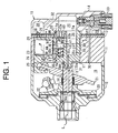
- FIGS. 1 through 3 A first preferred embodiment of the present invention will now be described with reference to FIGS. 1 through 3.
- the left side and the right side respectively correspond to the front side and the rear side of a compressor 10 in FIG. 1.
- the compressor 10 includes a cylinder block 11, a front housing 12 connected to the front end of the cylinder block 11, a rear housing 14 connected to the rear end of the cylinder block 11 through a valve port assembly 13.
- These cylinder block 11, front housing 12 and rear housing 14 cooperatively form a housing of the compressor 10.
- a crank chamber 15 is formed in a region surrounded by the cylinder block 11 and the front housing 12.
- a rotary shaft 16 extends through the crank chamber 15 and is rotatably supported by the front housing 12 and the cylinder block 11.
- the rotary shaft 16 is operatively coupled to an engine (not shown) for traveling a vehicle and is rotated by receiving power from the engine.
- a lug plate 20 is fixedly connected to the rotary shaft 16 in the crank chamber 15 so as to integrally rotate therewith.
- a swash plate or a cam plate 21 is accommodated in the crank chamber 15.
- the swash plate 21 is slidably and inclinably supported by the rotary shaft 16.
- a hinge mechanism 22 is interposed between the lug plate 20 and the swash plate 21. Accordingly, the swash plate 21 is integrally rotatable with the lug plate 20 and the rotary shaft 16 while being inclinable relative to the rotary shaft 16 with sliding movement in the direction of the rotation center axis (hereinafter, the axis) L of the rotary shaft 16 by hinge connection between the swash plate 21 and the lug plate 20 through the hinge mechanism 22 and also by support of the rotary shaft 16.
- the compressor 10 has a multi-cylinder piston type compression mechanism. As shown in FIGS. 1 and 2, a plurality of cylinder bores 23 (five in the first preferred embodiment, and only one of them being shown in FIG. 1) is formed In the cylinder block 11 to extend therethrough by surrounding the rear side of the rotary shaft 16 at equiangular positions. A single-headed piston 24 is accommodated in each cylinder bore 23 so as to reciprocate therein.
- the front and rear openings of the cylinder bore 23 is respectively closed by the piston 24 and the valve port assembly 13, and the cylinder bore 23 forms therein a compression chamber 26 which varies its volume in accordance with reciprocation of the piston 24.
- Each piston 24 engages with the outer periphery of the swash plate 21 through a pair of shoes 25. Accordingly, rotation of the swash plate 21 in accordance with rotation of the rotary shaft 16 is converted to reciprocation of the piston 24 through the shoes 25.
- the rear housing 14 forms therein a suction chamber 27, which is a part of suction pressure region, and a discharge chamber 28.
- the suction chamber 27 is formed at the center of the rear housing 14.
- the discharge chamber 28 is formed to surround the suction chamber 27.
- An external conduit connected to the low pressure side of a heat exchanger of an external refrigerant circuit (not shown) is connected to the suction chamber 27.
- Another external conduit connected to the high pressure side of the heat exchanger of the external refrigerant circuit is connected to the discharge chamber 28.
- This external refrigerant circuit and the compressor 10 cooperate to form a refrigerant circuit (a refrigeration cycle).
- the refrigerant gas in the suction chamber 27 is introduced into the compression chamber 26 through a suction valve device 55 provided in the cylinder block 11 by increasing volume of the compression chamber 26 as the piston 24 moves from the top dead center to the bottom dead center.
- the refrigerant gas introduced in the compression chamber 26 is compressed up to a predetermined pressure and discharged to the discharge chamber 28 through a discharge port 29 and a discharge valve 30 which are respectively formed in the valve port assembly 13 by reducing volume of the compression chamber 26 as the piston 24 moves from the bottom dead center to the top dead center.
- the compressor 10 provides a bleed passage 31, a supply passage 32 and a control valve 33 inside the housing thereof.
- the crank chamber 15 and the suction chamber 27 communicate with each other through the bleed passage 31.
- the bleed passage 31 has an axial passage 34 formed along the axis L of the rotary shaft 16.
- An inlet 34a of the axial passage 34 is opened to the crank chamber 15 near the lug plate 20, and an outlet 34b thereof is opened at the rear end surface of the rotary shaft 16.
- the discharge chamber 28 and the crank chamber 15 communicate with each other through the supply passage 32.
- a known electromagnetic control valve 33 is provided in the supply passage 32.
- the inclination angle of the swash plate 21 increases and the stroke of the piston 24 increases thereby to increase the displacement of the compressor 10.
- the inclination angle of the swash plate 21 reduces and stroke of the piston 24 reduces thereby to reduce the displacement of the compressor 10.
- the suction valve device 55 will now be described.
- the housing of the compressor 10 forms a cylindrical accommodating hole 17 in the center of the cylinder block 11 surrounded by the cylinder bores 23.
- the cylinder block 11 forms a boss 11 a at its rear end surface around the opening of the accommodating hole 17, and the boss 11a extends into the center portion of the rear housing 14 through the valve port assembly 13.
- the accommodating hole 17 and the suction chamber 27 are arranged in series in the direction of the axis L.
- the accommodating hole 17 and the compression chambers 26 are respectively in communication through a plurality of introducing passages 18 (five in the first preferred embodiment) formed radially in the cylinder block 11 around the axis L as a center.
- a rotary valve or a rotor 35 is rotatably accommodated in the accommodating hole 17.
- the rotary valve 35 substantially forms a cylinder with a bottom at the front side.
- An inner peripheral surface 17a of the accommodating hole 17 and an outer peripheral surface 35b of the rotary valve 35 slidably contact with each other.
- the front end side of the rotary valve 35 forms therein a communication hole 35c extending forward in the axial direction.
- An introducing chamber 36 which is a cylindrical space of the rotary valve 35 and the axial passage 34 of the rotary shaft 16 (the outlet 34b) are in communication through the communication hole 35c.
- the introducing passage 36 is in communication with the suction chamber 27.
- the communication hole 35c and the introducing chamber 36 are part of the bleed passage 31.
- the front end side of the rotary valve 35 is small in diameter (a small diameter portion 35a).
- the rotary shaft 16 forms a fitting hole 16a at its rear end surface facing the accommodating hole 17.
- the rotary valve 35 is press-fitted to the fitting hole 16a of the rotary shaft 16 with the small diameter portion 35a. Accordingly, the rotary shaft 16 and the rotary valve 35 are arranged along the same axis L and integrated with each other, so that the rotary valve 35 is rotated around the axis L of the rotary shaft 16 as a center with rotation of the rotary shaft 16, that is, with reciprocation of the piston 24.
- the outer peripheral surface 35b of the rotary valve 35 and the inner peripheral surface 17a of the accommodating hole 17 constitute a slide bearing surface for rotatably supporting the rear end portion of the rotary shaft 16.
- An outer wall 39 of the rotary valve 35 forms therein a suction guiding hole 37 in a predetermined angular range in the circumferential direction, and the suction guiding hole 37 constantly communicates with the introducing chamber 36.
- This suction guiding hole 37 serves as a suction guiding passage for sequentially communication between the introducing chamber 36, that is, the suction chamber 27, and the introducing passage 18 extending from the compression chamber 26 with rotation of the rotary valve 35.
- the suction guiding hole 37 of the rotary valve 35 communicates with the introducing passage 18 of the cylinder block 11. Accordingly, the refrigerant gas in the suction chamber 27 is introduced into the compression chamber 26 through the introducing chamber 36 and suction guiding hole 37 of the rotary valve 35 and the introducing passage 18 of the cylinder block 11 in this order. It is noted that the suction guiding hole 37 initiates communication with the introducing passage 18 (the compression chamber 26) during the volume-increasing process of the compression chamber 26.
- the suction guiding hole 37 is completely away from the introducing passage 18 in the circumferential direction thereby to stop introducing the refrigerant gas from the introducing chamber 36 to the compression chamber 26.
- a sealing region of the outer peripheral surface 35b of the rotary valve 35 keeps closed state between the introducing passage 18 and the introducing chamber 36, so that nothing prevents the refrigerant gas from being compressed and also the compressed refrigerant gas from being discharged to the discharge chamber 28.
- a first suction valve is constituted of the sealing region of the outer peripheral surface 35b for closing the introducing passage 18 and the suction guiding hole 37 for establishing communication between the introducing passage 18 and the introducing chamber 36.
- the suction guiding hole 37 is regarded as a first port of the first suction valve.
- a suction timing control mechanism (a suction timing control passage and a suction timing control valve) for constantly ensuring the appropriate timing of the suction initiation while the refrigerant gas is being introduced from the suction chamber 27 to the compression chamber 26 will now be described.
- a valve housing 41 is provided into the introducing chamber 36 of the rotary valve 35 by building up inwardly from a portion of the outer peripheral wall 39 of the rotary valve 35 in the circumferential direction.
- the valve housing 41 extends from the inner bottom end of the introducing chamber 36 to the opening end of the rotary valve 35.
- the valve housing 41 forms therein a cylindrical valve chamber 42 having opening at a rear end and extending along the direction of the axis L of the rotary valve 35.
- the rear end of the valve chamber 42 is opened to the suction chamber 27 at the opening end of the rotary valve 35.
- the inner space of the valve chamber 42 is closed by a tap body 43 which is fixedly inserted into the opening end of the valve chamber 42.
- the tap body 43 forms therein a valve hole 43a for communication between the suction chamber 27 and the inner space of the valve chamber 42.
- the opening of the valve hole 43a in the inner space side of the valve chamber 42 is located on an inner end surface 43b of the tap body 43.
- the inner space of the valve chamber 42 forms therein a step 42a in the inner peripheral surface near the middle with setting the side of the tap body 43 to be larger in diameter than the other side.
- a cylindrical poppet 44 is accommodated in the valve chamber 42.
- the poppet 44 is operable to slide between a closed position (as shown in FIG. 1) at which the valve hole 43a is closed such that a top end surface 44a of the poppet 44 contacts with the inner end surface 43b of the tap body 43 and an opened position (as shown in FIG. 3) at which the valve hole 43a is opened (fully opened) such that the outer periphery of a back surface 44b contacts with the wall surface of the step 42a.
- the top end surface 44a of the poppet 44 serves as a sealing surface
- the inner end surface 43b of the tap body 43 serves as a valve seat surface.
- the poppet 44 slides at a position offset from the rotary valve 35 and along the direction of the axis L of the rotary valve 35. That is, the poppet 44 is located offset from the axis L such that the central axis S of the valve chamber 42 is in parallel relation to the axis L of the rotary valve 35. More particularly, the poppet 44 is located such that the axis S is offset toward the side of the axis P of the piston 24 positioned at the top dead center relative to a hypothetical plane which intersects vertically another hypothetical plane including the axis L of the rotary valve 35 and the central axis P.
- a back pressure chamber 45 and a communication chamber 46 are respectively formed in the valve chamber 42 by arranging the poppet 44 in the valve chamber 42.
- the back pressure chamber 45 is located on the side of the back surface 44b of the poppet 44, that is, on the left side of FIG. 1.
- the communication chamber 46 is located on the side of the top end surface 44a of the poppet 44, that is, on the right side of FIG. 1.
- the rotary valve 35 forms a communication hole 47 extending therethrough in the radial direction at the rear end side of the outer peripheral wall 39. The inner end of the communication hole 47 is opened near the tap body 43 on the inner peripheral surface of the valve chamber 42.
- the outer end of the communication hole 47 is opened at the outer peripheral surface 35b of the rotary valve 35, and the opening portion of the communication hole 47 is provided on a sealing region which faces the introducing passage 18 connected to the compression chamber 26 which has almost completed the volume-reducing process. That is, the time when the communication hole 47 initiates communication with the introducing. passage 18 connected to the compression chamber 26 is during the volume-reducing process (almost completing the volume-reducing process in the first preferred embodiment). Accordingly, in a state where the above piston 24 is positioned at the top dead center, the communication hole 47 has already initiated communication with the introducing passage 18 connected to the corresponding compression chamber 26 of the above piston 24. Consequently, the communication hole 47 precedes the suction guiding hole 37 to communicate with the introducing passage 18 connected to the compression chamber 26 during the volume-increasing process.
- a suction timing control passage which is constituted of the valve hole 43a, the communication chamber 46 and the communication hole 47, constantly communicates with the suction chamber 27 at first end and precedes the suction guiding hole 37 to communicate with the introducing passage 18 connected to the compression chamber 26 during the volume-increasing process at second end.
- the valve hole 43a (strictly, the opening end on the side of the suction chamber 27) serves as the first end of the suction timing control passage
- the communication hole 47 (strictly, the outer end) serves as the second end of the suction timing control passage.
- a clearance (diameter difference) is provided between the outer peripheral surface of the poppet 44 and the inner peripheral surface of the valve chamber 42.
- the communication hole 47 and the back pressure chamber 45 are constantly in communication through the clearance between the poppet 44 and the valve chamber 42. Accordingly, in a state where the communication hole 47 is in communication with the introducing passage 18 connected to the compression chamber 26, pressure in the compression chamber 26 is applied to the back pressure chamber 45 through the communication hole 47 and the clearance between the poppet 44 and the valve chamber 42.
- An urging spring 48 constituted of a coil spring is interposed in the valve chamber 42 between the inner bottom surface of the valve chamber 42 and the back surface 44b of the poppet 44.
- a region on the front side relative to the step 42a in the valve chamber 42 (the small diameter portion) serves as a guide portion for guiding a fixed end of the urging spring 48 and stabilizing its position.
- the urging spring 48 urges the poppet 44 toward the tap body 43, that is, to close the valve hole 43a.
- the position of the poppet 44 that is, the opening and closing of the valve hole 43a by the poppet 44 is determined by balance between the sum of urging force of the urging spring 48 to close the valve and force to close the valve resulting from pressure in the back pressure chamber 45, that is, pressure in the compression chamber 26, applied to the back surface 44b and opposing force to open the valve resulting from pressure in the valve hole 43a (that is, pressure in the suction chamber 27) applied to the top end surface 44a.
- the urging spring 48 has a quite small urging force. Accordingly, when the pressure in the valve hole 43a is a little higher than the pressure in the back pressure chamber 45, the poppet 44 seated on the inner end surface 43b of the tap body 43 immediately leaves from the inner end surface 43b and moves to the position to contact with the step 42a. Also, when the pressure in the back pressure chamber 45 is a little higher than the pressure in the communication chamber 46 in a state where the valve hole 43a is opened, the poppet 44 immediately leaves from the step 42a and sits on the inner end surface 43b of the tap body 43 thereby to close the valve hole 43a.
- valve housing 41, the valve chamber 42, the valve hole 43a, the poppet 44, the back pressure chamber 45, the communication chamber 46, the communication hole 47, the urging spring 48 and the like cooperatively form a suction timing control valve (a second suction valve) constituted of a differential pressure regulating valve.
- a suction timing control valve a second suction valve
- the poppet 44 may be regarded as a valve body of the suction timing control valve
- the communication hole 47 may be regarded as a second port formed in the second suction valve.
- the communication hole 47 of the rotary valve 35 precedes the suction guiding hole 37 to communicate with the introducing passage 18 connected to the compression chamber 26.
- the poppet 44 keeps the valve hole 43a closed (as shown in FIC. 1) by force resulting from the pressure in the back pressure chamber 45 and the urging force of the urging spring 48. Accordingly, the timing of the suction initiation is delayed, so that the pressure in the compression chamber 26 is decreased due to an increase of the volume of the compression chamber 26.
- the refrigerant gas is prevented from flowing from the compression chamber 26 back to the suction chamber 27 when the compression chamber 26 initiates communication with the suction chamber 27.
- the position and region of the opening of the communication hole 47 and the position and region of the opening of the suction guiding hole 37 are determined on the outer peripheral surface 35b of the rotary valve 35 such that the suction of the refrigerant gas from the suction chamber 27 to the compression chamber 26 is initiated by opening the valve hole 43a by the poppet 44.
- the suction of the refrigerant gas from the suction chamber 27 to the compression chamber 26 is designed to continue during a process when the communication with the introducing passage 18 is shifted from the communication hole 47 to the suction guiding hole 37. That is, a circumferential width 35d on the outer peripheral surface 35b between the opening of the communication hole 47 on the outer peripheral surface 35b of the rotary valve 35 and the opening of the suction guiding hole 37 is narrower than the maximum width in the circumferential direction of the opening (the opening on the inner peripheral surface 17a of the accommodating hole 17) of the introducing passage 18 such that the two openings are simultaneously communicate with the same introducing passage 18 (in other words, the same compression chamber 26).
- the second valve portion 50a-2 decreases the opening degree of the suction guiding hole 37 to the introducing chamber 36. That is, for example, in a state where the first valve portion 50a-1 closes the communication hole 47 at the time when the suction guiding hole 37 initiates communication with the compression chamber 26 (the appropriate timing of the suction initiation has not appeared), the second valve portion 50a-2 decreases the opening degree of the suction guiding hole 37 to the introducing chamber 36. Accordingly, the amount of refrigerant gas flowing from the compression chamber 26 back to the side of the suction guiding hole 37 is reduced thereby to further efficiently prevent generation of suction pulsation and a decrease in volumetric efficiency.
- the provision of the second valve portion 50a-2 in the poppet 50 enables the compressor 10 to appropriately deal with "large delay of the appropriate timing of the suction initiation" which is not dealt with only by the first valve portion 50a-1.
- the communication hole 47 which precedes the suction guiding hole 37, faces another compression chamber 26 which is different from the compression chamber 26 with which the suction guiding hole 37 is in communication, as shown in FIG. 6. Then, when the appropriate timing of the suction initiation delays largely during the small displacement of the compressor 10, the first valve portion 50a-1 does not open the communication hole 47 facing the above compression chamber 26, while the communication hole 47 is shifted to face another compression chamber 26.
- the communication hole 47 is constantly closed by the first valve portion 50a-1 thereby to constantly reduce the opening degree of the suction guiding hole 37 by the second valve portion 50a-2.
- the refrigerant gas flowing toward the compression chamber 26 through the suction guiding hole 37 is throttled and rectified thereby to efficiently prevent suction pulsation around all stages of volume-increasing process during the small displacement of the compressor 10.
- the poppet valve is employed as the suction timing control valve.
- a reed valve is employed as the suction timing control valve.
- the suction timing control valve constituted of a reed valve is structurally simple, for example, in comparison to the poppet valve thereby to reduce the number of manufacturing processes for the suction timing control valve.
- the outer peripheral surface 35b of the rotary valve 35 forms therein a valve accommodating recess 65, and the inner space of the valve accommodating recess 65 and the introducing chamber 36 are in communication through a communication hole 66.
- the valve accommodating recess 65 serves as the same as the communication hole 47 (as shown in FIG. 2) of the above preferred embodiments. Accordingly, an opening 65a of the valve accommodating recess 65 precedes the suction guiding hole 37 communicating with the introducing passage 18 connected to the compression chamber 26 during the volume-increasing process (as shown in FIG. 2).
- the valve accommodating recess 65, the communication hole 66 and the introducing chamber 36 cooperatively form the suction timing control passage.
- the introducing chamber 36 serves as a first end of the suction timing control passage
- the valve accommodating recess 65 serves as a second end of the suction timing control passage.
- a reed-type valve body 67 is accommodated in the valve accommodating recess 65, and the valve body 67 opens and closes the communication hole 66 in response to pressure difference between the introducing chamber 36 and the valve accommodating recess 65.
- the maximum opening degree of the valve body 67 is regulated by a retainer 68 which is arranged in the valve accommodating recess 65. It is noted that the valve body 67 has an extremely small urging force. Accordingly, when the introducing chamber 36 is a little higher in pressure than the valve accommodating recess 65, the valve body 67 immediately moves to contact with the retainer 66 and opens the communication hole 66. Also, in this opening state of the communication hole 66, when the valve accommodating recess 65 is a little higher in pressure than the introducing chamber 36, the valve body 67 immediately closes the communication hole 66.
- the valve accommodating recess 65, the communication hole 66, the valve body 67, the retainer 68 and the like cooperatively form the suction timing control valve (the second suction valve) constituted of pressure difference regulating valve.
- the valve accommodating recess 65 is regarded as a second port of the second suction valve. According to the fourth preferred embodiment, the same advantageous effects to those mentioned in the paragraphs (1) through (5) of the first preferred embodiment are obtained.
- the communication hole 47 initiates communication with the compression chamber 26 during the volume-reducing process of the compression chamber 26.
- the communication hole 47 initiates communication with the compression chamber 26 at the time when the compression chamber 26 completes a volume-reducing process (when the piston 24 is positioned at the top dead center). In this case, the same advantageous effect as mentioned in the paragraph (4) of the first preferred embodiment is obtained.
- the communication hole 47 initiates communication with the compression chamber 26 during the volume-reducing process of the compression chamber 26. In an alternative embodiment, the communication hole 47 initiates communication with the compression chamber 26 at the time before the suction guiding hole 37 initiates communication with the compression chamber 26 during the volume-increasing process of the compression chamber 26.
- the circumferential width 35d between the opening of the communication hole 47 and the opening of the suction guiding hole 37 on the outer peripheral surface 35b of the rotary valve 35 is narrower than the maximum width in the circumferential direction at the opening of the introducing passage 18 (the opening at the inner peripheral surface 17a of the accommodating hole 17) such that both the openings simultaneously communicate with the same introducing passage 18.
- a circumferential width between the opening of the communication hole 47 and the opening of the suction guiding hole 37 is wider than the maximum width of the opening of the introducing passage 18 such that both the openings do not simultaneously communicate with the same introducing passage 18.
- a passage for communication between the suction guiding hole 37 and communication hole 47 and the compression chamber. 26 is the single introducing passage 18 which is shared by the holes 37, 47.
- a passage for communication between the communication hole 47 and the compression chamber 26 is provided in the cylinder block independently from the introducing passage 18.
- the opening of the communication hole 47 on the outer peripheral surface 35b of the rotary valve 35 is arranged offset from the opening of the suction guiding hole 37 in the direction of the axis L.
- an urging spring for urging the poppet 50 toward the side of the suction chamber 27 is arranged in the back pressure chamber 45, that is, between the inner bottom surface of the introducing chamber 36 and the inner bottom surface of the poppet 50.
- the outer peripheral wall 39 of the rotary valve 35 doubles as the cylindrical wall for slidably holding the poppet 50.
- an exclusive cylindrical wall for the poppet 50 is provided coaxially with the outer peripheral wall 39. That is, the rotary valve 35 has a double cylindrical structure including the outer peripheral wall 39 on the outer side and the cylindrical wall arranged inside the outer peripheral wall 39 for holding the poppet.
- the poppet 50 adjusts the opening degree of the suction guiding hole 37.
- the poppet 50 is not related to adjusting the opening degree of the suction guiding hole 37.
- the suction guiding hole 37 and the communication hole 47 are arranged such that they are overlapped in the direction of the axis S, however, in an alternative embodiment, the communication hole 47 is arranged on the front side relative to the suction guiding hole 37, while the circular clip 51 is arranged on the front side relative to the suction guiding hole 37.
- a portion for opening and closing the communication hole 66 in the valve body 67 serves as the first valve portion, while the second valve portion is provided in the valve body 67 for adjusting the opening degree of the suction guiding hole 37.
- the present invention is applied to a wobble type variable displacement compressor.
- the present invention is applied to a double-headed piston type compressor.
- the present invention is applied to a wave cam piston type compressor.
- a piston is respectively accommodated in a plurality of cylinder bores arranged around a rotary shaft.
- a rotary valve has a suction guiding passage for introducing gas from a suction pressure region into a compression chamber when in communication therebetween.
- a suction timing control passage is formed in the rotary valve and is constantly in communication at its first end with the suction pressure region, while preceding the suction guiding passage communicating at its second end with the compression chamber.
- a suction timing control valve is arranged in the control passage, having a valve body which opens and closes the control passage in response to difference between force resulting from pressure on a side of the suction pressure region to open the valve body and force resulting from pressure on a side of the compression chamber to close the valve body.
Landscapes
- Engineering & Computer Science (AREA)
- General Engineering & Computer Science (AREA)
- Mechanical Engineering (AREA)
- Physics & Mathematics (AREA)
- Thermal Sciences (AREA)
- Manufacturing & Machinery (AREA)
- Compressors, Vaccum Pumps And Other Relevant Systems (AREA)
- Compressor (AREA)
- Applications Or Details Of Rotary Compressors (AREA)
Applications Claiming Priority (2)
| Application Number | Priority Date | Filing Date | Title |
|---|---|---|---|
| JP2003191364A JP2004332709A (ja) | 2003-03-07 | 2003-07-03 | ピストン式圧縮機 |
| JP2003191364 | 2003-07-03 |
Publications (2)
| Publication Number | Publication Date |
|---|---|
| EP1493923A2 true EP1493923A2 (fr) | 2005-01-05 |
| EP1493923A3 EP1493923A3 (fr) | 2006-11-15 |
Family
ID=33432349
Family Applications (1)
| Application Number | Title | Priority Date | Filing Date |
|---|---|---|---|
| EP04015486A Withdrawn EP1493923A3 (fr) | 2003-07-03 | 2004-07-01 | Compresseur à plateau en biais |
Country Status (5)
| Country | Link |
|---|---|
| US (1) | US20050031459A1 (fr) |
| EP (1) | EP1493923A3 (fr) |
| KR (1) | KR20050004099A (fr) |
| CN (1) | CN1576581A (fr) |
| BR (1) | BRPI0402635A (fr) |
Cited By (1)
| Publication number | Priority date | Publication date | Assignee | Title |
|---|---|---|---|---|
| EP1688618A1 (fr) * | 2005-01-27 | 2006-08-09 | Kabushiki Kaisha Toyota Jidoshokki | Compresseur à plateau en biais |
Families Citing this family (5)
| Publication number | Priority date | Publication date | Assignee | Title |
|---|---|---|---|---|
| DE102005007849A1 (de) * | 2005-01-25 | 2006-08-17 | Valeco Compressor Europe Gmbh | Axialkolbenverdichter |
| US8157538B2 (en) | 2007-07-23 | 2012-04-17 | Emerson Climate Technologies, Inc. | Capacity modulation system for compressor and method |
| BRPI1007407A2 (pt) | 2009-01-27 | 2016-02-16 | Emerson Climate Technologies | sistema e método de descarregamento para um compressor |
| US20150285230A1 (en) * | 2014-04-07 | 2015-10-08 | Halla Visteon Climate Control Corp. | Seal structure for a rotary valve compressor |
| CN114508480A (zh) * | 2022-03-11 | 2022-05-17 | 骑记(深圳)科技有限公司 | 双压气泵 |
Family Cites Families (4)
| Publication number | Priority date | Publication date | Assignee | Title |
|---|---|---|---|---|
| JP2707896B2 (ja) * | 1991-12-17 | 1998-02-04 | 株式会社豊田自動織機製作所 | ピストン型圧縮機における冷媒ガス吸入案内機構 |
| US5478212A (en) * | 1992-03-04 | 1995-12-26 | Nippondenso Co., Ltd. | Swash plate type compressor |
| US5529461A (en) * | 1993-12-27 | 1996-06-25 | Kabushiki Kaisha Toyoda Jidoshokki Seisakusho | Piston type variable displacement compressor |
| JP3482686B2 (ja) * | 1994-06-07 | 2003-12-22 | 株式会社豊田自動織機 | 往復動型圧縮機 |
-
2004
- 2004-07-01 EP EP04015486A patent/EP1493923A3/fr not_active Withdrawn
- 2004-07-02 CN CNA2004100766464A patent/CN1576581A/zh active Pending
- 2004-07-02 KR KR1020040051472A patent/KR20050004099A/ko not_active Ceased
- 2004-07-02 BR BR0402635-7A patent/BRPI0402635A/pt not_active IP Right Cessation
- 2004-07-02 US US10/884,593 patent/US20050031459A1/en not_active Abandoned
Cited By (2)
| Publication number | Priority date | Publication date | Assignee | Title |
|---|---|---|---|---|
| EP1688618A1 (fr) * | 2005-01-27 | 2006-08-09 | Kabushiki Kaisha Toyota Jidoshokki | Compresseur à plateau en biais |
| US7699585B2 (en) | 2005-01-27 | 2010-04-20 | Kabushiki Kaisha Toyota Jidoshokki | Swash plate type compressor |
Also Published As
| Publication number | Publication date |
|---|---|
| CN1576581A (zh) | 2005-02-09 |
| US20050031459A1 (en) | 2005-02-10 |
| KR20050004099A (ko) | 2005-01-12 |
| BRPI0402635A (pt) | 2005-05-24 |
| EP1493923A3 (fr) | 2006-11-15 |
Similar Documents
| Publication | Publication Date | Title |
|---|---|---|
| US7918656B2 (en) | Suction throttle valve of a compressor | |
| EP1921313B1 (fr) | Robinet d'étranglement d'aspiration de compresseur | |
| US7204098B2 (en) | Oil separation structure for refrigerant compressor | |
| KR101607711B1 (ko) | 가변용량형 사판식 압축기 | |
| US9228577B2 (en) | Swash plate type variable displacement compressor | |
| EP0940581A2 (fr) | Amortisseur des pulsations de pression pour le réfoulement d'un compresseur | |
| JPH08326655A (ja) | 斜板式コンプレッサ | |
| EP1959137B1 (fr) | Robinet d'étranglement d'aspiration de compresseur de type à déplacement variable | |
| US20090220356A1 (en) | Swash plate type variable displacement compressor | |
| EP1493923A2 (fr) | Compresseur à plateau en biais | |
| EP1486669A2 (fr) | Compresseur à pistons | |
| KR102547594B1 (ko) | 가변 용량 사판식 압축기 | |
| KR20120040582A (ko) | 가변용량형 사판식 압축기 | |
| JP7511702B2 (ja) | 斜板式コンプレッサー | |
| KR20150060199A (ko) | 왕복식 압축기 | |
| JP2004332709A (ja) | ピストン式圧縮機 | |
| JPH08312528A (ja) | 斜板式可変容量型コンプレッサ | |
| EP1384888A2 (fr) | Compresseur à piston | |
| KR102717001B1 (ko) | 사판식 압축기 | |
| US20060222513A1 (en) | Swash plate type variable displacement compressor | |
| EP1096145A2 (fr) | Clapet d'aspiration pour compresseur volumétrique à dèbit variable | |
| JP3873861B2 (ja) | 斜板型可変容量圧縮機 | |
| KR101599549B1 (ko) | 가변용량형 사판식 압축기 | |
| JP2503566B2 (ja) | 可変容量型斜板式圧縮機 | |
| KR20190124673A (ko) | 왕복식 압축기 |
Legal Events
| Date | Code | Title | Description |
|---|---|---|---|
| PUAI | Public reference made under article 153(3) epc to a published international application that has entered the european phase |
Free format text: ORIGINAL CODE: 0009012 |
|
| 17P | Request for examination filed |
Effective date: 20040701 |
|
| AK | Designated contracting states |
Kind code of ref document: A2 Designated state(s): AT BE BG CH CY CZ DE DK EE ES FI FR GB GR HU IE IT LI LU MC NL PL PT RO SE SI SK TR |
|
| AX | Request for extension of the european patent |
Extension state: AL HR LT LV MK |
|
| PUAL | Search report despatched |
Free format text: ORIGINAL CODE: 0009013 |
|
| AK | Designated contracting states |
Kind code of ref document: A3 Designated state(s): AT BE BG CH CY CZ DE DK EE ES FI FR GB GR HU IE IT LI LU MC NL PL PT RO SE SI SK TR |
|
| AX | Request for extension of the european patent |
Extension state: AL HR LT LV MK |
|
| GRAP | Despatch of communication of intention to grant a patent |
Free format text: ORIGINAL CODE: EPIDOSNIGR1 |
|
| STAA | Information on the status of an ep patent application or granted ep patent |
Free format text: STATUS: THE APPLICATION IS DEEMED TO BE WITHDRAWN |
|
| AKX | Designation fees paid |
Designated state(s): DE FR IT |
|
| 18D | Application deemed to be withdrawn |
Effective date: 20070201 |