EP1493926A2 - Procédé de fabrication d'une pompe à engrenage interne - Google Patents
Procédé de fabrication d'une pompe à engrenage interne Download PDFInfo
- Publication number
- EP1493926A2 EP1493926A2 EP04014672A EP04014672A EP1493926A2 EP 1493926 A2 EP1493926 A2 EP 1493926A2 EP 04014672 A EP04014672 A EP 04014672A EP 04014672 A EP04014672 A EP 04014672A EP 1493926 A2 EP1493926 A2 EP 1493926A2
- Authority
- EP
- European Patent Office
- Prior art keywords
- outer ring
- teeth
- rotor gear
- contour
- radius
- Prior art date
- Legal status (The legal status is an assumption and is not a legal conclusion. Google has not performed a legal analysis and makes no representation as to the accuracy of the status listed.)
- Granted
Links
Images

Classifications
-
- F—MECHANICAL ENGINEERING; LIGHTING; HEATING; WEAPONS; BLASTING
- F04—POSITIVE - DISPLACEMENT MACHINES FOR LIQUIDS; PUMPS FOR LIQUIDS OR ELASTIC FLUIDS
- F04C—ROTARY-PISTON, OR OSCILLATING-PISTON, POSITIVE-DISPLACEMENT MACHINES FOR LIQUIDS; ROTARY-PISTON, OR OSCILLATING-PISTON, POSITIVE-DISPLACEMENT PUMPS
- F04C2/00—Rotary-piston machines or pumps
- F04C2/08—Rotary-piston machines or pumps of intermeshing-engagement type, i.e. with engagement of co-operating members similar to that of toothed gearing
- F04C2/10—Rotary-piston machines or pumps of intermeshing-engagement type, i.e. with engagement of co-operating members similar to that of toothed gearing of internal-axis type with the outer member having more teeth or tooth-equivalents, e.g. rollers, than the inner member
-
- B—PERFORMING OPERATIONS; TRANSPORTING
- B23—MACHINE TOOLS; METAL-WORKING NOT OTHERWISE PROVIDED FOR
- B23F—MAKING GEARS OR TOOTHED RACKS
- B23F15/00—Methods or machines for making gear wheels of special kinds not covered by groups B23F7/00 - B23F13/00
-
- B—PERFORMING OPERATIONS; TRANSPORTING
- B62—LAND VEHICLES FOR TRAVELLING OTHERWISE THAN ON RAILS
- B62D—MOTOR VEHICLES; TRAILERS
- B62D5/00—Power-assisted or power-driven steering
- B62D5/06—Power-assisted or power-driven steering fluid, i.e. using a pressurised fluid for most or all the force required for steering a vehicle
- B62D5/09—Power-assisted or power-driven steering fluid, i.e. using a pressurised fluid for most or all the force required for steering a vehicle characterised by means for actuating valves
- B62D5/093—Telemotor driven by steering wheel movement
- B62D5/097—Telemotor driven by steering wheel movement gerotor type
-
- B—PERFORMING OPERATIONS; TRANSPORTING
- B62—LAND VEHICLES FOR TRAVELLING OTHERWISE THAN ON RAILS
- B62D—MOTOR VEHICLES; TRAILERS
- B62D5/00—Power-assisted or power-driven steering
- B62D5/06—Power-assisted or power-driven steering fluid, i.e. using a pressurised fluid for most or all the force required for steering a vehicle
- B62D5/30—Safety devices, e.g. alternate emergency power supply or transmission means to ensure steering upon failure of the primary steering means
- B62D5/32—Safety devices, e.g. alternate emergency power supply or transmission means to ensure steering upon failure of the primary steering means for telemotor systems
-
- F—MECHANICAL ENGINEERING; LIGHTING; HEATING; WEAPONS; BLASTING
- F04—POSITIVE - DISPLACEMENT MACHINES FOR LIQUIDS; PUMPS FOR LIQUIDS OR ELASTIC FLUIDS
- F04C—ROTARY-PISTON, OR OSCILLATING-PISTON, POSITIVE-DISPLACEMENT MACHINES FOR LIQUIDS; ROTARY-PISTON, OR OSCILLATING-PISTON, POSITIVE-DISPLACEMENT PUMPS
- F04C2/00—Rotary-piston machines or pumps
- F04C2/08—Rotary-piston machines or pumps of intermeshing-engagement type, i.e. with engagement of co-operating members similar to that of toothed gearing
- F04C2/082—Details specially related to intermeshing engagement type machines or pumps
- F04C2/084—Toothed wheels
-
- F—MECHANICAL ENGINEERING; LIGHTING; HEATING; WEAPONS; BLASTING
- F04—POSITIVE - DISPLACEMENT MACHINES FOR LIQUIDS; PUMPS FOR LIQUIDS OR ELASTIC FLUIDS
- F04C—ROTARY-PISTON, OR OSCILLATING-PISTON, POSITIVE-DISPLACEMENT MACHINES FOR LIQUIDS; ROTARY-PISTON, OR OSCILLATING-PISTON, POSITIVE-DISPLACEMENT PUMPS
- F04C2/00—Rotary-piston machines or pumps
- F04C2/08—Rotary-piston machines or pumps of intermeshing-engagement type, i.e. with engagement of co-operating members similar to that of toothed gearing
- F04C2/10—Rotary-piston machines or pumps of intermeshing-engagement type, i.e. with engagement of co-operating members similar to that of toothed gearing of internal-axis type with the outer member having more teeth or tooth-equivalents, e.g. rollers, than the inner member
- F04C2/103—Rotary-piston machines or pumps of intermeshing-engagement type, i.e. with engagement of co-operating members similar to that of toothed gearing of internal-axis type with the outer member having more teeth or tooth-equivalents, e.g. rollers, than the inner member one member having simultaneously a rotational movement about its own axis and an orbital movement
- F04C2/104—Rotary-piston machines or pumps of intermeshing-engagement type, i.e. with engagement of co-operating members similar to that of toothed gearing of internal-axis type with the outer member having more teeth or tooth-equivalents, e.g. rollers, than the inner member one member having simultaneously a rotational movement about its own axis and an orbital movement having an articulated driving shaft
-
- F—MECHANICAL ENGINEERING; LIGHTING; HEATING; WEAPONS; BLASTING
- F04—POSITIVE - DISPLACEMENT MACHINES FOR LIQUIDS; PUMPS FOR LIQUIDS OR ELASTIC FLUIDS
- F04C—ROTARY-PISTON, OR OSCILLATING-PISTON, POSITIVE-DISPLACEMENT MACHINES FOR LIQUIDS; ROTARY-PISTON, OR OSCILLATING-PISTON, POSITIVE-DISPLACEMENT PUMPS
- F04C2230/00—Manufacture
- F04C2230/10—Manufacture by removing material
Definitions
- the invention relates to a method for producing a displacer unit according to the preamble of claim 1.
- Such displacement units are used in hydraulic steering devices for metering a steering oil flow and in hydraulic motors for generating a drive torque for a variety of applications.
- Displacement units operating on the gerotor principle are well known.
- she consist of a fixed outer ring with an internal toothing and an im Inside the outer ring arranged and meshing with the outer ring rotor gear with an external toothing. It has the internal teeth of the outer ring one tooth more than the external teeth of the rotor gear, so that the rotor gear a rotation about its own axis and a pendulum motion around the Axle of the outer ring can perform, with both movements are superimposed.
- Due to the different numbers of teeth of the fixed outer ring and the circumferential Runner gear form variable-volume chambers, which are with the movement of the rotor gear zoom in or out and so alternately to suction or pressure chambers.
- the displacer unit is flanged on the end face to a housing in which a rotary valve control unit is located.
- the rotary valve control unit consists of a control sleeve fitted with a clearance in the housing and a control piston running in the control sleeve, both of which are rotatable relative to one another relative to the force of a spring and limited to one another.
- the internal control piston is non-rotatable with a hand wheel and the outer control sleeve is rotatably connected via a drive shaft to the rotor gear of the displacer unit.
- the control sleeve has in cooperation with the housing radial and axial channels, which establish a hydraulic connection on the one hand between an inlet port located in the housing and the suction chambers of the displacer unit and on the other hand between the pressure chambers of the displacer unit and also located in the housing outlet port.
- the inlet port is connected to a supply pump and the outlet port to a steering cylinder.
- In a neutral position all channels of the rotary valve control valve are closed and the applied supply current is returned unused to the tank.
- Upon deflection of the rotary valve control valve open the channels and provided by the supply pump oil flow is divided depending on the size of the deflection in a metered by the displacer unit steering oil flow and a short-circuit current.
- the supply pump driven by the handwheel displacement unit of the steering device acts as a pump and supplies the steering cylinder with a sufficient flow of oil.
- this displacer unit in a hydraulic motor becomes, for example shown in WO 96/05437.
- the displacer unit is the front side of a Flanged housing.
- an output shaft is supported with play, on the one hand protrudes from the housing and the other mechanically via a propeller shaft is connected to the rotor gear of the displacer unit.
- the output shaft forms together with the housing radial and axial control channels, which has an inlet connection and a drain port with the variable volume chambers of Connect displacer unit.
- the pressure oil flow provided by a supply pump is via the control channels passed in the housing to the displacer unit, where he turns the rotor gear in rotation added. This rotational movement is transmitted mechanically to the output shaft.
- These displacement units are manufactured by first determining the number of teeth, the pitch circles of the teeth and the radius of the teeth. After these parameters, the outer ring is first made with its relatively simple inner contour, the inner contour is cleared and then finely ground. Then, on the basis of the same parameters and with the aid of a complicated coordinate midpoint equation, the outer contour matching the inner contour of the outer ring is calculated for the rotor gear wheel and manufactured in a complex working method. In this case there is a desire to tune the outer contour of the revolving rotor gear wheel on the inner contour of the fixed outer ring, on the one hand to increase the inner tightness smallest possible play between the two contours and on the other hand a smooth movement of the rotor gear is guaranteed.
- the invention is therefore based on the object, the function-related play between the inner contour of the outer ring and the outer contour of the rotor gear of a generic displacement unit to reduce without restriction of freedom from running and to propose a simple manufacturing process.
- This object is solved by the characterizing features of claim 1.
- the new method eliminates the aforementioned disadvantages of the prior art.
- the sealing behavior between adjacent and different pressures having volume variable chambers is sealed against each other stronger. This is due to the fact that the sealing gap between the two contours of outer ring and rotor gear is greatly reduced. This leads to lower leakage.
- a further reduction in leakage is achieved by the fact that the inner contour of the outer ring and the outer contour of the rotor gear are further approximated in its course by increasing the radius of the teeth of the outer ring and thus form a larger sealing surface.
- This enlarged sealing surface shows over the previous sealing edge an improved sealing behavior.
- the particular advantage of the new method lies in the fact that these advantages are achieved with a simplified method.
- the hydraulic steering device consists in the main of a Housing 1 with a rotary valve control valve and working on the gerotor principle Displacer unit 2, the front side with the help of a cover 3 and seven screws 4 is flanged to the housing 1.
- the rotary valve control valve consists of an outer, in the housing 1 with game fitted control sleeve 5 and a inner, running in the control sleeve 5 control piston 6.
- the internal control piston 6 of the rotary valve control valve on the one hand has a rotationally fixed connection with a not shown handwheel.
- Within the control piston 6 is located a propeller shaft 7, on the one hand via a, the control piston 6 penetrating pin 8 with the outer control sleeve 5 is connected.
- This pen 8 limited in interaction with a enlarged bore in the inner control piston 6 the angle of rotation between the Control sleeve 5 and the control piston 6.
- the control sleeve 5 and the control piston 6 support mutually within the limited angle of rotation by a radially arranged Spring element 9 from.
- the cardan shaft 7, on the other hand, has a spherical toothed hub profile 10 for a mechanical connection with the displacer unit 2.
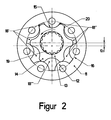
- This displacer unit 2 consists, as also shown in FIG. 2, of an outer ring eleventh with inner teeth 12 and an inner rotor gear 13 with outer teeth 14.
- each tooth 12 of the outer ring 11 as part of a cylinder with a Radius 15 formed and each tooth 12 lies with its center on a common Circuit 16.
- the outer ring 11 is equipped with a tooth 12 more than the rotor gear 13 has teeth 14.
- the Outer ring 11 seven teeth 12 and the rotor gear 13 six teeth 14 on.
- the rotary valve control valve in the housing 1 is now connected both mechanically and hydraulically with the displacer unit 2.
- the rotor gearwheel 13 has an inner gear hub profile 19, in which the gear hub profile 10 of the cardan shaft 7 engages from the rotary valve control valve.
- the housing 1 and the control sleeve 5 and the control piston 6 of the rotary valve control valve are equipped with radial and axial channels which connect the volume variable chambers 18 of the displacer unit 2 with a hydraulic supply device on the one hand and with a hydraulic load on the other.
- variable-volume chambers 18 of the displacer unit 2 are subdivided into three juxtaposed and increasing suction chambers 18 'and three likewise juxtaposed and decreasing pressure chambers 18'.
- "Between the three suction chambers 18 'and the three pressure chambers 18" is a pressure-neutral chamber 18 "'.
- Each of the variable volume chambers 18 ', 18 “, 18'” is separated from the adjacent variable volume chamber 18 ', 18 ", 18'” by a sealing surface 20, consisting of the rolling contours of the fixed outer ring 11 and the circumferential Runner gear 13 results and which is always of great importance, if the adjacent variable volume chambers 18 ', 18 ", 18'” have different pressures.
- the displacer unit 2 is manufactured as follows. First, a desired contour for the inner contour of the outer ring 11 is determined, in which the number of teeth 12, the radius 15 of all teeth 12 and the diameter of the common pitch circle 16 of all teeth 12 are specified. According to this information, the outer contour of the rotor gear 13 is calculated using a known coordinate center equation of the nominal contour of the outer ring 11 and then produced in a conventional manner, the last operation is the fine grinding.
- a radius 15 of all teeth 12 is used, which deviates from the radius for the calculation of the outer contour of the rotor gear 13 and which is selected to be larger by a predetermined amount. This increased degree is within the calculated game between the desired contour of the outer ring 11 and the outer contour of the rotor gear 13 produced and allows just a problem-free assembly of outer ring and rotor gear.
- the radius 15 is increased to the backlash between the two contours.
- the production contour of the rotor gear 13 underlying target contour of the outer ring 11 is distorted.
- This distorted inner contour of the outer ring 11 is then made again in a conventional manner, the last operation is again a fine grinding.
- the rotor gear 13 is mounted in the outer ring 11 and both parts are run, for example, by lapping to smooth running each other and thus both contours aligned.
Landscapes
- Engineering & Computer Science (AREA)
- Mechanical Engineering (AREA)
- General Engineering & Computer Science (AREA)
- Chemical & Material Sciences (AREA)
- Combustion & Propulsion (AREA)
- Transportation (AREA)
- Rotary Pumps (AREA)
- Details And Applications Of Rotary Liquid Pumps (AREA)
- Gears, Cams (AREA)
Priority Applications (1)
| Application Number | Priority Date | Filing Date | Title |
|---|---|---|---|
| PL04014672T PL1493926T3 (pl) | 2003-06-30 | 2004-06-23 | Sposób wytwarzania pompy z kołem zębatym o uzębieniu wewnętrznym |
Applications Claiming Priority (2)
| Application Number | Priority Date | Filing Date | Title |
|---|---|---|---|
| DE10329271A DE10329271B3 (de) | 2003-06-30 | 2003-06-30 | Verfahren zur Herstellung einer nach dem Gerotorprinzip arbeitenden Verdrängereinheit für hydraulische Lenkeinrichtungen und für Hydraulikmotore |
| DE10329271 | 2003-06-30 |
Publications (3)
| Publication Number | Publication Date |
|---|---|
| EP1493926A2 true EP1493926A2 (fr) | 2005-01-05 |
| EP1493926A3 EP1493926A3 (fr) | 2005-08-31 |
| EP1493926B1 EP1493926B1 (fr) | 2006-11-22 |
Family
ID=32309089
Family Applications (1)
| Application Number | Title | Priority Date | Filing Date |
|---|---|---|---|
| EP04014672A Expired - Lifetime EP1493926B1 (fr) | 2003-06-30 | 2004-06-23 | Procédé de fabrication d'une pompe à engrenage interne |
Country Status (5)
| Country | Link |
|---|---|
| EP (1) | EP1493926B1 (fr) |
| AT (1) | ATE346239T1 (fr) |
| DE (2) | DE10329271B3 (fr) |
| DK (1) | DK1493926T3 (fr) |
| PL (1) | PL1493926T3 (fr) |
Cited By (4)
| Publication number | Priority date | Publication date | Assignee | Title |
|---|---|---|---|---|
| CN102536809A (zh) * | 2011-12-12 | 2012-07-04 | 马燕翔 | 无定子磨损的叶片泵及液压马达和耙吸式泥浆泵 |
| US11549507B2 (en) | 2021-06-11 | 2023-01-10 | Genesis Advanced Technology Inc. | Hypotrochoid positive-displacement machine |
| US11965509B2 (en) | 2022-02-28 | 2024-04-23 | Genesis Advanced Technology Inc. | Energy transfer machine for corrosive fluids |
| US12168980B2 (en) | 2023-04-20 | 2024-12-17 | Genesis Advanced Technology Inc. | Hypotrochoid positive-displacement machine |
Family Cites Families (4)
| Publication number | Priority date | Publication date | Assignee | Title |
|---|---|---|---|---|
| DD99758A1 (fr) * | 1971-07-22 | 1973-08-20 | ||
| JPS61210283A (ja) * | 1985-03-13 | 1986-09-18 | Yamada Seisakusho:Kk | トロコイド噛み合いする内接歯車ポンプのアウタ−ロ−タ−曲線修正方法 |
| DE4428270C1 (de) * | 1994-08-10 | 1996-03-21 | Hydraulik Nord Gmbh | Gerotormotor mit Deckelzuführung |
| JP3326061B2 (ja) * | 1995-11-30 | 2002-09-17 | 三菱自動車工業株式会社 | 内接歯車式ポンプ |
-
2003
- 2003-06-30 DE DE10329271A patent/DE10329271B3/de not_active Expired - Fee Related
-
2004
- 2004-06-23 EP EP04014672A patent/EP1493926B1/fr not_active Expired - Lifetime
- 2004-06-23 DE DE502004002053T patent/DE502004002053D1/de not_active Expired - Lifetime
- 2004-06-23 AT AT04014672T patent/ATE346239T1/de not_active IP Right Cessation
- 2004-06-23 PL PL04014672T patent/PL1493926T3/pl unknown
- 2004-06-23 DK DK04014672T patent/DK1493926T3/da active
Cited By (6)
| Publication number | Priority date | Publication date | Assignee | Title |
|---|---|---|---|---|
| CN102536809A (zh) * | 2011-12-12 | 2012-07-04 | 马燕翔 | 无定子磨损的叶片泵及液压马达和耙吸式泥浆泵 |
| CN102536809B (zh) * | 2011-12-12 | 2014-12-03 | 马燕翔 | 无定子磨损的叶片泵及液压马达和耙吸式泥浆泵 |
| US11549507B2 (en) | 2021-06-11 | 2023-01-10 | Genesis Advanced Technology Inc. | Hypotrochoid positive-displacement machine |
| US11965509B2 (en) | 2022-02-28 | 2024-04-23 | Genesis Advanced Technology Inc. | Energy transfer machine for corrosive fluids |
| US12258967B2 (en) | 2022-02-28 | 2025-03-25 | Genesis Advanced Technology Inc. | Energy transfer machine for corrosive fluids |
| US12168980B2 (en) | 2023-04-20 | 2024-12-17 | Genesis Advanced Technology Inc. | Hypotrochoid positive-displacement machine |
Also Published As
| Publication number | Publication date |
|---|---|
| EP1493926A3 (fr) | 2005-08-31 |
| DE10329271B3 (de) | 2004-06-09 |
| PL1493926T3 (pl) | 2007-05-31 |
| DK1493926T3 (da) | 2007-03-26 |
| ATE346239T1 (de) | 2006-12-15 |
| DE502004002053D1 (de) | 2007-01-04 |
| EP1493926B1 (fr) | 2006-11-22 |
Similar Documents
| Publication | Publication Date | Title |
|---|---|---|
| EP0254077B1 (fr) | Pompe à engrenages internes | |
| DE102007011669A1 (de) | Pumpvorrichtung und Servolenkung | |
| EP0367046B1 (fr) | Machine hydrostatique à piston rotatif | |
| DE1553057C3 (de) | Rotationskolbenmaschine | |
| WO2011039128A2 (fr) | Pompe à engrenage interne pour un système de freinage hydraulique de véhicule | |
| EP1493926B1 (fr) | Procédé de fabrication d'une pompe à engrenage interne | |
| DE1906445B2 (de) | Steuerdrehschiebereinrichtung an einer Rotationskolbenmaschine | |
| EP0846861B1 (fr) | Pompe annulaire à engrenages continuellement variable | |
| EP2655802B1 (fr) | Machine à engrenage à rapport diamètre-longueur réduit | |
| DE102004055710B3 (de) | Verdrängereinheit für eine hydraulische Lenkeinrichtung | |
| DE2346104A1 (de) | Zahnradmotor | |
| WO2012084289A2 (fr) | Pompe, compresseur ou moteur | |
| DE2552454A1 (de) | Drehkolbenmaschine, vorzugsweise fuer fluessigkeiten | |
| DE3737961A1 (de) | Innenzahnradpumpe | |
| DE102021209030A1 (de) | Pumpe mit Pulsationskompensation | |
| EP0802326B1 (fr) | Machine à engrenages à gradient de pression contrôlé | |
| DE4419616C1 (de) | Innenachsige achsenparallele Drehkolbenmalschine | |
| DE4403649A1 (de) | Lagerung und Antrieb der Rotoren eines Schraubenrotorverdichters | |
| DE3144423T1 (de) | Planetenhydromotor | |
| EP0315878A2 (fr) | Pompe à engrènement interne | |
| DE10056975A1 (de) | Hydraulische Maschine, insbesondere Pumpe | |
| CH109955A (de) | Zahnräder-Rotationsmaschine. | |
| DE202022002619U1 (de) | Hydrostatische Kreiskolbenmaschine | |
| DE1553245C3 (fr) | ||
| DE202020105313U1 (de) | Zweistufiger Gerotormotor |
Legal Events
| Date | Code | Title | Description |
|---|---|---|---|
| PUAI | Public reference made under article 153(3) epc to a published international application that has entered the european phase |
Free format text: ORIGINAL CODE: 0009012 |
|
| AK | Designated contracting states |
Kind code of ref document: A2 Designated state(s): AT BE BG CH CY CZ DE DK EE ES FI FR GB GR HU IE IT LI LU MC NL PL PT RO SE SI SK TR |
|
| AX | Request for extension of the european patent |
Extension state: AL HR LT LV MK |
|
| PUAL | Search report despatched |
Free format text: ORIGINAL CODE: 0009013 |
|
| AK | Designated contracting states |
Kind code of ref document: A3 Designated state(s): AT BE BG CH CY CZ DE DK EE ES FI FR GB GR HU IE IT LI LU MC NL PL PT RO SE SI SK TR |
|
| AX | Request for extension of the european patent |
Extension state: AL HR LT LV MK |
|
| 17P | Request for examination filed |
Effective date: 20060221 |
|
| AKX | Designation fees paid |
Designated state(s): AT BE BG CH CY CZ DE DK EE ES FI FR GB GR HU IE IT LI LU MC NL PL PT RO SE SI SK TR |
|
| GRAP | Despatch of communication of intention to grant a patent |
Free format text: ORIGINAL CODE: EPIDOSNIGR1 |
|
| GRAS | Grant fee paid |
Free format text: ORIGINAL CODE: EPIDOSNIGR3 |
|
| GRAA | (expected) grant |
Free format text: ORIGINAL CODE: 0009210 |
|
| AK | Designated contracting states |
Kind code of ref document: B1 Designated state(s): AT BE BG CH CY CZ DE DK EE ES FI FR GB GR HU IE IT LI LU MC NL PL PT RO SE SI SK TR |
|
| PG25 | Lapsed in a contracting state [announced via postgrant information from national office to epo] |
Ref country code: RO Free format text: LAPSE BECAUSE OF FAILURE TO SUBMIT A TRANSLATION OF THE DESCRIPTION OR TO PAY THE FEE WITHIN THE PRESCRIBED TIME-LIMIT Effective date: 20061122 Ref country code: IE Free format text: LAPSE BECAUSE OF FAILURE TO SUBMIT A TRANSLATION OF THE DESCRIPTION OR TO PAY THE FEE WITHIN THE PRESCRIBED TIME-LIMIT Effective date: 20061122 Ref country code: CZ Free format text: LAPSE BECAUSE OF FAILURE TO SUBMIT A TRANSLATION OF THE DESCRIPTION OR TO PAY THE FEE WITHIN THE PRESCRIBED TIME-LIMIT Effective date: 20061122 Ref country code: SI Free format text: LAPSE BECAUSE OF FAILURE TO SUBMIT A TRANSLATION OF THE DESCRIPTION OR TO PAY THE FEE WITHIN THE PRESCRIBED TIME-LIMIT Effective date: 20061122 Ref country code: SK Free format text: LAPSE BECAUSE OF FAILURE TO SUBMIT A TRANSLATION OF THE DESCRIPTION OR TO PAY THE FEE WITHIN THE PRESCRIBED TIME-LIMIT Effective date: 20061122 Ref country code: NL Free format text: LAPSE BECAUSE OF FAILURE TO SUBMIT A TRANSLATION OF THE DESCRIPTION OR TO PAY THE FEE WITHIN THE PRESCRIBED TIME-LIMIT Effective date: 20061122 Ref country code: FI Free format text: LAPSE BECAUSE OF FAILURE TO SUBMIT A TRANSLATION OF THE DESCRIPTION OR TO PAY THE FEE WITHIN THE PRESCRIBED TIME-LIMIT Effective date: 20061122 |
|
| REG | Reference to a national code |
Ref country code: GB Ref legal event code: FG4D Free format text: NOT ENGLISH |
|
| REG | Reference to a national code |
Ref country code: CH Ref legal event code: EP |
|
| REG | Reference to a national code |
Ref country code: IE Ref legal event code: FG4D Free format text: LANGUAGE OF EP DOCUMENT: GERMAN |
|
| REF | Corresponds to: |
Ref document number: 502004002053 Country of ref document: DE Date of ref document: 20070104 Kind code of ref document: P |
|
| PG25 | Lapsed in a contracting state [announced via postgrant information from national office to epo] |
Ref country code: SE Free format text: LAPSE BECAUSE OF FAILURE TO SUBMIT A TRANSLATION OF THE DESCRIPTION OR TO PAY THE FEE WITHIN THE PRESCRIBED TIME-LIMIT Effective date: 20070222 |
|
| PG25 | Lapsed in a contracting state [announced via postgrant information from national office to epo] |
Ref country code: ES Free format text: LAPSE BECAUSE OF FAILURE TO SUBMIT A TRANSLATION OF THE DESCRIPTION OR TO PAY THE FEE WITHIN THE PRESCRIBED TIME-LIMIT Effective date: 20070305 |
|
| REG | Reference to a national code |
Ref country code: DK Ref legal event code: T3 |
|
| PG25 | Lapsed in a contracting state [announced via postgrant information from national office to epo] |
Ref country code: PT Free format text: LAPSE BECAUSE OF FAILURE TO SUBMIT A TRANSLATION OF THE DESCRIPTION OR TO PAY THE FEE WITHIN THE PRESCRIBED TIME-LIMIT Effective date: 20070423 |
|
| NLV1 | Nl: lapsed or annulled due to failure to fulfill the requirements of art. 29p and 29m of the patents act | ||
| REG | Reference to a national code |
Ref country code: PL Ref legal event code: T3 |
|
| GBV | Gb: ep patent (uk) treated as always having been void in accordance with gb section 77(7)/1977 [no translation filed] |
Effective date: 20061122 |
|
| REG | Reference to a national code |
Ref country code: IE Ref legal event code: FD4D |
|
| EN | Fr: translation not filed | ||
| PLBE | No opposition filed within time limit |
Free format text: ORIGINAL CODE: 0009261 |
|
| STAA | Information on the status of an ep patent application or granted ep patent |
Free format text: STATUS: NO OPPOSITION FILED WITHIN TIME LIMIT |
|
| 26N | No opposition filed |
Effective date: 20070823 |
|
| PG25 | Lapsed in a contracting state [announced via postgrant information from national office to epo] |
Ref country code: GB Free format text: LAPSE BECAUSE OF FAILURE TO SUBMIT A TRANSLATION OF THE DESCRIPTION OR TO PAY THE FEE WITHIN THE PRESCRIBED TIME-LIMIT Effective date: 20061122 |
|
| BERE | Be: lapsed |
Owner name: BOSCH REXROTH A.G. Effective date: 20070630 |
|
| PG25 | Lapsed in a contracting state [announced via postgrant information from national office to epo] |
Ref country code: MC Free format text: LAPSE BECAUSE OF NON-PAYMENT OF DUE FEES Effective date: 20070630 |
|
| PG25 | Lapsed in a contracting state [announced via postgrant information from national office to epo] |
Ref country code: BE Free format text: LAPSE BECAUSE OF NON-PAYMENT OF DUE FEES Effective date: 20070630 |
|
| PG25 | Lapsed in a contracting state [announced via postgrant information from national office to epo] |
Ref country code: GR Free format text: LAPSE BECAUSE OF FAILURE TO SUBMIT A TRANSLATION OF THE DESCRIPTION OR TO PAY THE FEE WITHIN THE PRESCRIBED TIME-LIMIT Effective date: 20070223 Ref country code: FR Free format text: LAPSE BECAUSE OF FAILURE TO SUBMIT A TRANSLATION OF THE DESCRIPTION OR TO PAY THE FEE WITHIN THE PRESCRIBED TIME-LIMIT Effective date: 20070713 |
|
| PG25 | Lapsed in a contracting state [announced via postgrant information from national office to epo] |
Ref country code: AT Free format text: LAPSE BECAUSE OF NON-PAYMENT OF DUE FEES Effective date: 20070623 |
|
| PG25 | Lapsed in a contracting state [announced via postgrant information from national office to epo] |
Ref country code: FR Free format text: LAPSE BECAUSE OF FAILURE TO SUBMIT A TRANSLATION OF THE DESCRIPTION OR TO PAY THE FEE WITHIN THE PRESCRIBED TIME-LIMIT Effective date: 20061122 |
|
| PG25 | Lapsed in a contracting state [announced via postgrant information from national office to epo] |
Ref country code: EE Free format text: LAPSE BECAUSE OF FAILURE TO SUBMIT A TRANSLATION OF THE DESCRIPTION OR TO PAY THE FEE WITHIN THE PRESCRIBED TIME-LIMIT Effective date: 20061122 |
|
| REG | Reference to a national code |
Ref country code: CH Ref legal event code: PL |
|
| PG25 | Lapsed in a contracting state [announced via postgrant information from national office to epo] |
Ref country code: LI Free format text: LAPSE BECAUSE OF NON-PAYMENT OF DUE FEES Effective date: 20080630 Ref country code: CH Free format text: LAPSE BECAUSE OF NON-PAYMENT OF DUE FEES Effective date: 20080630 |
|
| PG25 | Lapsed in a contracting state [announced via postgrant information from national office to epo] |
Ref country code: CY Free format text: LAPSE BECAUSE OF FAILURE TO SUBMIT A TRANSLATION OF THE DESCRIPTION OR TO PAY THE FEE WITHIN THE PRESCRIBED TIME-LIMIT Effective date: 20061122 Ref country code: LU Free format text: LAPSE BECAUSE OF NON-PAYMENT OF DUE FEES Effective date: 20070623 |
|
| PG25 | Lapsed in a contracting state [announced via postgrant information from national office to epo] |
Ref country code: HU Free format text: LAPSE BECAUSE OF FAILURE TO SUBMIT A TRANSLATION OF THE DESCRIPTION OR TO PAY THE FEE WITHIN THE PRESCRIBED TIME-LIMIT Effective date: 20070523 Ref country code: TR Free format text: LAPSE BECAUSE OF FAILURE TO SUBMIT A TRANSLATION OF THE DESCRIPTION OR TO PAY THE FEE WITHIN THE PRESCRIBED TIME-LIMIT Effective date: 20061122 |
|
| REG | Reference to a national code |
Ref country code: DE Ref legal event code: R082 Ref document number: 502004002053 Country of ref document: DE Representative=s name: GULDE & PARTNER PATENT- UND RECHTSANWALTSKANZL, DE |
|
| REG | Reference to a national code |
Ref country code: DE Ref legal event code: R081 Ref document number: 502004002053 Country of ref document: DE Owner name: HYDRAULIK NORD FLUIDTECHNIK GMBH & CO. KG, DE Free format text: FORMER OWNER: BOSCH REXROTH AKTIENGESELLSCHAFT, 70184 STUTTGART, DE Effective date: 20140812 Ref country code: DE Ref legal event code: R082 Ref document number: 502004002053 Country of ref document: DE Representative=s name: GULDE & PARTNER PATENT- UND RECHTSANWALTSKANZL, DE Effective date: 20111006 |
|
| PGFP | Annual fee paid to national office [announced via postgrant information from national office to epo] |
Ref country code: BG Payment date: 20150623 Year of fee payment: 12 |
|
| PGFP | Annual fee paid to national office [announced via postgrant information from national office to epo] |
Ref country code: IT Payment date: 20150625 Year of fee payment: 12 |
|
| PG25 | Lapsed in a contracting state [announced via postgrant information from national office to epo] |
Ref country code: BG Free format text: LAPSE BECAUSE OF NON-PAYMENT OF DUE FEES Effective date: 20170131 |
|
| PG25 | Lapsed in a contracting state [announced via postgrant information from national office to epo] |
Ref country code: IT Free format text: LAPSE BECAUSE OF NON-PAYMENT OF DUE FEES Effective date: 20160623 |
|
| PGFP | Annual fee paid to national office [announced via postgrant information from national office to epo] |
Ref country code: DK Payment date: 20190624 Year of fee payment: 16 Ref country code: PL Payment date: 20190605 Year of fee payment: 16 |
|
| REG | Reference to a national code |
Ref country code: DE Ref legal event code: R081 Ref document number: 502004002053 Country of ref document: DE Owner name: WHITE DRIVE MOTORS AND STEERING GMBH, DE Free format text: FORMER OWNER: DANFOSS POWER SOLUTIONS PARCHIM GMBH & CO. KG, 19370 PARCHIM, DE Ref country code: DE Ref legal event code: R081 Ref document number: 502004002053 Country of ref document: DE Owner name: WHITE DRIVE MOTORS AND STEERING GMBH, DE Free format text: FORMER OWNER: HYDRAULIK NORD FLUIDTECHNIK GMBH & CO. KG, 19370 PARCHIM, DE Ref country code: DE Ref legal event code: R082 Ref document number: 502004002053 Country of ref document: DE Representative=s name: GULDE & PARTNER PATENT- UND RECHTSANWALTSKANZL, DE Ref country code: DE Ref legal event code: R081 Ref document number: 502004002053 Country of ref document: DE Owner name: DANFOSS POWER SOLUTIONS APS, DK Free format text: FORMER OWNER: HYDRAULIK NORD FLUIDTECHNIK GMBH & CO. KG, 19370 PARCHIM, DE Ref country code: DE Ref legal event code: R081 Ref document number: 502004002053 Country of ref document: DE Owner name: DANFOSS POWER SOLUTIONS APS, DK Free format text: FORMER OWNER: DANFOSS POWER SOLUTIONS PARCHIM GMBH & CO. KG, 19370 PARCHIM, DE Ref country code: DE Ref legal event code: R081 Ref document number: 502004002053 Country of ref document: DE Owner name: DANFOSS POWER SOLUTIONS PARCHIM GMBH, DE Free format text: FORMER OWNER: DANFOSS POWER SOLUTIONS PARCHIM GMBH & CO. KG, 19370 PARCHIM, DE Ref country code: DE Ref legal event code: R081 Ref document number: 502004002053 Country of ref document: DE Owner name: DANFOSS POWER SOLUTIONS PARCHIM GMBH, DE Free format text: FORMER OWNER: HYDRAULIK NORD FLUIDTECHNIK GMBH & CO. KG, 19370 PARCHIM, DE |
|
| REG | Reference to a national code |
Ref country code: DE Ref legal event code: R081 Ref document number: 502004002053 Country of ref document: DE Owner name: WHITE DRIVE MOTORS AND STEERING GMBH, DE Free format text: FORMER OWNER: DANFOSS POWER SOLUTIONS APS, NORDBORG, DK Ref country code: DE Ref legal event code: R082 Ref document number: 502004002053 Country of ref document: DE Representative=s name: GULDE & PARTNER PATENT- UND RECHTSANWALTSKANZL, DE Ref country code: DE Ref legal event code: R081 Ref document number: 502004002053 Country of ref document: DE Owner name: DANFOSS POWER SOLUTIONS PARCHIM GMBH, DE Free format text: FORMER OWNER: DANFOSS POWER SOLUTIONS APS, NORDBORG, DK |
|
| REG | Reference to a national code |
Ref country code: DK Ref legal event code: EBP Effective date: 20200630 |
|
| PG25 | Lapsed in a contracting state [announced via postgrant information from national office to epo] |
Ref country code: DK Free format text: LAPSE BECAUSE OF NON-PAYMENT OF DUE FEES Effective date: 20200630 |
|
| REG | Reference to a national code |
Ref country code: DE Ref legal event code: R081 Ref document number: 502004002053 Country of ref document: DE Owner name: WHITE DRIVE MOTORS AND STEERING GMBH, DE Free format text: FORMER OWNER: DANFOSS POWER SOLUTIONS PARCHIM GMBH, 19370 PARCHIM, DE |
|
| PG25 | Lapsed in a contracting state [announced via postgrant information from national office to epo] |
Ref country code: PL Free format text: LAPSE BECAUSE OF NON-PAYMENT OF DUE FEES Effective date: 20200623 |
|
| P01 | Opt-out of the competence of the unified patent court (upc) registered |
Effective date: 20230516 |
|
| PGFP | Annual fee paid to national office [announced via postgrant information from national office to epo] |
Ref country code: DE Payment date: 20230620 Year of fee payment: 20 |
|
| REG | Reference to a national code |
Ref country code: DE Ref legal event code: R071 Ref document number: 502004002053 Country of ref document: DE |