EP1494021B1 - Cartouche de dispositif analytique dotee d'un mecanisme d'extraction et un ensemble cartouche/analyseur - Google Patents
Cartouche de dispositif analytique dotee d'un mecanisme d'extraction et un ensemble cartouche/analyseur Download PDFInfo
- Publication number
- EP1494021B1 EP1494021B1 EP03745930.2A EP03745930A EP1494021B1 EP 1494021 B1 EP1494021 B1 EP 1494021B1 EP 03745930 A EP03745930 A EP 03745930A EP 1494021 B1 EP1494021 B1 EP 1494021B1
- Authority
- EP
- European Patent Office
- Prior art keywords
- analytical
- analytical tool
- analyzer
- cartridge
- biosensor
- Prior art date
- Legal status (The legal status is an assumption and is not a legal conclusion. Google has not performed a legal analysis and makes no representation as to the accuracy of the status listed.)
- Expired - Lifetime
Links
Images


Classifications
-
- G—PHYSICS
- G01—MEASURING; TESTING
- G01N—INVESTIGATING OR ANALYSING MATERIALS BY DETERMINING THEIR CHEMICAL OR PHYSICAL PROPERTIES
- G01N33/00—Investigating or analysing materials by specific methods not covered by groups G01N1/00 - G01N31/00
- G01N33/48—Biological material, e.g. blood, urine; Haemocytometers
- G01N33/483—Physical analysis of biological material
- G01N33/487—Physical analysis of biological material of liquid biological material
- G01N33/4875—Details of handling test elements, e.g. dispensing or storage, not specific to a particular test method
- G01N33/48757—Test elements dispensed from a stack
Definitions
- the present invention relates to an analytical tool cartridge in which are stored a plurality of analytical tools.
- the present invention also relates to a set of the analytical tool cartridge, and an analyzer that is constituted so as to analyze a specific component in a specimen liquid with an analytical tool installed therein.
- a common method of measuring the concentration of a specific component in a body fluid, for example glucose in blood uses a redox reaction with an oxidoreductase as a catalyst.
- simple blood sugar level measuring apparatuses of a size that will fit in the palm of the hand have become widely used so that blood sugar level can be measured easily at home, at a travel destination, and so on.
- a simple blood sugar level measuring apparatus for example, as described in Japanese Patent Application Laid-open No. 4-357449 , a biosensor that provides an enzyme reaction site and is constituted so as to be disposable is installed in the apparatus, and then blood is supplied onto this biosensor, whereby the blood sugar level is measured.
- the installation of the biosensor 91 into the simple blood sugar level measuring apparatus 90 is generally carried out by the user holding the biosensor 91, and inserting the biosensor 91 into an insertion port 92 of the simple blood sugar level measuring apparatus 90.
- a biosensor 91 installation method there have been the following problems.
- the biosensors 91 are each sold, for example, in a state individually housed in packaging comprising a laminated aluminum sheet. In this case, to install a biosensor 91 in the simple blood sugar level measuring apparatus 90, first the biosensor 91 must be removed from the packaging. This operation must be carried out every time the blood sugar level is to be measured, which is troublesome, and is inconvenient in particular for people with failing eyesight or elderly people.
- the biosensor 91 is of a chip shape with a width dimension of approximately 0.5 to 1 cm and a length dimension of approximately 2 to 5 cm, and the insertion port 92 of the simple blood sugar level measuring apparatus 90 has an opening portion of a size corresponding to the cross section of the biosensor 91.
- the operation of inserting the biosensor 91 into the insertion port 92 is thus not necessarily easy, being inconvenient in particular for people with failing eyesight or elderly people.
- DE 4205805 discloses an analytical tool cartridge that can store multiple analytical tools in a stacked configuration.
- An opening/closing mechanism is provided that, when opened, causes one of the analytical tools to be discharged from the housing.
- the present invention is an analytical tool cartridge as defined in Claim 1 of the appended claims. Also provided is a set of an analytical tool cartridge and an analyzer as defined in Claim 10.
- the present invention provides an analytical tool cartridge comprising: a case including a storage space and a retrieval port that communicates the storage space with an external space; and a plurality of analytical tools stored in the storage space in a stacked state; the analytical tool cartridge further comprising a retrieval mechanism for retrieving the analytical tools one at a time from the case via the retrieval port, and an opening/closing mechanism for opening and closing the retrieval port; wherein the retrieval mechanism and the opening/closing mechanism are constituted from a single operating body, wherein the operating body comprises an engaging projection for integrally moving each of the analytical tools upon the operating body being moved in a specific direction from a standby state, an operating portion for applying a load to and thus moving the operating body, a closing portion for closing the retrieval port in the standby state, and an opening portion for opening the retrieval port upon the operating body being moved in the specific direction from the standby state; wherein the operating body is an operating belt on which the engaging projection, the closing portion and the opening portion are all formed
- Each of the analytical tools preferably has an engaging portion with which the engaging projection engages.
- This engaging portion is constituted from a recess or a projection provided in or on the analytical tool.
- an air release port communicating with the capillary may be used as the engaging portion.
- the storage space in the case preferably has a desiccant housed therein in advance.
- the storage space is dehumidified, and hence degradation of the analytical tools by humidity is suppressed. It is preferable to dehumidify the storage space in particular in the case that the analytical tools have a reagent layer containing an enzyme or the like.
- the analytical tools are, for example, stored in the storage space in a state supported by a platform.
- the desiccant is fixed to the platform.
- the fixing of the desiccant is carried out, for example, by kneading the desiccant in the form of granules together with a resin material, thus dispersing the desiccant in the resin, or by attaching a desiccant powder to the surface of the platform.
- the analytical tools are supported by a platform
- the analytical tools are preferably supported in a biased state.
- the bias of the analytical tools is carried out, for example, using a coil spring, a leaf spring, or an elastic body such as a foam or rubber.
- the operating body moves relative to the case; a guiding portion for guiding the operating body during this movement is preferably provided on the case.
- the guiding portion is, for example, constituted as a groove or projection provided in or on the case.
- the storage space prefferably has therein stacked on top of the analytical tools an information outputting chip from which can be outputted information relating to properties of the analytical tools.
- the information outputted from the information outputting chip include information relating to the sensitivity of the analytical tools (information necessary for selecting a calibration curve in the analyzer), and individual information on the analytical tools (date of manufacture, time limit for usage, manufacturer, location of manufacture (country, factory), etc.).
- the analyzer can be made aware of information relating to the properties of the analytical tools first. For example, in the case that the information from the information outputting chip is information necessary for selecting a calibration curve, the possibility of one neglecting to select the calibration curve is reduced. With this method of selecting the calibration curve, there is also no need for a user to carry out a troublesome operation such as carrying out a button operation on the analyzer, and hence the burden on the user when selecting the calibration curve can be reduced.
- the analytical tool cartridge and the analyzer have provided therein cartridge fixing means for locating and fixing the analytical tool cartridge onto the analyzer.
- the cartridge fixing means is, for example, constituted so as to have first stopper faces for restricting movement of the analytical tool cartridge in a direction orthogonal to each of a direction of stacking of the analytical tools and a direction of insertion of the analytical tools, and second stopper faces for restricting movement of the analytical tool cartridge in the direction of stacking of the analytical tools.
- the first stopper faces are, for example, provided on the analyzer, and the second stopper faces are, for example, provided on the analytical tool cartridge.
- the cartridge fixing means is, for example, constituted from notches provided in the case, and recessed portions provided in the analyzer.
- the analyzer has an inserting portion into which an end portion of the analytical tool is inserted, and the inserting portion is provided with analytical tool fixing means for fixing the analytical tool in the analyzer.
- the analytical tool fixing means comprises, for example, a projection that is provided on the inserting portion, and a recess that is provided on the analytical tool for engaging with the projection.
- FIG. 1 shows a set of a sensor cartridge 1 and an analyzer 2 according to the present invention.
- the sensor cartridge 1 holds a plurality of biosensors 3, and is constituted such that the biosensors 3 can be retrieved one at a time.
- the sensor cartridge 1 has a case 4, and an operating belt 5 that moves (rotates) relative to the case 4.
- the case 4 has first and second members 41 and 42 that are formed, for example, by resin molding, and a storage space 43 for storing the plurality of biosensors 3 is formed through the first and second members 41 and 42 being joined together.
- the first member 41 has a plate-shaped portion 44 and an annular wall portion 45.
- the plate-shaped portion 44 has a notch 44A provided therein.
- the second member 42 has a form similar to that of the plate-shaped portion 44 of the first member 41. That is, the second member 42 also has a notch 42A therein.
- Each of the notches 42A and 44A has a base face 42Aa or 44Aa and two tapering faces 42Ab or 44Ab, and has a shape that progressively opens out toward the outside. As will be described later with reference to FIGS. 6 and 7 , these notches 42A and 44A are used to locate and fix the sensor cartridge 1 onto the analyzer 2 when a biosensor 3 retrieved from the sensor cartridge 1 is to be installed in the analyzer 2.
- the annular wall portion 45 of the first member 41 projects out from a peripheral portion of the plate-shaped portion 44 in the thickness direction of the plate-shaped portion 44, and has an upper wall portion 45A, side wall portions 45B and 45C, and a bottom wall portion 45D.
- a slit 46 is provided between the upper wall portion 45A and the side wall portion 45B. This slit 46 communicates the storage space 43 with the outside, and is for retrieving an uppermost biosensor 3 out to the outside when this biosensor 3 is moved in the direction of the arrow B in the drawings.
- a plurality of projections 47 are provided on a periphery of the annular wall portion 45. These projections 47 have a function of guiding the operating belt 5 when the operating belt 5 is rotated. Such projections 47 may also be provided on the second member 42, or the guiding function may alternatively be achieved by providing grooves in the first or second member 41 or 42.
- the upper wall portion 45A has two slits 45a provided therein, and has a stopper 45b provided thereon.
- the slits 45a extend in the direction of the arrows A and B in the drawings, and penetrate through the upper wall portion 45A.
- Engaging claws 51 of the operating belt 5, described later, are passed through the slits 45a, and movement of these engaging claws 51 in the direction of the arrows A and B is permitted by the slits 45a.
- the stopper 45b extends in the thickness direction of the plate-shaped portion 44, and restricts the movement of the operating belt 5.
- a platform 49 that is supported by a spring 48 fixed to the bottom wall portion 45D is housed in the storage space 43.
- This platform 49 is biased by the spring 48 toward the upper wall portion 45A side.
- the plurality of biosensors 3 are sandwiched in a stacked state between the platform 49 and the upper wall portion 45A by the resiliency of the spring 48. The plurality of biosensors 3 are thus held in the storage space 43, i.e. inside the case 4.
- a constitution may be adopted in which, when the sensor cartridge 1 is shipped out, there is a calibrating chip (omitted from the drawings) housed on top of the plurality of biosensors 3, and this calibrating chip is retrieved first.
- the calibrating chip is, for example, used, in the case that the analyzer 2 stores data for a plurality of calibration curves, for selecting the calibration curve from out of these calibration curves that best fits the sensitivity of the biosensors 3. Consequently, if it is made to be such that that the calibrating chip is retrieved first when using the sensor cartridge 1, then the possibility of one neglecting to select the calibration curve using the calibrating chip is reduced.
- the platform 49 it is preferable to use one having a dehumidifying function. As a result, even in the case that the biosensors 3 are prone to being degraded by humidity, this can be suppressed.
- a platform 49 for example, one obtained by kneading together a thermoplastic resin and a powder of a desiccant such as silica and then molding, one obtained by attaching a desiccant in the form of a powder or the like to a plate of a resin, a metal or the like, or one obtained by fixing a desiccant into a porous body can be used.
- the platform 49 is not given a dehumidifying function, it is preferable to put a desiccant into the storage space 43 in advance.
- the spring 48 is, for example, constituted as a leaf spring, and is integrated with the first member 41.
- the spring 48 is integrally molded with the first member 41 when molding the first member 41, or else a leaf spring formed as a separate member is integrated with the first member 41 by insert molding when molding the first member 41. Note, however, that from the viewpoint of operability and manufacturing cost, the spring 48 is preferably integrally molded with the first member 41.
- a coil spring, or an elastic body of a resin foam, a rubber or the like can of course be used instead of a leaf spring.
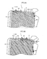
- each biosensor 3 has a constitution in which a cover 32 is attached to a substrate 30 via spacer 31.
- the biosensor 3 has a channel 33 formed therein between the substrate 30 and the cover 32. This channel 33 is communicated to the outside via a specimen introduction port 33a and an air release port 33b.
- the biosensor 3 further has provided therein two recesses 34 and 35 that each extend in the width direction of the substrate 30.
- the recess 34 is used when moving the biosensor 3 together with the operating belt 5 as described later with reference to FIG. 5 .
- the recess 35 is used when installing the biosensor 3 in the analyzer 2 as described later with reference to FIGS. 7C and D . Note that the recesses 34 and 35 penetrate through both the spacer 31 and the cover 32 here, but do not necessarily have to be formed so as to penetrate through both the spacer 31 and the cover 32.
- An upper surface 30a of the substrate 30 has provided thereon a working electrode 36, a counter electrode 37, a pair of detecting electrodes 38 (hereinafter these are sometimes referred to collectively as the 'electrodes 36 to 38'), and a reagent layer 39.
- the working electrode 36 and the counter electrode 37 are used, for example, for measuring the amount of electrons supplied from the reagent layer 39 as a response current when a fixed potential is applied to the reagent layer 39.
- the pair of detecting electrodes 38 are used to judge whether or not blood has been introduced into the channel 33 of the biosensor 3.
- One end portion 36a, 37a or 38a of each of the electrodes 36 to 38 is not covered by the spacer 31 or the cover 32, but rather is exposed.
- These end portions 36a, 37a and 38a constitute terminal portions for contacting with terminals 28 of the analyzer 2, described later (see FIGS. 6 and 7 ).
- the reagent layer 39 is, for example, solid, and is formed so as to cover the electrodes 36 to 38.
- the reagent layer 39 comprises, for example, a relatively small amount of an oxidoreductase dispersed in a relatively large amount of a mediator (an electron transporter).
- An iron complex or a ruthenium complex can, for example, be used as the electron transporter.
- the oxidoreductase is selected in accordance with the type of the specific component that is to be subjected to the concentration measurement. Examples of the specific component include glucose, cholesterol and lactic acid.
- oxidoreductases for such specific components include glucose dehydrogenase, glucose oxidase, cholesterol dehydrogenase, cholesterol oxidase, lactic acid dehydrogenase, and lactic acid oxidase.
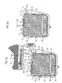
- the operating belt 5 has the form of a loop overall, and is stretched around an outer surface of the annular wall portion 45 of the first member 41.
- the operating belt 5 has thereon a knob 50, the pair of engaging claws 51, a closing portion 52, and an opening portion 53.
- the knob 50 is for moving (rotating) the operating belt 5 relative to the annular wall portion 45, and hence the case 4, along the outer surface of the annular wall portion 45.
- the pair of engaging claws 51 are passed through the slits 45a in the upper wall portion 45A of the annular wall portion 45, with ends thereof that project out through the slits 45a engaging into the recess 34 in a biosensor 3.
- the pair of engaging claws 51 move through the slits 45a, and at the same time move relative to the upper wall portion 45A.
- the biosensor 3 is also moved relative to the annular wall portion 45, and hence the case 4.
- the number and shape of the engaging claws 51 is not limited to being as in the example shown in the drawings, but rather design modification is possible.
- the closing portion 52 closes up the slit 46 in the annular wall portion 45 in a standby state (a state when a biosensor 3 is not to be retrieved).
- a standby state a state when a biosensor 3 is not to be retrieved.
- the opening portion 53 is for opening up the slit 46 in the annular wall portion 45 when the operating belt 5 is moved relative to the annular wall portion 45 as shown in FIG. 5B , i.e. when a biosensor 3 is moved.
- the biosensor 3 held in the storage space 43 can be discharged out from the storage space 43.
- the stopper 45b of the case 4 is positioned in the opening portion 53, and the stopper 45b and an edge defining the opening portion 53 interfere with one another through the movement of the operating belt 5, the movement of the operating belt 5 is restricted.
- the engaging claws 51 of the operating belt 5 are engaged in the recess 34 of the uppermost biosensor 3, and moreover the biosensor 3 is biased upward.
- the slit 46 in the case 4 is closed up by the closing portion 52 of the operating belt 5.
- the inside of the case 4 is kept airtight in the standby state.
- the knob 50 is operated and moved in the direction of the arrow B in the drawings, then the engaging claws 51 and the closing portion 52 move in the direction of the arrow B together with the knob 50.
- the operating belt 5 while being guided by the plurality of projections 47 on the case 4, moves (rotates) along the outer surface of the annular wall portion 45.
- the closing portion 52 moves away from the slit 46, and the opening portion 53 of the operating belt 5 comes to be positioned at the slit 46, whereby the storage space 43 is communicated to the outside.
- the engaging claws 51 are engaged in the recess 34 of the biosensor 3, upon the engaging claws 51 moving in the direction of the arrow B, the biosensor 3 also moves in the direction of the arrow B. Because the biosensors 3 are biased upward, and the slit 46 is opened up by the movement of the knob 50, one biosensor 3 only is discharged from the slit 46. At this time, because the biosensors 3 are biased upward in the case 4, all of the plurality of biosensors 3 move upward. the biosensor 3 has been completely discharged from the case 4, the knob 50 is then moved in the direction of the arrow A so as to move into the standby state shown in FIG. 5A . As a result, the engaging claws 51 of the operating belt 5 are engaged into the recess 34 of the biosensor 3 that is now uppermost, and hence the standby state is achieved.
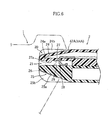
- the analyzer 2 is constituted, for example, so as to measure the concentration of a specific component in a specimen liquid supplied onto a biosensor 3 using an electrochemical method.
- This analyzer 2 comprises a holding portion 20 onto which the sensor cartridge 1 can be located and fixed, and an inserting portion 21 for inserting a biosensor 3, and also has a display 22 and operating buttons 23.
- the holding portion 20 is a portion onto which the notches 42A and 44A of the sensor cartridge 1 engage, and comprises a pair of recessed portions 24 and 25.
- These recessed portions 24 and 25 each have a tapering face 24a or 25a and guide faces 24b or 25b.
- the distance between the guide faces 24b or 25b of each of the recessed portions 24 and 25 spreads out toward the edge for a portion near to the edge, and corresponds to the distance between the second member 42 and the plate-shaped portion 44 of the first member 41 of the case 4 for a portion far from the edge.
- the slope of the tapering faces 24a and 25a of the recessed portions 24 and 25 corresponds to the slope of the tapering faces 42Ab and 44Ab of the notches 42A and 44A in the case 4.
- the inserting portion 21 is formed between the recessed portions 24 and 25 of the holding portion 20, and has therein a holding space 26 in which can be housed an end portion of a biosensor 3.
- a projection 27a that projects out downward is formed on an upper wall face 27 defining the holding space 26. This projection 27a fits into the recess 35 of the biosensor 3 when the biosensor 3 has been inserted into the holding space 26 as shown in FIGS. 7C and 7D .
- a plurality of terminals 28 (in the drawings only one terminal 28 is shown) extend out into the holding space 26.
- the plurality of, for example four, terminals 28 are disposed in positions corresponding to the end portions 36a to 38a of the electrodes 36 to 38.
- Each terminal 28 is biased downward. Consequently, when a biosensor 3 has been inserted into the holding space 26, the substrate 30 of the biosensor 3 is sandwiched between the terminals 28 and a lower wall face 29 defining the holding space 26. At this time, the plurality of terminals 28 contact the end portions 36a to 38a of the electrodes 36 to 38.
- a biosensor 3 is installed into the analyzer 2 using the sensor cartridge 1 through the following operations.
- the sensor cartridge 1 is located and fixed onto the analyzer 2. As described above, this locating and fixing is carried out by fitting the notches 42A and 44A of the sensor cartridge 1 onto the holding portion 20 of the analyzer 2. At this time, the slit 46 of the sensor cartridge 1 (the case 4) and the inserting portion 21 of the analyzer 2 are also aligned with one another.
- a biosensor 3 is discharged from the sensor cartridge 1 following the procedure described earlier with reference to FIGS. 5A and 5B , whereby the biosensor 3 is installed in the analyzer 2. More specifically, the knob 50 of the sensor cartridge 1 is moved in the direction of the arrow B by, for example, a manual operation of a user, whereby the biosensor 3 moves in the direction of the arrow B, and is discharged from the sensor cartridge 1. At this time, as shown in FIG. 7B , the biosensor 3 is inserted from an end portion 30b thereof into the inserting portion 21 of the analyzer 2. Upon moving the biosensor 3 further in the direction of the arrow B, as shown in FIG.
- concentration measurement with the analyzer 2 is carried out by supplying a specimen liquid onto the biosensor 3 via the specimen introduction port 33a.
- the specimen liquid introduced in from the specimen introduction port 33a travels through the channel 33 toward the air release port 33b.
- a specific component in the specimen liquid reacts with the reagent layer 39, and hence the mediator is reduced or oxidized.
- a voltage is applied to the reagent layer 39 via the end portions 36a and 37a, then electron transfer between the working electrode 36 and the mediator then takes place. The amount of this electron transfer is measured by the analyzer 2 using the working electrode 36 and the counter electrode 37.
- This amount of electron transfer correlates to the concentration of the specific component, and hence the concentration of the specific component can be calculated by measuring the amount of electron transfer.
- the detecting electrodes 38 by measuring the amount of electron transfer for these electrodes, it can be detected whether the specimen liquid has been supplied onto the biosensor 3.
- a biosensor 3 can be installed in the analyzer 2 merely by locating and fixing the sensor cartridge 1 onto the analyzer 2 and then moving the knob 50.
- the locating and fixing of the sensor cartridge 1 onto the analyzer 2 can be carried out easily utilizing the notches 42A and 44A of the sensor cartridge 1 and the recessed portions 24 and 25 of the analyzer 2, and moreover the operation of moving the knob 50 is also extremely easy.
- a biosensor 3 can be installed in the analyzer 2 through extremely simple operations, and hence a biosensor 3 can be installed with no problems even by people with failing eyesight or elderly people.
- the present invention is not limited to the present embodiment, but rather various design modifications are possible.
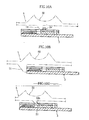
- an operating belt in the form of a loop instead of an operating belt in the form of a loop, an operating belt 5' in the form of a band may be used in a comparative example in FIGS. 9A and 9B (not forming an embodiment of the invention), the members for moving a biosensor 3 and the member for opening and closing the slit 46 in the case 4 may be formed as separate bodies.
- the operating belt 5' apart from the operating belt 5' being formed in the form of a band, the operating belt 5' has a similar constitution to the operating belt 5 described earlier; the operating belt 5' is provided so as to cover the slit 46 and the upper wall portion 45A of the annular wall portion 45.
- the two ends of the operating belt 5' are fixed to the annular wall portion 45 of the case 4 by coil springs B1 and B2.
- the slit 46 is closed up by a closing portion 52', and engaging claws 51' are engaged into the recess 34 of a biosensor 3.
- an operating belt 5" having a knob 50" and engaging claws 51" integrally molded thereon is fixed to the annular wall portion 45 of the case 4 by a spring B1.
- the slit 46 in the case 4 is closed up by a curtain 52". If the operating belt 5" is moved, then a biosensor 3 is pushed out from the case 4 while pushing the curtain 52" out of the way. If the force acting on the knob 50" is released, the operating belt 5" then automatically returns to its original position through the elastic force of the spring B1.
- FIGS. 10A to 10C show an example in which a projection 34' is provided on the biosensor 3, and the biosensor 3 is moved through the engaging claws 51 pushing the projection 34'
- FIG. 10B shows an example in which the biosensor 3 is moved through the engaging claws 51 pushing a rear end of the biosensor 3
- FIG. 10C shows an example in which the engaging claws 51 engage into the air release port 33b provided in the biosensor 3, and the biosensor 3 is moved in this state.
Landscapes
- Health & Medical Sciences (AREA)
- Engineering & Computer Science (AREA)
- Life Sciences & Earth Sciences (AREA)
- Biomedical Technology (AREA)
- Physics & Mathematics (AREA)
- Chemical & Material Sciences (AREA)
- Biochemistry (AREA)
- General Health & Medical Sciences (AREA)
- Molecular Biology (AREA)
- Urology & Nephrology (AREA)
- Optics & Photonics (AREA)
- Food Science & Technology (AREA)
- Hematology (AREA)
- Medicinal Chemistry (AREA)
- Biophysics (AREA)
- Analytical Chemistry (AREA)
- General Physics & Mathematics (AREA)
- Immunology (AREA)
- Pathology (AREA)
- Investigating Or Analysing Biological Materials (AREA)
- Automatic Analysis And Handling Materials Therefor (AREA)
- Sampling And Sample Adjustment (AREA)
Claims (16)
- Cartouche d'outils analytiques comprenant : un boîtier (4) comportant un espace de rangement (43) et un orifice d'extraction (46) qui met en communication l'espace de rangement (43) avec un espace externe ; et une pluralité d'outils analytiques (3) rangés dans l'espace de rangement (43) dans un état empilé ;
la cartouche d'outils analytiques comprenant en outre un mécanisme d'extraction pour extraire un à la fois les outils analytiques (3) du boîtier (4) via l'orifice d'extraction (46), et un mécanisme d'ouverture/fermeture (52, 53) pour ouvrir et fermer l'orifice d'extraction (46);
dans lequel le mécanisme d'extraction et le mécanisme d'ouverture/fermeture (52, 53) sont constitués à partir d'un même corps de manoeuvre (5),
dans lequel le corps de manoeuvre (5) comprend une protubérance de mise en prise (51) pour déplacer intégralement chacun des outils analytiques (3) lorsque le corps de manoeuvre (5) est déplacé dans un sens spécifique à partir d'un état de veille, une partie de manoeuvre (50) pour appliquer une charge au corps de manoeuvre (5) et ainsi le déplacer, une partie de fermeture (52) pour fermer l'orifice d'extraction (46) dans l'état de veille, et une partie d'ouverture (53) pour ouvrir l'orifice d'extraction (46) lorsque le corps de manoeuvre (5) est déplacé dans le sens spécifique depuis l'état de veille ;
dans lequel le corps de manoeuvre (5) est une courroie de manoeuvre sur laquelle la protubérance de mise en prise (51), la partie de fermeture (52) et la partie d'ouverture (53) sont tous formées, la partie de fermeture (52) étant agencée pour s'écarter de l'orifice d'extraction (46) avec la partie d'ouverture (53) positionnée au niveau de l'orifice d'extraction (46) en réponse au déplacement de la courroie de manoeuvre (5) dans ledit sens spécifique depuis l'état de veille ;
caractérisé en ce que le boîtier (4) comporte une partie de paroi annulaire (45) qui définit l'espace de rangement (43) et dans laquelle est fourni l'orifice d'extraction (46),
la courroie de manoeuvre (5) est disposée le long d'une surface externe de la partie de paroi annulaire (45) et est déplaçable par rapport à la partie de paroi annulaire (45), et
la partie d'ouverture (53) pénètre à travers la courroie de manoeuvre (5). - Cartouche d'outils analytiques selon la revendication 1, dans laquelle la courroie de manoeuvre (5) est formée en boucle.
- Cartouche d'outils analytiques selon la revendication 1, dans laquelle les outils analytiques (3) comprennent chacun une partie de mise en prise (34) avec laquelle la protubérance de mise en prise (51) se met en prise.
- Cartouche d'outils analytiques selon la revendication 1, dans laquelle l'espace de rangement (43) renferme un dessicant.
- Cartouche d'outils analytiques selon la revendication 4, dans laquelle les outils analytiques (3) sont rangés dans l'espace de rangement (43) dans un état supporté par une plate-forme (49), le dessicant étant fixé à la plate-forme (49).
- Cartouche d'outils analytiques selon la revendication 1, dans laquelle les outils analytiques (3) sont rangés dans l'espace de rangement (43) dans un état supporté et chargé préliminairement par une plate-forme (49).
- Cartouche d'outils analytiques selon la revendication 1, dans laquelle le boîtier (4) est doté d'une partie de guidage pour guider le corps de manoeuvre (5) quand le corps de manoeuvre (5) est déplacé.
- Cartouche d'outils analytiques selon la revendication 1, dans laquelle dans l'espace de rangement (43) par-dessus les outils analytiques (3) est empilée une puce de production d'informations à partir de laquelle peuvent être produites des informations relatives aux propriétés des outils analytiques (3).
- Cartouche d'outils analytiques selon la revendication 8, dans laquelle la puce de production d'informations sert à produire des informations relatives à une courbe d'étalonnage.
- Ensemble de cartouche d'outils analytiques (1) selon l'une quelconque des revendications 1 à 9 et d'analyseur (2),
dans lequel l'analyseur (2) est adapté pour recevoir un outil analytique extrait de la cartouche d'outils analytiques (1) pour analyser un composant spécifique dans un échantillon de liquide placé sur l'outil analytique. - Ensemble selon la revendication 10, dans lequel au moins l'un de la cartouche d'outils analytiques (1) et de l'analyseur (2) est doté d'un moyen de fixation de cartouche (20, 42A, 44A) pour positionner et fixer la cartouche d'outils analytiques (1) sur l'analyseur (2).
- Ensemble selon la revendication 11, dans lequel le moyen de fixation de cartouche (20, 42A, 44A) comporte des premières faces d'arrêt (24b, 25b) pour limiter le mouvement de la cartouche d'outils analytiques (1) dans un sens orthogonal à chacun d'un sens d'empilage des outils analytiques (3) et d'un sens d'insertion des outils analytiques (3), et des secondes faces d'arrêt (42Ab, 44Ab) pour limiter le mouvement de la cartouche d'outils analytiques (1) dans le sens d'empilage des outils analytiques (3).
- Ensemble selon la revendication 12, dans lequel les premières faces d'arrêt (24b ,25b) sont fournies sur l'analyseur (2), les secondes faces d'arrêt (42Ab, 44Ab) étant fournies sur la cartouche d'outils analytiques (1).
- Ensemble selon la revendication 13, dans lequel le moyen de fixation de cartouche comprend des encoches (42A, 44A) fournies dans le boîtier (4), et des parties évidées (24, 25) fournies dans l'analyseur (2).
- Ensemble selon la revendication 10, dans lequel l'analyseur (2) comporte une partie d'insertion (21) dans laquelle une partie d'extrémité de l'outil analytique (3) est insérée, la partie d'insertion (21) étant dotée d'un moyen de fixation d'outil analytique (27a) pour fixer l'outil analytique dans l'analyseur (2).
- Ensemble selon la revendication 15, dans lequel le moyen de fixation d'outil analytique comprend une protubérance (27a) fournie sur la partie d'insertion (21), et un évidement (25) est fourni sur l'outil analytique (3) en vue de la mise en prise avec la protubérance (27a).
Applications Claiming Priority (3)
| Application Number | Priority Date | Filing Date | Title |
|---|---|---|---|
| JP2002104274A JP4143753B2 (ja) | 2002-04-05 | 2002-04-05 | 取り出し機構を備えた分析用具カートリッジ、およびこれと分析装置のセット |
| JP2002104274 | 2002-04-05 | ||
| PCT/JP2003/004373 WO2003085392A1 (fr) | 2002-04-05 | 2003-04-04 | Cartouche de dispositif analytique dotee d'un mecanisme d'extraction et reglage de la cartouche et d'un analyseur |
Publications (3)
| Publication Number | Publication Date |
|---|---|
| EP1494021A1 EP1494021A1 (fr) | 2005-01-05 |
| EP1494021A4 EP1494021A4 (fr) | 2010-01-13 |
| EP1494021B1 true EP1494021B1 (fr) | 2015-01-14 |
Family
ID=28786336
Family Applications (1)
| Application Number | Title | Priority Date | Filing Date |
|---|---|---|---|
| EP03745930.2A Expired - Lifetime EP1494021B1 (fr) | 2002-04-05 | 2003-04-04 | Cartouche de dispositif analytique dotee d'un mecanisme d'extraction et un ensemble cartouche/analyseur |
Country Status (6)
| Country | Link |
|---|---|
| US (1) | US8052942B2 (fr) |
| EP (1) | EP1494021B1 (fr) |
| JP (1) | JP4143753B2 (fr) |
| CN (1) | CN100406878C (fr) |
| AU (1) | AU2003236277A1 (fr) |
| WO (1) | WO2003085392A1 (fr) |
Families Citing this family (26)
| Publication number | Priority date | Publication date | Assignee | Title |
|---|---|---|---|---|
| US7585464B2 (en) * | 2002-04-19 | 2009-09-08 | Panasonic Corporation | Biosensor cartridge and biosensor dispensing device |
| WO2005075979A1 (fr) * | 2004-02-04 | 2005-08-18 | Matsushita Electric Industrial Co., Ltd. | Biocapteur et dispositif et procede de mesure a biocapteur |
| US7819283B2 (en) * | 2004-02-18 | 2010-10-26 | Universal Biosensors Pty Ltd | Strip ejection system |
| CN101052881B (zh) * | 2004-10-29 | 2012-06-06 | 爱科来株式会社 | 分析装置、盒和分析套件 |
| JP2006170974A (ja) | 2004-12-15 | 2006-06-29 | F Hoffmann-La Roche Ag | 分析試験エレメント上での液体試料の分析用分析システム |
| DE102004060322A1 (de) * | 2004-12-15 | 2006-06-22 | Roche Diagnostics Gmbh | Analysesystem mit einem elektrischen Anschlusssystem für ein Testelement |
| WO2006076721A2 (fr) * | 2005-01-14 | 2006-07-20 | Bayer Healthcare Llc | Cartouches a capteurs test et instruments pour distribuer les capteurs |
| US8016154B2 (en) * | 2005-05-25 | 2011-09-13 | Lifescan, Inc. | Sensor dispenser device and method of use |
| US7858046B2 (en) | 2006-09-14 | 2010-12-28 | Bayer Healthcare Llc | Detachable test sensor container having a system for reducing coding errors |
| EP2088436B1 (fr) | 2006-11-06 | 2019-03-06 | ARKRAY, Inc. | Cartouche et système d'analyse |
| US9052305B2 (en) * | 2007-03-06 | 2015-06-09 | Lifescan, Inc. | Test strip dispenser |
| US8001825B2 (en) * | 2007-11-30 | 2011-08-23 | Lifescan, Inc. | Auto-calibrating metering system and method of use |
| TWM368068U (en) | 2009-06-19 | 2009-11-01 | Apex Biotechnology Corp | Holding device for medical test strip |
| CN101846686A (zh) * | 2009-12-10 | 2010-09-29 | 金薇 | 自动校正连续测试弹匣式血糖仪及配套试条 |
| JP5494272B2 (ja) * | 2010-06-18 | 2014-05-14 | 大日本印刷株式会社 | 板状物収納容器 |
| JP5516289B2 (ja) * | 2010-09-30 | 2014-06-11 | 大日本印刷株式会社 | グルコース濃度測定器システム、グルコースセンサチップ携行ケース |
| US9924892B2 (en) * | 2011-05-31 | 2018-03-27 | Tara Chand Singhal | Integrated blood glucose measuring device |
| EP3023785B1 (fr) | 2011-12-20 | 2017-05-10 | Ascensia Diabetes Care Holdings AG | Dispositif de mesure d'analytes stockant capteurs de test dans compartiments pliables |
| EP2618144A1 (fr) * | 2012-01-18 | 2013-07-24 | Medical Device UG | Procédé et récipient de chargement d'un appareil de mesure doté d'unités de moyens de mesure |
| KR101161322B1 (ko) * | 2012-01-13 | 2012-07-02 | 주식회사 아이센스 | 바이오센서와 이의 측정기를 연결하는 커넥터 |
| WO2013118609A1 (fr) * | 2012-02-08 | 2013-08-15 | キタノ製作株式会社 | Boîtier à capteurs |
| TW201347314A (zh) * | 2012-05-08 | 2013-11-16 | Actherm Inc | 電氣連接器及具有試片的電氣連接器 |
| US9204829B2 (en) | 2012-05-31 | 2015-12-08 | Bayer Healthcare Llc | Multistrip cartridge |
| CA2872191C (fr) | 2012-05-31 | 2018-05-22 | Bayer Healthcare Llc | Cartouche a multibande remplacable et dispositif de mesure a biocapteur |
| US10533949B2 (en) | 2013-03-12 | 2020-01-14 | Ascensia Diabetes Care Holdings Ag | Test strip meter with a mechanism for pushing the test strip against an optical reader |
| JP2014081389A (ja) * | 2014-02-10 | 2014-05-08 | Dainippon Printing Co Ltd | グルコース濃度測定器システム、グルコース濃度測定メータ |
Family Cites Families (25)
| Publication number | Priority date | Publication date | Assignee | Title |
|---|---|---|---|---|
| US3918910A (en) * | 1973-07-31 | 1975-11-11 | Olympus Optical Co | System for detecting the particular chemical constituent of a fluid |
| US4911344A (en) | 1988-03-23 | 1990-03-27 | Tek-Aids Inc. | Strip dispenser box |
| US5320732A (en) | 1990-07-20 | 1994-06-14 | Matsushita Electric Industrial Co., Ltd. | Biosensor and measuring apparatus using the same |
| JPH0810208B2 (ja) | 1990-07-20 | 1996-01-31 | 松下電器産業株式会社 | バイオセンサおよびバイオセンサ測定装置 |
| DE4205805A1 (de) * | 1992-02-26 | 1993-09-02 | Sanner Friedr Gmbh Co Kg | Spende-behaelter fuer streifenfoermige materialabschnitte |
| GB9223016D0 (en) * | 1992-11-03 | 1992-12-16 | Environmental And Medical Prod | Electrochemical sensor |
| FR2701117B1 (fr) | 1993-02-04 | 1995-03-10 | Asulab Sa | Système de mesures électrochimiques à capteur multizones, et son application au dosage du glucose. |
| JPH0894630A (ja) * | 1994-09-21 | 1996-04-12 | Fuji Photo Film Co Ltd | 生化学分析装置 |
| US5630986A (en) | 1995-01-13 | 1997-05-20 | Bayer Corporation | Dispensing instrument for fluid monitoring sensors |
| JPH09250998A (ja) * | 1996-03-14 | 1997-09-22 | Daikin Ind Ltd | 濃度測定装置 |
| WO1998019159A1 (fr) * | 1996-10-30 | 1998-05-07 | Mercury Diagnostics, Inc. | Systeme d'essai synchronise de l'analysat |
| JPH10253570A (ja) * | 1997-03-14 | 1998-09-25 | Daikin Ind Ltd | 濃度測定装置 |
| FI107080B (fi) * | 1997-10-27 | 2001-05-31 | Nokia Mobile Phones Ltd | Mittauslaite |
| DE19755529A1 (de) | 1997-12-13 | 1999-06-17 | Roche Diagnostics Gmbh | Analysensystem für Probenflüssigkeiten |
| EP1118856A4 (fr) * | 1998-09-29 | 2008-07-23 | Omron Healthcare Co Ltd | Systeme d'analyse des composants d'un echantillon, et puce de detection et ensemble de detection utilises dans ce systeme |
| JP4471425B2 (ja) * | 1999-11-18 | 2010-06-02 | パナソニック株式会社 | センサ供給装置 |
| WO2001063272A1 (fr) | 2000-02-23 | 2001-08-30 | Arkray, Inc. | Cartouche de capteur, dispositif d'alimentation de capteur, et instrument de mesure |
| JP4430195B2 (ja) * | 2000-03-30 | 2010-03-10 | パナソニック株式会社 | 測定システム |
| US6413213B1 (en) * | 2000-04-18 | 2002-07-02 | Roche Diagnostics Corporation | Subscription based monitoring system and method |
| GB0017737D0 (en) * | 2000-07-20 | 2000-09-06 | Hypoguard Limited | Test device |
| GB0021219D0 (en) * | 2000-08-30 | 2000-10-18 | Hypoguard Ltd | Test device |
| US7063234B2 (en) * | 2000-12-29 | 2006-06-20 | Csp Technologies, Inc. | Meter strip dispenser assembly |
| JP4570290B2 (ja) | 2001-08-01 | 2010-10-27 | パナソニック株式会社 | バイオセンサカートリッジ及びバイオセンサ分与装置 |
| US7723113B2 (en) | 2001-08-20 | 2010-05-25 | Bayer Healthcare Llc | Packaging system for test sensors |
| JP4357449B2 (ja) | 2005-04-26 | 2009-11-04 | 株式会社ルネサステクノロジ | 録画再生装置の制御方法 |
-
2002
- 2002-04-05 JP JP2002104274A patent/JP4143753B2/ja not_active Expired - Lifetime
-
2003
- 2003-04-04 US US10/511,588 patent/US8052942B2/en active Active
- 2003-04-04 WO PCT/JP2003/004373 patent/WO2003085392A1/fr not_active Ceased
- 2003-04-04 AU AU2003236277A patent/AU2003236277A1/en not_active Abandoned
- 2003-04-04 EP EP03745930.2A patent/EP1494021B1/fr not_active Expired - Lifetime
- 2003-04-04 CN CN038077051A patent/CN100406878C/zh not_active Expired - Lifetime
Also Published As
| Publication number | Publication date |
|---|---|
| US8052942B2 (en) | 2011-11-08 |
| JP2003302314A (ja) | 2003-10-24 |
| CN100406878C (zh) | 2008-07-30 |
| CN1646898A (zh) | 2005-07-27 |
| JP4143753B2 (ja) | 2008-09-03 |
| EP1494021A1 (fr) | 2005-01-05 |
| US20050186162A1 (en) | 2005-08-25 |
| WO2003085392A1 (fr) | 2003-10-16 |
| EP1494021A4 (fr) | 2010-01-13 |
| AU2003236277A1 (en) | 2003-10-20 |
Similar Documents
| Publication | Publication Date | Title |
|---|---|---|
| EP1494021B1 (fr) | Cartouche de dispositif analytique dotee d'un mecanisme d'extraction et un ensemble cartouche/analyseur | |
| JP2009525794A (ja) | 交換可能な試験片カートリッジを備える個人用の携帯式血中グルコース測定器 | |
| US5556533A (en) | Voltage applying method for hydrogen-type enzyme electrode | |
| EP1369686B1 (fr) | Dispositifs pour la détermination de la concentration d'un analyte et leur utilisation | |
| EP1500925B1 (fr) | Cartouche de biocapteurs et dispositif distributeur de biocapteurs | |
| EP1329395A1 (fr) | Distributeur de bandelette d'essai | |
| US20030089730A1 (en) | Sensor dispensing device | |
| JPH11242024A (ja) | 液体試料の分析系 | |
| EP1444512A1 (fr) | Dispositif de distribution de capteurs | |
| JP4570290B2 (ja) | バイオセンサカートリッジ及びバイオセンサ分与装置 | |
| EP3158329B1 (fr) | Pince pour capteurs pour système de distribution de capteurs empilés et système utilisant celle-ci | |
| US20090008246A1 (en) | Cartridge for Containing and Dispensing Test Sensors | |
| JP6562924B2 (ja) | 検査ストリップコネクタの接触保護 | |
| US9081000B2 (en) | Cartridge for body fluid measuring strips and a body fluid measurement device | |
| KR20150095796A (ko) | 전기화학 센서를 위한 디스펜서 | |
| CN101568839B (zh) | 试剂盒及分析系统 | |
| JP2009022675A (ja) | バイオセンサカートリッジ |
Legal Events
| Date | Code | Title | Description |
|---|---|---|---|
| PUAI | Public reference made under article 153(3) epc to a published international application that has entered the european phase |
Free format text: ORIGINAL CODE: 0009012 |
|
| 17P | Request for examination filed |
Effective date: 20041014 |
|
| AK | Designated contracting states |
Kind code of ref document: A1 Designated state(s): AT BE BG CH CY CZ DE DK EE ES FI FR GB GR HU IE IT LI LU MC NL PT RO SE SI SK TR |
|
| AX | Request for extension of the european patent |
Extension state: AL LT LV MK |
|
| A4 | Supplementary search report drawn up and despatched |
Effective date: 20091214 |
|
| 17Q | First examination report despatched |
Effective date: 20100210 |
|
| REG | Reference to a national code |
Ref country code: DE Ref legal event code: R079 Ref document number: 60347226 Country of ref document: DE Free format text: PREVIOUS MAIN CLASS: G01N0027280000 Ipc: G01N0033487000 |
|
| GRAP | Despatch of communication of intention to grant a patent |
Free format text: ORIGINAL CODE: EPIDOSNIGR1 |
|
| RIC1 | Information provided on ipc code assigned before grant |
Ipc: G01N 33/487 20060101AFI20140718BHEP |
|
| INTG | Intention to grant announced |
Effective date: 20140807 |
|
| GRAS | Grant fee paid |
Free format text: ORIGINAL CODE: EPIDOSNIGR3 |
|
| GRAA | (expected) grant |
Free format text: ORIGINAL CODE: 0009210 |
|
| AK | Designated contracting states |
Kind code of ref document: B1 Designated state(s): AT BE BG CH CY CZ DE DK EE ES FI FR GB GR HU IE IT LI LU MC NL PT RO SE SI SK TR |
|
| REG | Reference to a national code |
Ref country code: GB Ref legal event code: FG4D |
|
| REG | Reference to a national code |
Ref country code: CH Ref legal event code: EP |
|
| REG | Reference to a national code |
Ref country code: IE Ref legal event code: FG4D |
|
| REG | Reference to a national code |
Ref country code: AT Ref legal event code: REF Ref document number: 707318 Country of ref document: AT Kind code of ref document: T Effective date: 20150215 |
|
| REG | Reference to a national code |
Ref country code: DE Ref legal event code: R096 Ref document number: 60347226 Country of ref document: DE Effective date: 20150226 |
|
| REG | Reference to a national code |
Ref country code: NL Ref legal event code: VDEP Effective date: 20150114 |
|
| REG | Reference to a national code |
Ref country code: AT Ref legal event code: MK05 Ref document number: 707318 Country of ref document: AT Kind code of ref document: T Effective date: 20150114 |
|
| PG25 | Lapsed in a contracting state [announced via postgrant information from national office to epo] |
Ref country code: BG Free format text: LAPSE BECAUSE OF FAILURE TO SUBMIT A TRANSLATION OF THE DESCRIPTION OR TO PAY THE FEE WITHIN THE PRESCRIBED TIME-LIMIT Effective date: 20150414 Ref country code: FI Free format text: LAPSE BECAUSE OF FAILURE TO SUBMIT A TRANSLATION OF THE DESCRIPTION OR TO PAY THE FEE WITHIN THE PRESCRIBED TIME-LIMIT Effective date: 20150114 Ref country code: SE Free format text: LAPSE BECAUSE OF FAILURE TO SUBMIT A TRANSLATION OF THE DESCRIPTION OR TO PAY THE FEE WITHIN THE PRESCRIBED TIME-LIMIT Effective date: 20150114 Ref country code: ES Free format text: LAPSE BECAUSE OF FAILURE TO SUBMIT A TRANSLATION OF THE DESCRIPTION OR TO PAY THE FEE WITHIN THE PRESCRIBED TIME-LIMIT Effective date: 20150114 |
|
| RAP2 | Party data changed (patent owner data changed or rights of a patent transferred) |
Owner name: ARKRAY, INC. |
|
| PG25 | Lapsed in a contracting state [announced via postgrant information from national office to epo] |
Ref country code: AT Free format text: LAPSE BECAUSE OF FAILURE TO SUBMIT A TRANSLATION OF THE DESCRIPTION OR TO PAY THE FEE WITHIN THE PRESCRIBED TIME-LIMIT Effective date: 20150114 Ref country code: GR Free format text: LAPSE BECAUSE OF FAILURE TO SUBMIT A TRANSLATION OF THE DESCRIPTION OR TO PAY THE FEE WITHIN THE PRESCRIBED TIME-LIMIT Effective date: 20150415 Ref country code: NL Free format text: LAPSE BECAUSE OF FAILURE TO SUBMIT A TRANSLATION OF THE DESCRIPTION OR TO PAY THE FEE WITHIN THE PRESCRIBED TIME-LIMIT Effective date: 20150114 |
|
| REG | Reference to a national code |
Ref country code: DE Ref legal event code: R097 Ref document number: 60347226 Country of ref document: DE |
|
| PG25 | Lapsed in a contracting state [announced via postgrant information from national office to epo] |
Ref country code: DK Free format text: LAPSE BECAUSE OF FAILURE TO SUBMIT A TRANSLATION OF THE DESCRIPTION OR TO PAY THE FEE WITHIN THE PRESCRIBED TIME-LIMIT Effective date: 20150114 Ref country code: CZ Free format text: LAPSE BECAUSE OF FAILURE TO SUBMIT A TRANSLATION OF THE DESCRIPTION OR TO PAY THE FEE WITHIN THE PRESCRIBED TIME-LIMIT Effective date: 20150114 Ref country code: SK Free format text: LAPSE BECAUSE OF FAILURE TO SUBMIT A TRANSLATION OF THE DESCRIPTION OR TO PAY THE FEE WITHIN THE PRESCRIBED TIME-LIMIT Effective date: 20150114 Ref country code: RO Free format text: LAPSE BECAUSE OF FAILURE TO SUBMIT A TRANSLATION OF THE DESCRIPTION OR TO PAY THE FEE WITHIN THE PRESCRIBED TIME-LIMIT Effective date: 20150114 Ref country code: EE Free format text: LAPSE BECAUSE OF FAILURE TO SUBMIT A TRANSLATION OF THE DESCRIPTION OR TO PAY THE FEE WITHIN THE PRESCRIBED TIME-LIMIT Effective date: 20150114 |
|
| PLBE | No opposition filed within time limit |
Free format text: ORIGINAL CODE: 0009261 |
|
| STAA | Information on the status of an ep patent application or granted ep patent |
Free format text: STATUS: NO OPPOSITION FILED WITHIN TIME LIMIT |
|
| PG25 | Lapsed in a contracting state [announced via postgrant information from national office to epo] |
Ref country code: MC Free format text: LAPSE BECAUSE OF FAILURE TO SUBMIT A TRANSLATION OF THE DESCRIPTION OR TO PAY THE FEE WITHIN THE PRESCRIBED TIME-LIMIT Effective date: 20150114 Ref country code: LU Free format text: LAPSE BECAUSE OF FAILURE TO SUBMIT A TRANSLATION OF THE DESCRIPTION OR TO PAY THE FEE WITHIN THE PRESCRIBED TIME-LIMIT Effective date: 20150404 |
|
| REG | Reference to a national code |
Ref country code: CH Ref legal event code: PL |
|
| 26N | No opposition filed |
Effective date: 20151015 |
|
| REG | Reference to a national code |
Ref country code: IE Ref legal event code: MM4A |
|
| PG25 | Lapsed in a contracting state [announced via postgrant information from national office to epo] |
Ref country code: CH Free format text: LAPSE BECAUSE OF NON-PAYMENT OF DUE FEES Effective date: 20150430 Ref country code: LI Free format text: LAPSE BECAUSE OF NON-PAYMENT OF DUE FEES Effective date: 20150430 |
|
| PG25 | Lapsed in a contracting state [announced via postgrant information from national office to epo] |
Ref country code: SI Free format text: LAPSE BECAUSE OF FAILURE TO SUBMIT A TRANSLATION OF THE DESCRIPTION OR TO PAY THE FEE WITHIN THE PRESCRIBED TIME-LIMIT Effective date: 20150114 |
|
| REG | Reference to a national code |
Ref country code: FR Ref legal event code: PLFP Year of fee payment: 14 |
|
| PG25 | Lapsed in a contracting state [announced via postgrant information from national office to epo] |
Ref country code: IE Free format text: LAPSE BECAUSE OF NON-PAYMENT OF DUE FEES Effective date: 20150404 |
|
| PG25 | Lapsed in a contracting state [announced via postgrant information from national office to epo] |
Ref country code: BE Free format text: LAPSE BECAUSE OF FAILURE TO SUBMIT A TRANSLATION OF THE DESCRIPTION OR TO PAY THE FEE WITHIN THE PRESCRIBED TIME-LIMIT Effective date: 20150114 |
|
| REG | Reference to a national code |
Ref country code: FR Ref legal event code: PLFP Year of fee payment: 15 |
|
| PG25 | Lapsed in a contracting state [announced via postgrant information from national office to epo] |
Ref country code: HU Free format text: LAPSE BECAUSE OF FAILURE TO SUBMIT A TRANSLATION OF THE DESCRIPTION OR TO PAY THE FEE WITHIN THE PRESCRIBED TIME-LIMIT; INVALID AB INITIO Effective date: 20030404 |
|
| PG25 | Lapsed in a contracting state [announced via postgrant information from national office to epo] |
Ref country code: CY Free format text: LAPSE BECAUSE OF FAILURE TO SUBMIT A TRANSLATION OF THE DESCRIPTION OR TO PAY THE FEE WITHIN THE PRESCRIBED TIME-LIMIT Effective date: 20150114 |
|
| PG25 | Lapsed in a contracting state [announced via postgrant information from national office to epo] |
Ref country code: PT Free format text: LAPSE BECAUSE OF FAILURE TO SUBMIT A TRANSLATION OF THE DESCRIPTION OR TO PAY THE FEE WITHIN THE PRESCRIBED TIME-LIMIT Effective date: 20150514 |
|
| PG25 | Lapsed in a contracting state [announced via postgrant information from national office to epo] |
Ref country code: TR Free format text: LAPSE BECAUSE OF FAILURE TO SUBMIT A TRANSLATION OF THE DESCRIPTION OR TO PAY THE FEE WITHIN THE PRESCRIBED TIME-LIMIT Effective date: 20150114 |
|
| REG | Reference to a national code |
Ref country code: FR Ref legal event code: PLFP Year of fee payment: 16 |
|
| PGFP | Annual fee paid to national office [announced via postgrant information from national office to epo] |
Ref country code: IT Payment date: 20220420 Year of fee payment: 20 Ref country code: GB Payment date: 20220420 Year of fee payment: 20 Ref country code: FR Payment date: 20220420 Year of fee payment: 20 Ref country code: DE Payment date: 20220420 Year of fee payment: 20 |
|
| REG | Reference to a national code |
Ref country code: DE Ref legal event code: R071 Ref document number: 60347226 Country of ref document: DE |
|
| REG | Reference to a national code |
Ref country code: GB Ref legal event code: PE20 Expiry date: 20230403 |
|
| PG25 | Lapsed in a contracting state [announced via postgrant information from national office to epo] |
Ref country code: GB Free format text: LAPSE BECAUSE OF EXPIRATION OF PROTECTION Effective date: 20230403 |