EP1494323A1 - Procédé de fabrication d'éléments electriquement conducteurs isolés de collecteur tournant et collecteur tournant comportant ces éléments electriquement conducteurs - Google Patents
Procédé de fabrication d'éléments electriquement conducteurs isolés de collecteur tournant et collecteur tournant comportant ces éléments electriquement conducteurs Download PDFInfo
- Publication number
- EP1494323A1 EP1494323A1 EP04291564A EP04291564A EP1494323A1 EP 1494323 A1 EP1494323 A1 EP 1494323A1 EP 04291564 A EP04291564 A EP 04291564A EP 04291564 A EP04291564 A EP 04291564A EP 1494323 A1 EP1494323 A1 EP 1494323A1
- Authority
- EP
- European Patent Office
- Prior art keywords
- zone
- electrically conductive
- enamel
- collector
- conductive elements
- Prior art date
- Legal status (The legal status is an assumption and is not a legal conclusion. Google has not performed a legal analysis and makes no representation as to the accuracy of the status listed.)
- Granted
Links
Images

Classifications
-
- H—ELECTRICITY
- H01—ELECTRIC ELEMENTS
- H01R—ELECTRICALLY-CONDUCTIVE CONNECTIONS; STRUCTURAL ASSOCIATIONS OF A PLURALITY OF MUTUALLY-INSULATED ELECTRICAL CONNECTING ELEMENTS; COUPLING DEVICES; CURRENT COLLECTORS
- H01R39/00—Rotary current collectors, distributors or interrupters
- H01R39/02—Details for dynamo electric machines
- H01R39/38—Brush holders
- H01R39/39—Brush holders wherein the brush is fixedly mounted in the holder
-
- H—ELECTRICITY
- H01—ELECTRIC ELEMENTS
- H01R—ELECTRICALLY-CONDUCTIVE CONNECTIONS; STRUCTURAL ASSOCIATIONS OF A PLURALITY OF MUTUALLY-INSULATED ELECTRICAL CONNECTING ELEMENTS; COUPLING DEVICES; CURRENT COLLECTORS
- H01R4/00—Electrically-conductive connections between two or more conductive members in direct contact, i.e. touching one another; Means for effecting or maintaining such contact; Electrically-conductive connections having two or more spaced connecting locations for conductors and using contact members penetrating insulation
- H01R4/70—Insulation of connections
-
- Y—GENERAL TAGGING OF NEW TECHNOLOGICAL DEVELOPMENTS; GENERAL TAGGING OF CROSS-SECTIONAL TECHNOLOGIES SPANNING OVER SEVERAL SECTIONS OF THE IPC; TECHNICAL SUBJECTS COVERED BY FORMER USPC CROSS-REFERENCE ART COLLECTIONS [XRACs] AND DIGESTS
- Y10—TECHNICAL SUBJECTS COVERED BY FORMER USPC
- Y10T—TECHNICAL SUBJECTS COVERED BY FORMER US CLASSIFICATION
- Y10T29/00—Metal working
- Y10T29/49—Method of mechanical manufacture
- Y10T29/49002—Electrical device making
- Y10T29/49009—Dynamoelectric machine
-
- Y—GENERAL TAGGING OF NEW TECHNOLOGICAL DEVELOPMENTS; GENERAL TAGGING OF CROSS-SECTIONAL TECHNOLOGIES SPANNING OVER SEVERAL SECTIONS OF THE IPC; TECHNICAL SUBJECTS COVERED BY FORMER USPC CROSS-REFERENCE ART COLLECTIONS [XRACs] AND DIGESTS
- Y10—TECHNICAL SUBJECTS COVERED BY FORMER USPC
- Y10T—TECHNICAL SUBJECTS COVERED BY FORMER US CLASSIFICATION
- Y10T29/00—Metal working
- Y10T29/49—Method of mechanical manufacture
- Y10T29/49002—Electrical device making
- Y10T29/49117—Conductor or circuit manufacturing
- Y10T29/49169—Assembling electrical component directly to terminal or elongated conductor
-
- Y—GENERAL TAGGING OF NEW TECHNOLOGICAL DEVELOPMENTS; GENERAL TAGGING OF CROSS-SECTIONAL TECHNOLOGIES SPANNING OVER SEVERAL SECTIONS OF THE IPC; TECHNICAL SUBJECTS COVERED BY FORMER USPC CROSS-REFERENCE ART COLLECTIONS [XRACs] AND DIGESTS
- Y10—TECHNICAL SUBJECTS COVERED BY FORMER USPC
- Y10T—TECHNICAL SUBJECTS COVERED BY FORMER US CLASSIFICATION
- Y10T29/00—Metal working
- Y10T29/49—Method of mechanical manufacture
- Y10T29/49002—Electrical device making
- Y10T29/49117—Conductor or circuit manufacturing
- Y10T29/49204—Contact or terminal manufacturing
- Y10T29/49208—Contact or terminal manufacturing by assembling plural parts
- Y10T29/4921—Contact or terminal manufacturing by assembling plural parts with bonding
- Y10T29/49211—Contact or terminal manufacturing by assembling plural parts with bonding of fused material
Definitions
- the invention relates to a manufacturing method of insulated electrically conductive elements of collector rotating and a rotating collector for the field space comprising these electrically conductive elements.
- Rotary manifolds are used to transfer electrical power or signals between parts moving relative to each other. They understand generally a fixed carrier structure, called a stator, supporting conductive wires called eyelashes, and a part rotating, the rotor, carrying a plurality of tracks cylindrical conductors on which the ends of the eyelashes are in electrical contact. Eyelashes on the one hand, tracks on the other hand, are connected to drivers electrical devices through which power or signals.
- the conductive threads or eyelashes are generally in copper, gold, platinum, copper alloy, alloy gold or platinum alloy.
- the power or electrical signals are transferred from the fixed part to the moving part by brushes rubbing with a track cylindrical or flat conductor. These brooms are mounted on flexible brush holders.
- the eyelashes and the brush holders constitute electrically conductive elements within the meaning of this invention. Since they are drivers, they must be isolated from each other. This isolation is currently performed by spacing the eyelashes or Brush holders between them. This solution presents the disadvantage of being sensitive to pollution by particles or by a conductive plasma that can cause short circuits between eyelashes or brush holders neighbors. In the space domain to which the invention applies, such risks are not eligible given the required reliability.
- DE-1,613,183 discloses elastic arms. At their end is brazed pad in rubbing contact on a conductive track.
- the elastic element is constituted by the conductor itself which is surrounded by an insulating sheath of flexible synthetic material.
- an insulating sheath of flexible synthetic material usually of the order of 100 .mu.m.
- the present invention relates to a method of manufacture of insulated electrically conductive elements, particularly eyelashes and broom mounts collector and a rotating collector comprising these eyelashes and / or these brush holders that remedy this disadvantage.
- an electrically conductive element for transferring a electrical current between two moving parts one by report to the other.
- This electrically conductive element is covered with at least one layer of insulating enamel electrically, except for a zone of continuity electric.
- the electrical continuity zone is a friction zone in contact with a track driver who moves in relation to him.
- the electrical continuity zone is a zone for assembling the brushes, which are in contact with a conductive track that moves relative to them.
- the electrically conductive elements are mounted on a carrier structure of the collector after the step (c) of treatment of the electrical continuity zone.
- the electrically conductive elements are mounted on a carrier structure of the collector before the step (c) of treatment of the electrical continuity zone.
- the enamel layer or layers are chosen in the group comprising polyvinyls, polyurethanes, polyesters, polyesterimides, polyamide imides, polyimides.
- the electrically conductive element may comprise several layers of enamel of the same chemical nature or of different natures.
- the invention also relates to a collector comprising a first part and a second part moving one by to the other, one of those parts supporting a plurality of electrically conductive elements made according to the method of the invention. Electrically elements conductors are covered with at least one layer of enamel electrically insulating with the exception of a zone zone electrical continuity.
- the collector comprises a fixed support structure and a rotor comprising conductive tracks and rotatably mounted in the structure carrier, the supporting structure supporting a plurality of electrically conductive lashes each having a zone of contact applied on a rotor track.
- the collector comprises a fixed support structure and a rotor comprising cylindrical or flat conductive tracks and mounted rotating in the supporting structure, the supporting structure supporting a plurality of brush holders electrically conductive having each a mounting zone brushes in contact on a rotor track.
- the collector shown in FIGS. 1 and 2 comprises a fixed support structure 2 which supports two supports of eyelashes 8.
- Eyelashes 14 comprise a flat portion 15 maintained in an eyelash holder 8 by a lid or by a resin filling and two free ends 20 disposed on either side of the flat part 15.
- the eyelashes are copper or copper alloy, or other good metals drivers like gold, silver, platinum or any of their alloys.
- the eyelashes 14 are in gold alloy and have a circular section. However, he is understood that in the context of the invention they may have another section, for example square, rectangular Or other.
- Each eyelash holder 8 is fixed, for example by screws (not shown), on two flats of the structure carrier 2.
- a rotor 24 is rotatably mounted inside the carrier structure 2.
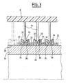
- the rotor 24 is guided in rotation to its ends in bearings (not shown). he has a span 28 on which are threaded a series of rings. Some of these rings, such as rings 32 and 34 (see Figure 3), are simple spacers.
- other rings 37 have an L-shaped section in which conductive rings 33 are housed. Between the rings 34 and 37 made of an electrically insulation is provided a clearance 36.
- a conductive ring 33 made for example of an alloy of copper, gold or gilded brass, is mounted on each ring 37.
- the rings 33 have a semi-circular or other groove 35 form that receives an eyelash 14.
- the ends 20 of the eyelashes have a curved portion 38 to facilitate their insertion into the grooves 35.
- the eyelashes 14 are preloaded: this means that their free end 20 is applied on the slopes with a certain amount of support, called preload, so as to ensure good contact between eyelashes and the track on which they are applied.
- the pre-charge is adjustable.
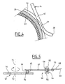
- FIG. 4 shows an enlarged view of the end of an eyelash 14 in contact with a ring 33 of 24.
- the surface of the wires which constitute the eyelashes 14 is covered with one or several layers of enamel 42 with the exception of an area 43 in frictional contact with the ring 33.
- the eyelashes are glazed prior to their use in the collector. This avoids the pollution of the manifold. In addition, this allows their control before use.
- the enameling operation can be performed according to a known method, in particular by soaking the eyelashes in a solution of an electrically insulating material and then by baking in an enameling furnace, such as for example described in EP-0 875 299.
- the common thread enamelling scrolls continuously along an enameling line.
- the enameling line generally comprises an applicator for depositing on the wire an oligomer solution or prepolymers, constituting the insulating material, in a solvent. Additives are usually added in the solution (catalyst, adhesion promoter, etc ).
- This applicator is followed by an enameling furnace comprising a solvent evaporation zone (150 ° C-350 ° C) and a zone of polymerization and crosslinking of the insulating material electrically (350 ° C-550 ° C).
- an enameling furnace comprising a solvent evaporation zone (150 ° C-350 ° C) and a zone of polymerization and crosslinking of the insulating material electrically (350 ° C-550 ° C).
- the wire driver is then cut into sections to form the Eyelashes 14.
- the electrical continuity zone is treated for remove enamel for example by soaking.
- the operation removal of the enamel is preferably carried out after mounting the eyelashes 14 in the supporting structure 2.
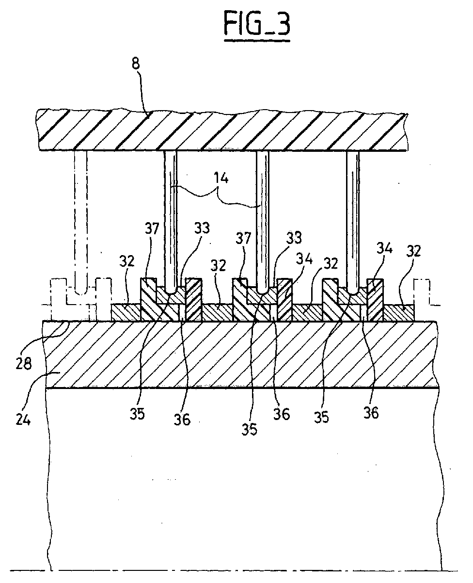
- FIG. 5 shows a second mode of realization of a collector according to the invention.
- the fixed part comprises a support 54, for example in aluminum, consisting of two parts 56 and 58 clamped by a screw 60 and between which is arranged a support of broom 62 which constitutes an electrically conductive element within the meaning of the invention.
- the broom support 62 is constituted by a flexible section electrically conductive blade flattened rectangular made, for example, of copper or a copper alloy. At her free end, she wears a or several brushes 64 of carbon or of another material driver. At the other end, it is connected to a wire electrical conductor 66 that ends with a pod 68 attached to the blade 62, for example by means of a rivet 70. insulation (not shown) is provided between the support 54 and the brush holder 62.
- the moving part 52 is constituted by a disc 72 mobile in rotation about an axis 74.
- the disc 72 comprises circular conductive tracks 76, made by example in silver.
- the broom 64 rubs on the track 76.
- the broom support 62 is pre-loaded in order to apply the broom 64 with a force given on runway 76.
- the flexible blade 62 is electrically isolated by one or more layers of enamel (not shown) These layers of enamel can be likewise chemical nature or of different chemical natures. They are advantageously deposited in several layers successive of a few microns thick. We remove locally the enamel layer in the contact zone 65 between the broom 64 and the flexible blade 62 to ensure the continuity of the electric transmission. We remove also the enamel layer at the contact between the flexible blade 62 and the lug 68 of the electrical conductor 66.
- the enamel used may be of the polyvinyl type, polyurethane, polyester, polyester imide, polyamide imide, polyimide or other.
- the preload adjustment is done after the eyelashes or the broom supports were enamelled, so that the stiffness of the enamel is taken into account when setting the preload.
- the enamel layer 42 Thanks to the presence of the enamel layer 42, it is possible to double insulation of eyelashes or brush holders in the power collector or signals.
- eyelashes or brush holders are isolated by spacing them, but in addition they are isolated by the presence of an enamel layer on each two.
- the preload is not disturbed by the presence of the enamel layer.
- the temperature resistance is better than glue or sheath.
- the invention does not apply not exclusively to rotating manifolds that come to be described but to all types of collectors in which conductive elements transmit signals or electric power by friction between a part fixed and a moving part, for example by friction on a track made on a record or on a turntable.
- the invention also applies to a collector in which the tracks are fixed and the conductive elements are mounted on a rotating part with respect to the tracks.
Landscapes
- Motor Or Generator Current Collectors (AREA)
- Perforating, Stamping-Out Or Severing By Means Other Than Cutting (AREA)
- Cell Electrode Carriers And Collectors (AREA)
- Laminated Bodies (AREA)
- Electrolytic Production Of Metals (AREA)
- Insulating Bodies (AREA)
Abstract
Description
Cependant la présence autour du conducteur d'une gaine isolante d'une certaine épaisseur (habituellement de l'ordre de 100µm), perturbe la force d'application des bras sur la piste conductrice. En outre dans le cas d'une utilisation dans le domaine spatial, le matériau isolant doit conserver une bonne tenue mécanique à température élevée.
Selon une deuxième variante, on monte les éléments électriquement conducteurs sur une structure porteuse du collecteur avant l'étape (c) de traitement de la zone de continuité électrique.
- la figure 1 est une vue en coupe axiale qui illustre la structure générale d'un collecteur tournant,
- la figure 2 est une vue en coupe selon la ligne II-II de la figure 1,
- la figure 3 est une vue en coupe partielle à échelle agrandie des pistes du collecteur des figures 1 et 2,
- la figure 4 est une vue de détail à échelle agrandie de la zone de contact entre un cil conforme à l'invention et une piste du collecteur tournant des figures 1 à 3,
- la figure 5 est une vue schématique en coupe qui illustre la structure générale d'un autre exemple de collecteur tournant.
- ne pas perturber la précharge des cils ou des supports de balais, c'est-à-dire la force d'application des cils ou des supports de balais sur la piste du conducteur.
- être compatible avec les opérations de mise en forme des cils ou des supports de balais sans générer de craquelures de l'émail.
Claims (15)
- Procédé de fabrication d'un élément électriquement conducteur (14, 62) recouverts d'au moins une couche (42) isolante électriquement à l'exception d'une zone (43, 65) de continuité électrique, pour le transfert d'un courant électrique entre deux parties (2, 24, 50, 52) en mouvement l'une par rapport à l'autre, caractérisé en ce qu'il comprend les étapes suivantes :(a) on recouvre ledit élément électriquement conducteur (14, 62) d'une ou de plusieurs couches d'un matériau isolant électriquement,(b) on cuit ledit élément recouvert afin de réticuler ledit matériau pour former une ou plusieurs couches d'émail (42) ,(c) on traite la zone de continuité électrique (43, 65) des éléments électriquement conducteurs (14, 62) afin d'en retirer la ou les couches d'émail.
- Procédé selon la revendication 1, dans lequel lesdits éléments électriquement conducteurs (14, 62) sont montés sur une structure porteuse (2, 50) du collecteur après l'étape (c) de traitement de la zone de continuité électrique.
- Procédé selon la revendication 1, dans lequel lesdits éléments électriquement conducteurs (14, 62) sont montés sur une structure porteuse (2, 50) du collecteur avant l'étape (c) de traitement de la zone de continuité électrique.
- Procédé selon l'une des revendications 1 à 3, dans lequel les éléments électriquement conducteurs sont des cils (14), la zone de continuité électrique étant constituée par une zone de frottement (43) sur une piste conductrice (33, 35) qui se déplace par rapport à lui.
- Procédé selon l'une des revendications 1 à 3, dans lequel les éléments électriquement conducteurs sont des support (62) de balais, la zone de continuité électrique étant constituée par une zone (65) de montage des balais (64) sur le support de balais.
- Procédé selon l'une des revendications 1 à 5, dans lequel l'on retire la ou les couches d'émail.de l'élément électriquement conducteur (42, 62) par attaque chimique, thermique ou mécanique.
- Procédé selon l'une des revendications 1 à 6, dans lequel la ou les couches d'émail (42) choisi dans le groupe comprenant les polyvinyles, les polyuréthanes, les polyesters, les polyester imides, les polyamide imides, les polyimides.
- Procédé selon l'une des revendications 1 à 7, dans lequel l'élément électriquement conducteur comporte plusieurs couches d'émail (42) de nature chimique identique.
- Procédé selon l'une des revendications 1 à 7, dans lequel l'élément électriquement conducteur comporte plusieurs couches d'émail (42) de natures chimiques différentes.
- Elément électriquement conducteur pour le transfert d'un courant électrique entre deux parties (2, 24, 50, 52) en mouvement l'une par rapport à l'autre, réalisé par le procédé selon l'une des revendications 1 à 9, recouvert d'au moins une couche d'émail (42) isolant électriquement à l'exception d'une zone (43, 65) de continuité électrique.
- Elément selon la revendication 10, dans lequel ladite zone de continuité électrique est une zone de frottement en contact avec une piste conductrice qui se déplace par rapport audit élément.
- Elément selon la revendication 10, dans lequel ladite zone de continuité électrique est une zone de montage de balais sur le support de balais, lesdits balais étant en contact avec une piste conductrice qui se déplace par rapport audit élément.
- Collecteur comprenant une première partie (2, 50) et une seconde partie (24, 52) en mouvement l'une par rapport à l'autre, l'une de ces parties supportant une pluralité d'éléments électriquement conducteurs (14, 62) réalisés par le procédé selon l'une des revendications 1 à 9.
- Collecteur selon la revendication 13, comprenant une structure porteuse fixe (2) et un rotor (24) comportant des pistes conductrices cylindriques ou planes et monté tournant dans la structure porteuse, la structure porteuse (2) supportant une pluralité des cils (14) électriquement conducteurs ayant chacun une zone de contact appliquée sur une piste (33) du rotor (24).
- Collecteur selon la revendication 13, comprenant une structure porteuse fixe (50) et un rotor (52) comportant des pistes conductrices (76) cylindriques ou planes et monté tournant dans la structure porteuse, la structure porteuse (50) supportant une pluralité de supports de balais (62) électriquement conducteurs ayant chacun une zone de montage (65) des balais (64) en contact sur une piste (76) du rotor (52).
Applications Claiming Priority (2)
| Application Number | Priority Date | Filing Date | Title |
|---|---|---|---|
| FR0307942 | 2003-07-01 | ||
| FR0307942A FR2857169B1 (fr) | 2003-07-01 | 2003-07-01 | Procede de fabrication d'elements electriquement conducteurs isoles de collecteur tournant et collecteur tournant comportant ces elements electriquement conducteurs |
Publications (2)
| Publication Number | Publication Date |
|---|---|
| EP1494323A1 true EP1494323A1 (fr) | 2005-01-05 |
| EP1494323B1 EP1494323B1 (fr) | 2009-09-23 |
Family
ID=33427650
Family Applications (1)
| Application Number | Title | Priority Date | Filing Date |
|---|---|---|---|
| EP04291564A Expired - Lifetime EP1494323B1 (fr) | 2003-07-01 | 2004-06-21 | Procédé de fabrication d'éléments electriquement conducteurs isolés de collecteur tournant et collecteur tournant comportant ces éléments electriquement conducteurs |
Country Status (5)
| Country | Link |
|---|---|
| US (1) | US7774935B2 (fr) |
| EP (1) | EP1494323B1 (fr) |
| AT (1) | ATE443934T1 (fr) |
| DE (1) | DE602004023255D1 (fr) |
| FR (1) | FR2857169B1 (fr) |
Families Citing this family (12)
| Publication number | Priority date | Publication date | Assignee | Title |
|---|---|---|---|---|
| FR2914277B1 (fr) * | 2007-03-27 | 2009-09-18 | Alcatel Lucent Sas | Dispositif unique de deploiement et reploiement d'appendices spatiaux. |
| US7750493B2 (en) * | 2007-08-14 | 2010-07-06 | General Electric Company | Wind turbine assemblies and slip ring assemblies for wind blade pitch control motors |
| DE102011006820A1 (de) * | 2011-04-06 | 2012-10-11 | Schleifring Und Apparatebau Gmbh | Vibrationsfeste Schleifringanordnung |
| FR2980921B1 (fr) | 2011-10-03 | 2013-10-11 | Centre Nat Etd Spatiales | Collecteur electrique a gaines tubulaires d'isolation mecaniquement independantes des cils. |
| DE102012204830A1 (de) * | 2012-03-26 | 2013-09-26 | Schleifring Und Apparatebau Gmbh | Bürstenblock für eine Schleifringanordnung |
| EP2696450B1 (fr) * | 2012-08-06 | 2020-09-30 | Schleifring GmbH | Balais à faible coût avec un fil couvert d'or |
| DE102012217962A1 (de) * | 2012-10-01 | 2013-09-19 | Siemens Aktiengesellschaft | Bürsteneinheit und Anordnung mit einer Bürsteneinheit zur Stromübertragung an einer Gleitfläche |
| EP2765660A1 (fr) * | 2013-02-07 | 2014-08-13 | ABB Technology AG | Ensemble de bagues collectrices |
| US9214777B2 (en) * | 2014-03-24 | 2015-12-15 | Goodrich Corporation | Landing gear electrical swivel |
| US11449290B2 (en) | 2017-07-14 | 2022-09-20 | Georgia-Pacific Corrugated Llc | Control plan for paper, sheet, and box manufacturing systems |
| US11485101B2 (en) | 2017-07-14 | 2022-11-01 | Georgia-Pacific Corrugated Llc | Controls for paper, sheet, and box manufacturing systems |
| US20190016551A1 (en) | 2017-07-14 | 2019-01-17 | Georgia-Pacific Corrugated, LLC | Reel editor for pre-print paper, sheet, and box manufacturing systems |
Citations (4)
| Publication number | Priority date | Publication date | Assignee | Title |
|---|---|---|---|---|
| US2681564A (en) * | 1953-04-23 | 1954-06-22 | Jr James R Jeromson | Painted slip ring structure and method of making same |
| DE1613183A1 (de) * | 1967-08-25 | 1971-09-23 | Helmut Kever | Federnder Kontaktarm,Buerstenhalter,Stromabnehmer od.dgl. |
| FR2191330A1 (fr) * | 1972-07-05 | 1974-02-01 | Sfim | |
| WO1995018474A1 (fr) * | 1993-12-30 | 1995-07-06 | Ab Volvo | Couverture de surface pour un coupleur electrique et procede d'application de cette couverture de surface |
Family Cites Families (9)
| Publication number | Priority date | Publication date | Assignee | Title |
|---|---|---|---|---|
| US2835866A (en) * | 1954-06-10 | 1958-05-20 | Ward Leonard Electric Co | Variable transformer |
| US2860215A (en) * | 1955-04-15 | 1958-11-11 | B & H Instr Company Inc | Adjustable resistance device |
| US2927230A (en) * | 1957-09-30 | 1960-03-01 | Gen Electric | Carbon brush |
| GB944657A (en) * | 1960-02-02 | 1963-12-18 | Sealectro Corp | Improvements in electrical jack plugs |
| GB969265A (en) * | 1962-03-15 | 1964-09-09 | Sealectro Corp | Improvements in electrical jack plugs |
| JPH0556609A (ja) | 1991-08-08 | 1993-03-05 | Hitachi Ltd | 回転機口出線の自動接続装置 |
| JPH06124615A (ja) | 1992-08-31 | 1994-05-06 | Furukawa Electric Co Ltd:The | エナメル線屑の処理方法 |
| FR2762860B1 (fr) | 1997-05-02 | 1999-07-23 | Alsthom Cge Alcatel | Ligne d'emaillage d'un fil conducteur |
| JP4325280B2 (ja) | 2003-06-02 | 2009-09-02 | パナソニック株式会社 | 電子部品の処理方法 |
-
2003
- 2003-07-01 FR FR0307942A patent/FR2857169B1/fr not_active Expired - Fee Related
-
2004
- 2004-06-21 DE DE602004023255T patent/DE602004023255D1/de not_active Expired - Lifetime
- 2004-06-21 AT AT04291564T patent/ATE443934T1/de not_active IP Right Cessation
- 2004-06-21 EP EP04291564A patent/EP1494323B1/fr not_active Expired - Lifetime
- 2004-06-30 US US10/879,208 patent/US7774935B2/en not_active Expired - Fee Related
Patent Citations (4)
| Publication number | Priority date | Publication date | Assignee | Title |
|---|---|---|---|---|
| US2681564A (en) * | 1953-04-23 | 1954-06-22 | Jr James R Jeromson | Painted slip ring structure and method of making same |
| DE1613183A1 (de) * | 1967-08-25 | 1971-09-23 | Helmut Kever | Federnder Kontaktarm,Buerstenhalter,Stromabnehmer od.dgl. |
| FR2191330A1 (fr) * | 1972-07-05 | 1974-02-01 | Sfim | |
| WO1995018474A1 (fr) * | 1993-12-30 | 1995-07-06 | Ab Volvo | Couverture de surface pour un coupleur electrique et procede d'application de cette couverture de surface |
Also Published As
| Publication number | Publication date |
|---|---|
| DE602004023255D1 (de) | 2009-11-05 |
| EP1494323B1 (fr) | 2009-09-23 |
| FR2857169B1 (fr) | 2006-02-24 |
| US20050000084A1 (en) | 2005-01-06 |
| FR2857169A1 (fr) | 2005-01-07 |
| US7774935B2 (en) | 2010-08-17 |
| ATE443934T1 (de) | 2009-10-15 |
Similar Documents
| Publication | Publication Date | Title |
|---|---|---|
| EP1494323B1 (fr) | Procédé de fabrication d'éléments electriquement conducteurs isolés de collecteur tournant et collecteur tournant comportant ces éléments electriquement conducteurs | |
| EP0662736B1 (fr) | Collecteur électrique tournant à balais multibrins | |
| EP2674190B1 (fr) | Structure d'électrode pour une microsonde multipolaire de détection/stimulation destinée à être implantée dans un vaisseau cardiaque ou cérébral | |
| FR2476896A1 (fr) | Structure de cable electrique | |
| WO2006003282A1 (fr) | Element chauffant, son procede de fabrication, article dote d'un tel element et son procede de fabrication | |
| FR2460053A1 (fr) | Machine electrique a courant fort | |
| FR2485859A1 (fr) | Cable flexible de chauffage electrique a auto-limitation de temperature | |
| CA1137284A (fr) | Procede de fabrication d'un element isolant comportant une portion centrale entouree d'une pluralite d'ailettes, et element isolant obtenu par ce procede | |
| EP1586122B1 (fr) | Module photovoltaique comportant des bornes de connexion avec l'exterieur | |
| CH626193A5 (fr) | ||
| FR3121802A1 (fr) | Machine électrique comportant un manchon conducteur | |
| EP0789423B1 (fr) | Procédé de réalisation d'une connexion électrique par collage d'une cosse rigide sur une piste conductrice, cosse rigide pour la mise en oeuvre du procédé et plaque chauffante comportant la cosse | |
| EP2579399B1 (fr) | Collecteur électrique à gaines tubulaires d'isolation mécaniquement indépendantes des cils | |
| EP0860835A1 (fr) | Fil émaillé de résistance élevée aux décharges partielles | |
| FR2582872A1 (fr) | Plaque porte-balais perfectionnee pour moteur electrique et son procede de fabrication | |
| FR2957729A1 (fr) | Moteur electrique a aimants permanents comportant un stator fractionne | |
| EP3024092A1 (fr) | Assemblage d'un ensemble de raccordement électrique | |
| FR3014388A1 (fr) | Procede de fabrication d'un element chauffant pour balai d'essuie-glace d'un vehicule | |
| EP3178090B1 (fr) | Conducteur électrique pour des applications aéronautiques | |
| EP4580948B1 (fr) | Arrangement de câble électrique comprenant au moins un organe de pincement du câble | |
| EP0855722B1 (fr) | Résistance à forte dissipation de puissance et/ou d'énergie et son procédé de fabrication | |
| EP3109948B1 (fr) | Procede de fabrication de contact electrique, et contact electrique | |
| EP0526287B1 (fr) | Balai de mise au même potentiel électrique d'un rotor et d'un stator d'un enregisteur magnétique | |
| EP0001521B1 (fr) | Perfectionnements aux dispositifs de contact électrique glissant | |
| FR2645332A1 (fr) | Element conducteur composite souple apte a supporter des efforts de flexion et/ou de torsion et gyroscope en faisant application |
Legal Events
| Date | Code | Title | Description |
|---|---|---|---|
| PUAI | Public reference made under article 153(3) epc to a published international application that has entered the european phase |
Free format text: ORIGINAL CODE: 0009012 |
|
| AK | Designated contracting states |
Kind code of ref document: A1 Designated state(s): AT BE BG CH CY CZ DE DK EE ES FI FR GB GR HU IE IT LI LU MC NL PL PT RO SE SI SK TR |
|
| AX | Request for extension of the european patent |
Extension state: AL HR LT LV MK |
|
| 17P | Request for examination filed |
Effective date: 20041216 |
|
| AKX | Designation fees paid |
Designated state(s): AT BE BG CH CY CZ DE DK EE ES FI FR GB GR HU IE IT LI LU MC NL PL PT RO SE SI SK TR |
|
| RAP1 | Party data changed (applicant data changed or rights of an application transferred) |
Owner name: ALCATEL LUCENT |
|
| GRAP | Despatch of communication of intention to grant a patent |
Free format text: ORIGINAL CODE: EPIDOSNIGR1 |
|
| GRAS | Grant fee paid |
Free format text: ORIGINAL CODE: EPIDOSNIGR3 |
|
| GRAA | (expected) grant |
Free format text: ORIGINAL CODE: 0009210 |
|
| RAP1 | Party data changed (applicant data changed or rights of an application transferred) |
Owner name: THALES |
|
| AK | Designated contracting states |
Kind code of ref document: B1 Designated state(s): AT BE BG CH CY CZ DE DK EE ES FI FR GB GR HU IE IT LI LU MC NL PL PT RO SE SI SK TR |
|
| REG | Reference to a national code |
Ref country code: GB Ref legal event code: FG4D Free format text: NOT ENGLISH |
|
| REG | Reference to a national code |
Ref country code: CH Ref legal event code: EP |
|
| REG | Reference to a national code |
Ref country code: IE Ref legal event code: FG4D |
|
| REF | Corresponds to: |
Ref document number: 602004023255 Country of ref document: DE Date of ref document: 20091105 Kind code of ref document: P |
|
| PG25 | Lapsed in a contracting state [announced via postgrant information from national office to epo] |
Ref country code: SE Free format text: LAPSE BECAUSE OF FAILURE TO SUBMIT A TRANSLATION OF THE DESCRIPTION OR TO PAY THE FEE WITHIN THE PRESCRIBED TIME-LIMIT Effective date: 20090923 Ref country code: FI Free format text: LAPSE BECAUSE OF FAILURE TO SUBMIT A TRANSLATION OF THE DESCRIPTION OR TO PAY THE FEE WITHIN THE PRESCRIBED TIME-LIMIT Effective date: 20090923 |
|
| PG25 | Lapsed in a contracting state [announced via postgrant information from national office to epo] |
Ref country code: PL Free format text: LAPSE BECAUSE OF FAILURE TO SUBMIT A TRANSLATION OF THE DESCRIPTION OR TO PAY THE FEE WITHIN THE PRESCRIBED TIME-LIMIT Effective date: 20090923 Ref country code: SI Free format text: LAPSE BECAUSE OF FAILURE TO SUBMIT A TRANSLATION OF THE DESCRIPTION OR TO PAY THE FEE WITHIN THE PRESCRIBED TIME-LIMIT Effective date: 20090923 |
|
| NLV1 | Nl: lapsed or annulled due to failure to fulfill the requirements of art. 29p and 29m of the patents act | ||
| PG25 | Lapsed in a contracting state [announced via postgrant information from national office to epo] |
Ref country code: CY Free format text: LAPSE BECAUSE OF FAILURE TO SUBMIT A TRANSLATION OF THE DESCRIPTION OR TO PAY THE FEE WITHIN THE PRESCRIBED TIME-LIMIT Effective date: 20090923 |
|
| REG | Reference to a national code |
Ref country code: IE Ref legal event code: FD4D |
|
| PG25 | Lapsed in a contracting state [announced via postgrant information from national office to epo] |
Ref country code: ES Free format text: LAPSE BECAUSE OF FAILURE TO SUBMIT A TRANSLATION OF THE DESCRIPTION OR TO PAY THE FEE WITHIN THE PRESCRIBED TIME-LIMIT Effective date: 20100103 Ref country code: RO Free format text: LAPSE BECAUSE OF FAILURE TO SUBMIT A TRANSLATION OF THE DESCRIPTION OR TO PAY THE FEE WITHIN THE PRESCRIBED TIME-LIMIT Effective date: 20090923 Ref country code: EE Free format text: LAPSE BECAUSE OF FAILURE TO SUBMIT A TRANSLATION OF THE DESCRIPTION OR TO PAY THE FEE WITHIN THE PRESCRIBED TIME-LIMIT Effective date: 20090923 Ref country code: CZ Free format text: LAPSE BECAUSE OF FAILURE TO SUBMIT A TRANSLATION OF THE DESCRIPTION OR TO PAY THE FEE WITHIN THE PRESCRIBED TIME-LIMIT Effective date: 20090923 Ref country code: IE Free format text: LAPSE BECAUSE OF FAILURE TO SUBMIT A TRANSLATION OF THE DESCRIPTION OR TO PAY THE FEE WITHIN THE PRESCRIBED TIME-LIMIT Effective date: 20090923 Ref country code: PT Free format text: LAPSE BECAUSE OF FAILURE TO SUBMIT A TRANSLATION OF THE DESCRIPTION OR TO PAY THE FEE WITHIN THE PRESCRIBED TIME-LIMIT Effective date: 20100125 |
|
| PG25 | Lapsed in a contracting state [announced via postgrant information from national office to epo] |
Ref country code: SK Free format text: LAPSE BECAUSE OF FAILURE TO SUBMIT A TRANSLATION OF THE DESCRIPTION OR TO PAY THE FEE WITHIN THE PRESCRIBED TIME-LIMIT Effective date: 20090923 |
|
| PG25 | Lapsed in a contracting state [announced via postgrant information from national office to epo] |
Ref country code: AT Free format text: LAPSE BECAUSE OF FAILURE TO SUBMIT A TRANSLATION OF THE DESCRIPTION OR TO PAY THE FEE WITHIN THE PRESCRIBED TIME-LIMIT Effective date: 20090923 |
|
| PG25 | Lapsed in a contracting state [announced via postgrant information from national office to epo] |
Ref country code: NL Free format text: LAPSE BECAUSE OF FAILURE TO SUBMIT A TRANSLATION OF THE DESCRIPTION OR TO PAY THE FEE WITHIN THE PRESCRIBED TIME-LIMIT Effective date: 20090923 Ref country code: DK Free format text: LAPSE BECAUSE OF FAILURE TO SUBMIT A TRANSLATION OF THE DESCRIPTION OR TO PAY THE FEE WITHIN THE PRESCRIBED TIME-LIMIT Effective date: 20090923 |
|
| PLBE | No opposition filed within time limit |
Free format text: ORIGINAL CODE: 0009261 |
|
| STAA | Information on the status of an ep patent application or granted ep patent |
Free format text: STATUS: NO OPPOSITION FILED WITHIN TIME LIMIT |
|
| 26N | No opposition filed |
Effective date: 20100624 |
|
| PG25 | Lapsed in a contracting state [announced via postgrant information from national office to epo] |
Ref country code: GR Free format text: LAPSE BECAUSE OF FAILURE TO SUBMIT A TRANSLATION OF THE DESCRIPTION OR TO PAY THE FEE WITHIN THE PRESCRIBED TIME-LIMIT Effective date: 20091224 |
|
| BERE | Be: lapsed |
Owner name: THALES Effective date: 20100630 |
|
| PG25 | Lapsed in a contracting state [announced via postgrant information from national office to epo] |
Ref country code: MC Free format text: LAPSE BECAUSE OF NON-PAYMENT OF DUE FEES Effective date: 20100630 |
|
| PG25 | Lapsed in a contracting state [announced via postgrant information from national office to epo] |
Ref country code: IT Free format text: LAPSE BECAUSE OF FAILURE TO SUBMIT A TRANSLATION OF THE DESCRIPTION OR TO PAY THE FEE WITHIN THE PRESCRIBED TIME-LIMIT Effective date: 20090923 |
|
| PG25 | Lapsed in a contracting state [announced via postgrant information from national office to epo] |
Ref country code: BE Free format text: LAPSE BECAUSE OF NON-PAYMENT OF DUE FEES Effective date: 20100630 |
|
| PG25 | Lapsed in a contracting state [announced via postgrant information from national office to epo] |
Ref country code: HU Free format text: LAPSE BECAUSE OF FAILURE TO SUBMIT A TRANSLATION OF THE DESCRIPTION OR TO PAY THE FEE WITHIN THE PRESCRIBED TIME-LIMIT Effective date: 20100324 Ref country code: BG Free format text: LAPSE BECAUSE OF FAILURE TO SUBMIT A TRANSLATION OF THE DESCRIPTION OR TO PAY THE FEE WITHIN THE PRESCRIBED TIME-LIMIT Effective date: 20090923 Ref country code: LU Free format text: LAPSE BECAUSE OF NON-PAYMENT OF DUE FEES Effective date: 20100621 |
|
| PG25 | Lapsed in a contracting state [announced via postgrant information from national office to epo] |
Ref country code: TR Free format text: LAPSE BECAUSE OF FAILURE TO SUBMIT A TRANSLATION OF THE DESCRIPTION OR TO PAY THE FEE WITHIN THE PRESCRIBED TIME-LIMIT Effective date: 20090923 |
|
| REG | Reference to a national code |
Ref country code: FR Ref legal event code: PLFP Year of fee payment: 13 |
|
| REG | Reference to a national code |
Ref country code: FR Ref legal event code: PLFP Year of fee payment: 14 |
|
| REG | Reference to a national code |
Ref country code: FR Ref legal event code: PLFP Year of fee payment: 15 |
|
| PGFP | Annual fee paid to national office [announced via postgrant information from national office to epo] |
Ref country code: CH Payment date: 20180614 Year of fee payment: 15 Ref country code: DE Payment date: 20180605 Year of fee payment: 15 |
|
| PGFP | Annual fee paid to national office [announced via postgrant information from national office to epo] |
Ref country code: FR Payment date: 20180529 Year of fee payment: 15 |
|
| PGFP | Annual fee paid to national office [announced via postgrant information from national office to epo] |
Ref country code: GB Payment date: 20180611 Year of fee payment: 15 |
|
| REG | Reference to a national code |
Ref country code: DE Ref legal event code: R119 Ref document number: 602004023255 Country of ref document: DE |
|
| REG | Reference to a national code |
Ref country code: CH Ref legal event code: PL |
|
| GBPC | Gb: european patent ceased through non-payment of renewal fee |
Effective date: 20190621 |
|
| PG25 | Lapsed in a contracting state [announced via postgrant information from national office to epo] |
Ref country code: DE Free format text: LAPSE BECAUSE OF NON-PAYMENT OF DUE FEES Effective date: 20200101 Ref country code: GB Free format text: LAPSE BECAUSE OF NON-PAYMENT OF DUE FEES Effective date: 20190621 |
|
| PG25 | Lapsed in a contracting state [announced via postgrant information from national office to epo] |
Ref country code: LI Free format text: LAPSE BECAUSE OF NON-PAYMENT OF DUE FEES Effective date: 20190630 Ref country code: CH Free format text: LAPSE BECAUSE OF NON-PAYMENT OF DUE FEES Effective date: 20190630 |
|
| PG25 | Lapsed in a contracting state [announced via postgrant information from national office to epo] |
Ref country code: FR Free format text: LAPSE BECAUSE OF NON-PAYMENT OF DUE FEES Effective date: 20190630 |