EP1494323B1 - Verfahren zur Herstellung isolierter elektrisch leitender Teile eines sich drehenden Kollektors und ein sich drehender Kollektor mit den elektrisch leitenden Teilen - Google Patents
Verfahren zur Herstellung isolierter elektrisch leitender Teile eines sich drehenden Kollektors und ein sich drehender Kollektor mit den elektrisch leitenden Teilen Download PDFInfo
- Publication number
- EP1494323B1 EP1494323B1 EP04291564A EP04291564A EP1494323B1 EP 1494323 B1 EP1494323 B1 EP 1494323B1 EP 04291564 A EP04291564 A EP 04291564A EP 04291564 A EP04291564 A EP 04291564A EP 1494323 B1 EP1494323 B1 EP 1494323B1
- Authority
- EP
- European Patent Office
- Prior art keywords
- electrically conductive
- zone
- enamel
- carrier structure
- collector
- Prior art date
- Legal status (The legal status is an assumption and is not a legal conclusion. Google has not performed a legal analysis and makes no representation as to the accuracy of the status listed.)
- Expired - Lifetime
Links
Images

Classifications
-
- H—ELECTRICITY
- H01—ELECTRIC ELEMENTS
- H01R—ELECTRICALLY-CONDUCTIVE CONNECTIONS; STRUCTURAL ASSOCIATIONS OF A PLURALITY OF MUTUALLY-INSULATED ELECTRICAL CONNECTING ELEMENTS; COUPLING DEVICES; CURRENT COLLECTORS
- H01R39/00—Rotary current collectors, distributors or interrupters
- H01R39/02—Details for dynamo electric machines
- H01R39/38—Brush holders
- H01R39/39—Brush holders wherein the brush is fixedly mounted in the holder
-
- H—ELECTRICITY
- H01—ELECTRIC ELEMENTS
- H01R—ELECTRICALLY-CONDUCTIVE CONNECTIONS; STRUCTURAL ASSOCIATIONS OF A PLURALITY OF MUTUALLY-INSULATED ELECTRICAL CONNECTING ELEMENTS; COUPLING DEVICES; CURRENT COLLECTORS
- H01R4/00—Electrically-conductive connections between two or more conductive members in direct contact, i.e. touching one another; Means for effecting or maintaining such contact; Electrically-conductive connections having two or more spaced connecting locations for conductors and using contact members penetrating insulation
- H01R4/70—Insulation of connections
-
- Y—GENERAL TAGGING OF NEW TECHNOLOGICAL DEVELOPMENTS; GENERAL TAGGING OF CROSS-SECTIONAL TECHNOLOGIES SPANNING OVER SEVERAL SECTIONS OF THE IPC; TECHNICAL SUBJECTS COVERED BY FORMER USPC CROSS-REFERENCE ART COLLECTIONS [XRACs] AND DIGESTS
- Y10—TECHNICAL SUBJECTS COVERED BY FORMER USPC
- Y10T—TECHNICAL SUBJECTS COVERED BY FORMER US CLASSIFICATION
- Y10T29/00—Metal working
- Y10T29/49—Method of mechanical manufacture
- Y10T29/49002—Electrical device making
- Y10T29/49009—Dynamoelectric machine
-
- Y—GENERAL TAGGING OF NEW TECHNOLOGICAL DEVELOPMENTS; GENERAL TAGGING OF CROSS-SECTIONAL TECHNOLOGIES SPANNING OVER SEVERAL SECTIONS OF THE IPC; TECHNICAL SUBJECTS COVERED BY FORMER USPC CROSS-REFERENCE ART COLLECTIONS [XRACs] AND DIGESTS
- Y10—TECHNICAL SUBJECTS COVERED BY FORMER USPC
- Y10T—TECHNICAL SUBJECTS COVERED BY FORMER US CLASSIFICATION
- Y10T29/00—Metal working
- Y10T29/49—Method of mechanical manufacture
- Y10T29/49002—Electrical device making
- Y10T29/49117—Conductor or circuit manufacturing
- Y10T29/49169—Assembling electrical component directly to terminal or elongated conductor
-
- Y—GENERAL TAGGING OF NEW TECHNOLOGICAL DEVELOPMENTS; GENERAL TAGGING OF CROSS-SECTIONAL TECHNOLOGIES SPANNING OVER SEVERAL SECTIONS OF THE IPC; TECHNICAL SUBJECTS COVERED BY FORMER USPC CROSS-REFERENCE ART COLLECTIONS [XRACs] AND DIGESTS
- Y10—TECHNICAL SUBJECTS COVERED BY FORMER USPC
- Y10T—TECHNICAL SUBJECTS COVERED BY FORMER US CLASSIFICATION
- Y10T29/00—Metal working
- Y10T29/49—Method of mechanical manufacture
- Y10T29/49002—Electrical device making
- Y10T29/49117—Conductor or circuit manufacturing
- Y10T29/49204—Contact or terminal manufacturing
- Y10T29/49208—Contact or terminal manufacturing by assembling plural parts
- Y10T29/4921—Contact or terminal manufacturing by assembling plural parts with bonding
- Y10T29/49211—Contact or terminal manufacturing by assembling plural parts with bonding of fused material
Definitions
- the invention relates to a method of manufacturing electrically conductive elements isolated from rotating collector and a rotating collector for the spatial domain comprising these electrically conductive elements.
- Rotary manifolds are used to transfer electrical power or signals between moving parts relative to each other. They generally comprise a fixed carrier structure, called a stator, supporting conductive wires called eyelashes, and a rotating part, the rotor, carrying a plurality of cylindrical conductive tracks on which the ends of the eyelashes are in electrical contact.
- the eyelashes on the one hand, the tracks on the other hand, are connected to electrical conductors through which the power or the signals pass.
- the conductive yarns or eyelashes are generally made of copper, gold, platinum, copper alloy, gold alloy or platinum alloy.
- the power or the electrical signals are transferred from the fixed part to the mobile part by brushes which rub with a cylindrical or flat conductive track. These brushes are mounted on flexible brush holders.
- the eyelashes and the brush supports constitute electrically conductive elements within the meaning of the present invention. Since they are drivers, they must be isolated from each other. This isolation is currently performed by spacing the eyelashes or brush holders between them. This solution has the disadvantage of being sensitive to pollution by particles or a conductive plasma which can cause short circuits between eyelashes or adjacent brush holders. In the space domain to which the invention applies, such risks are not permissible in view of the required reliability.
- the document DE-1,613,183 describes elastic arms. At their end is brazed pad in rubbing contact on a conductive track.
- the elastic element is constituted by the conductor itself which is surrounded by an insulating sheath of flexible synthetic material.
- an insulating sheath of flexible synthetic material usually of the order of 100 .mu.m.
- the present invention relates to a method of manufacturing insulated electrically conductive elements, particularly eyelashes and collector brush supports and a rotating collector comprising these eyelashes and / or these brush holders which overcome this disadvantage.
- an electrically conductive element for the transfer of an electric current between two moving parts relative to each other.
- This electrically conductive element is covered with at least one layer of insulating enamel electrically, with the exception of a zone of electrical continuity.
- the electrical continuity zone is a friction zone in contact with a conductive track that moves relative thereto.
- the electrical continuity zone is a mounting zone for the brushes, which are in contact with a conductive track that moves relative to them.
- the electrically conductive elements are mounted on a carrier structure of the collector after the step (c) of treatment of the electrical continuity zone.
- the electrically conductive elements are mounted on a carrier structure of the collector before the step (c) of treatment of the electrical continuity zone.
- the enamel layer is removed by etching, thermal or mechanical etching.
- the enamel layer or layers are chosen from the group comprising polyvinyls, polyurethanes, polyesters, polyester imides, polyamide imides, polyimides.
- the electrically conductive element may comprise several layers of enamel of the same chemical nature or of different natures.
- the invention also relates to a collector comprising a first part and a second part moving relative to each other, one of these parts supporting a plurality of electrically conductive elements made according to the method of the invention.
- the electrically conductive elements are covered with at least one layer of electrically insulating enamel with the exception of a zone of electrical continuity zone.
- the collector comprises a fixed carrier structure and a rotor comprising conductive tracks and rotatably mounted in the carrier structure, the carrier structure supporting a plurality of electrically conductive cilia each having a contact zone applied to a rotor track.
- the collector comprises a fixed carrier structure and a rotor comprising cylindrical or flat conductive tracks and rotatably mounted in the carrier structure, the carrier structure supporting a plurality of electrically conductive brush supports each having a mounting zone of brushes in contact on a rotor track.
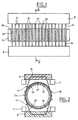
- the collector shown on Figures 1 and 2 comprises a fixed support structure 2 which supports two eyelash supports 8.
- the eyelashes 14 comprise a flat part 15 held in an eyelash holder 8 by a cover or by a resin filling and two free ends 20 arranged on either side
- the eyelashes are made of copper or copper alloy, or other good conducting metals such as gold, silver, platinum or one of their alloys.
- the eyelashes 14 are made of gold alloy and have a circular section. However, it is understood that in the context of the invention, they may have another section, for example square, rectangular or other.
- Each eyelash support 8 is fixed, for example by screws (not shown), on two flats of the supporting structure 2.
- a rotor 24 is rotatably mounted inside the supporting structure 2.
- the rotor 24 is guided in rotation at its ends in bearings (not shown). It comprises a bearing 28 on which are threaded a series of rings. Some of these rings, such as rings 32 and 34 (see figure 3 ), are simple spacers.
- Other rings 37 have an L-shaped section in which conductive rings 33 are housed. Between the rings 34 and 37 made of an electrically insulating material is formed a set 36.
- a conductive ring 33 made for example of a copper alloy, gold or golden brass, is mounted on each ring 37.
- the rings 33 have a semi-circular groove or other shape which receives an eyelash 14.
- the ends 20 of the eyelashes comprise a curved portion 38 intended to facilitate their insertion into the grooves 35.
- the eyelashes 14 are preloaded: this means that their free end 20 is applied to the tracks with a certain support force, called preload , so as to ensure good contact between the eyelashes and the track on which they are applied.
- the pre-charge is adjustable.
- the eyelashes are glazed prior to their use in the collector. This avoids the pollution of the collector. In addition, this allows their control before use.
- the enameling operation can be carried out according to a known method, in particular by soaking the eyelashes in a solution of an electrically insulating material, then by cooking in an enameling furnace, such as that described in the document EP-0 875 299 .
- the enameled conductor runs continuously along an enameling line.
- the enameling line generally comprises an applicator for depositing on the wire a solution of oligomers or prepolymers, constituting the insulating material, in a solvent. Additives are usually added to the solution (catalyst, adhesion promoter, etc.).
- This applicator is followed by an enameling furnace comprising a solvent evaporation zone (150 ° C.-350 ° C.) and a polymerization and crosslinking zone of the electrically insulating material (350 ° C.-550 ° C.).
- an enameling furnace comprising a solvent evaporation zone (150 ° C.-350 ° C.) and a polymerization and crosslinking zone of the electrically insulating material (350 ° C.-550 ° C.).
- the conductive wire is then cut into sections to form the eyelashes 14.
- the electrical continuity zone is treated to remove enamel for example by dipping.
- the enamel removal operation is preferably carried out after mounting the eyelashes 14 in the carrier structure 2.
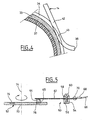
- FIG. 5 a second embodiment of a collector according to the invention. It comprises a fixed part 50 and a mobile part 52.
- the fixed part comprises a support 54, for example made of aluminum, consisting of two parts 56 and 58 clamped by a screw 60 and between which is disposed a brush holder 62 which constitutes a electrically conductive element within the meaning of the invention.
- the brush holder 62 is constituted by an electrically conductive flexible blade of flattened rectangular section made, for example, of copper or a copper alloy. At its free end, it carries one or more brushes 64 of carbon or other conductive material.
- a wire electrical conductor 66 which terminates in a lug 68 fixed to the blade 62, for example by means of a rivet 70.
- An insulation (not shown) is provided between the support 54 and the brush holder 62.
- the movable portion 52 is constituted by a disc 72 movable in rotation about an axis 74.
- the disc 72 comprises circular conductive tracks 76, made for example of silver.
- the broom 64 rubs on the track 76.
- the broom support 62 is pre-loaded to apply the broom 64 with a given force on the track 76.
- the flexible blade 62 is electrically insulated by one or more layers of enamel (not shown). These enamel layers can be of the same chemical nature or of different chemical natures. They are advantageously deposited in several successive layers of a few microns thick.
- the enamel layer is locally removed in the contact zone 65 between the brush 64 and the flexible blade 62 to ensure the continuity of the electrical transmission.
- the enamel layer is also removed at the contact between the flexible blade 62 and the lug 68 of the electrical conductor 66.
- the enamel used may be polyvinyl type, polyurethane, polyester, polyester imide, polyamide imide, polyimide or other.
- the preload adjustment is done after the eyelashes or brush holders have been enamelled, so that the stiffness of the enamel is taken into account when adjusting the preload.
- the eyelashes or brush holders Due to the presence of the enamel layer 42, a double insulation of the eyelashes or brush holders in the power or signal collector is achieved.
- the eyelashes or brush holders are isolated by spacing them, but furthermore they are isolated by the presence of an enamel layer on each of them.
- the preload is not disturbed by the presence of the enamel layer.
- the temperature resistance is better than that of an adhesive or a sheath.
- the invention does not apply exclusively to the rotary manifolds which have just been described, but to all types of collectors in which conductive elements transmit signals or electrical power by friction between a part fixed and a moving part, for example by friction on a track made on a record or on a turntable.
- the invention also applies to a collector in which the tracks are fixed and the conductive elements are mounted on a rotating part relative to the tracks.
Landscapes
- Motor Or Generator Current Collectors (AREA)
- Insulating Bodies (AREA)
- Laminated Bodies (AREA)
- Electrolytic Production Of Metals (AREA)
- Perforating, Stamping-Out Or Severing By Means Other Than Cutting (AREA)
- Cell Electrode Carriers And Collectors (AREA)
Claims (15)
- Verfahren zur Herstellung eines elektrisch leitenden Elements (14, 62), das mit Ausnahme einer Zone (43, 65) elektrischer Kontinuität mit mindestens einer elektrisch isolierenden Schicht (42) bedeckt ist, zur Übertragung eines elektrischen Stroms zwischen zwei zueinander in Bewegung befindlichen Teilen (2, 24, 50, 52), dadurch gekennzeichnet, dass es die folgenden Schritte aufweist:(a)das elektrisch leitende Element (14, 62) wird mit einer oder mehreren Schichten aus einem elektrisch isolierenden Werkstoff bedeckt,(b)das bedeckte Element wird gebrannt, um den Werkstoff zu vernetzen, um eine oder mehrere Lackschichten (42) zu bilden,(c)die Zone elektrischer Kontinuität (43, 65) der elektrisch leitenden Elemente (14, 62) wird behandelt, um die Lackschicht(en) zu entfernen.
- Verfahren nach Anspruch 1, bei dem die elektrisch leitenden Elemente (14, 62) nach dem Schritt (c) der Behandlung der Zone elektrischer Kontinuität auf eine Tragstruktur (2, 50) des Kollektors montiert werden.
- Verfahren nach Anspruch 1, bei dem die elektrisch leitenden Elemente (14, 62) vor dem Schritt (c) der Behandlung der Zone elektrischer Kontinuität auf eine Tragstruktur (2, 50) des Kollektors montiert werden.
- Verfahren nach einem der Ansprüche 1 bis 3, bei dem die elektrisch leitenden Elemente Wimpern (14) sind, wobei die Zone elektrischer Kontinuität aus einer Reibungszone (43) auf einer Leiterbahn (33, 35) besteht, die sich in Bezug auf sie verschiebt.
- Verfahren nach einem der Ansprüche 1 bis 3, bei dem die elektrisch leitenden Elemente Bürstenhalter (62) sind, wobei die Zone elektrischer Kontinuität aus einer Zone (65) der Montage der Bürsten (64) auf den Bürstenhalter besteht.
- Verfahren nach einem der Ansprüche 1 bis 5, bei dem die Lackschicht(en) von dem elektrisch leitenden Element (42, 62) durch chemischen, thermischen oder mechanischen Angriff entfernt wird (werden).
- Verfahren nach einem der Ansprüche 1 bis 6, bei dem die Lackschichten (42) aus der Gruppe ausgewählt werden, die die Polyvinyle, die Polyurethane, die Polyester, die Polyesterimide, die Polyamidimide, die Polyimide enthält.
- Verfahren nach einem der Ansprüche 1 bis 7, bei dem das elektrisch leitende Element mehrere Lackschichten (42) gleicher chemischer Beschaffenheit aufweist.
- Verfahren nach einem der Ansprüche 1 bis 7, bei dem das elektrisch leitende Element mehrere Lackschichten (42) mit unterschiedlichen chemischen Beschaffenheiten aufweist.
- Elektrisch leitendes Element zur Übertragung eines elektrischen Stroms zwischen zwei zueinander in Bewegung befindlichen Teilen (2, 24, 50, 52), hergestellt durch das Verfahren nach einem der Ansprüche 1 bis 9, das mit Ausnahme einer Zone (43, 65) elektrischer Kontinuität mit mindestens einer Schicht eines elektrisch isolierenden Lacks (42) bedeckt ist.
- Element nach Anspruch 10, bei dem die Zone elektrischer Kontinuität eine Reibungszone in Kontakt mit einer Leiterbahn ist, die sich bezüglich des Elements verschiebt.
- Element nach Anspruch 10, bei dem die Zone elektrischer Kontinuität eine Zone der Montage von Bürsten auf den Bürstenhalter ist, wobei die Bürsten mit einer Leiterbahn in Kontakt sind, die sich bezüglich des Elements verschiebt.
- Kollektor, der einen ersten Teil (2, 50) und einen zweiten Teil (24, 52) aufweist, die zueinander in Bewegung sind, wobei einer dieser Teile mehrere elektrisch leitende Elemente (14, 62) trägt, die durch das Verfahren nach einem der Ansprüche 1 bis 9 hergestellt werden.
- Kollektor nach Anspruch 13, der eine feste Tragstruktur (2) und einen Rotor (24) enthält, der zylindrische oder ebene Leiterbahnen aufweist und in der Tragstruktur drehend montiert ist, wobei die Tragstruktur (2) mehrere elektrisch leitende Wimpern (14) trägt, die je eine auf eine Bahn (33) des Rotors (24) aufgelegte Kontaktzone haben.
- Kollektor nach Anspruch 13, der eine feste Tragstruktur (50) und einen Rotor (52) enthält, der zylindrische oder ebene Leiterbahnen (76) aufweist und in der Tragstruktur drehend montiert ist, wobei die Tragstruktur (50) mehrere elektrisch leitende Bürstenhalter (62) trägt, die je eine Montagezone (65) der Bürsten (64) in Kontakt auf einer Bahn (76) des Rotors (52) haben.
Applications Claiming Priority (2)
| Application Number | Priority Date | Filing Date | Title |
|---|---|---|---|
| FR0307942 | 2003-07-01 | ||
| FR0307942A FR2857169B1 (fr) | 2003-07-01 | 2003-07-01 | Procede de fabrication d'elements electriquement conducteurs isoles de collecteur tournant et collecteur tournant comportant ces elements electriquement conducteurs |
Publications (2)
| Publication Number | Publication Date |
|---|---|
| EP1494323A1 EP1494323A1 (de) | 2005-01-05 |
| EP1494323B1 true EP1494323B1 (de) | 2009-09-23 |
Family
ID=33427650
Family Applications (1)
| Application Number | Title | Priority Date | Filing Date |
|---|---|---|---|
| EP04291564A Expired - Lifetime EP1494323B1 (de) | 2003-07-01 | 2004-06-21 | Verfahren zur Herstellung isolierter elektrisch leitender Teile eines sich drehenden Kollektors und ein sich drehender Kollektor mit den elektrisch leitenden Teilen |
Country Status (5)
| Country | Link |
|---|---|
| US (1) | US7774935B2 (de) |
| EP (1) | EP1494323B1 (de) |
| AT (1) | ATE443934T1 (de) |
| DE (1) | DE602004023255D1 (de) |
| FR (1) | FR2857169B1 (de) |
Families Citing this family (12)
| Publication number | Priority date | Publication date | Assignee | Title |
|---|---|---|---|---|
| FR2914277B1 (fr) * | 2007-03-27 | 2009-09-18 | Alcatel Lucent Sas | Dispositif unique de deploiement et reploiement d'appendices spatiaux. |
| US7750493B2 (en) * | 2007-08-14 | 2010-07-06 | General Electric Company | Wind turbine assemblies and slip ring assemblies for wind blade pitch control motors |
| DE102011006820A1 (de) * | 2011-04-06 | 2012-10-11 | Schleifring Und Apparatebau Gmbh | Vibrationsfeste Schleifringanordnung |
| FR2980921B1 (fr) | 2011-10-03 | 2013-10-11 | Centre Nat Etd Spatiales | Collecteur electrique a gaines tubulaires d'isolation mecaniquement independantes des cils. |
| DE102012204830A1 (de) * | 2012-03-26 | 2013-09-26 | Schleifring Und Apparatebau Gmbh | Bürstenblock für eine Schleifringanordnung |
| EP2696450B1 (de) * | 2012-08-06 | 2020-09-30 | Schleifring GmbH | Günstig herstellbare Bürste mit goldbeschichtetem Draht |
| DE102012217962A1 (de) * | 2012-10-01 | 2013-09-19 | Siemens Aktiengesellschaft | Bürsteneinheit und Anordnung mit einer Bürsteneinheit zur Stromübertragung an einer Gleitfläche |
| EP2765660A1 (de) * | 2013-02-07 | 2014-08-13 | ABB Technology AG | Schleifringanordnung |
| US9214777B2 (en) * | 2014-03-24 | 2015-12-15 | Goodrich Corporation | Landing gear electrical swivel |
| US20190016551A1 (en) | 2017-07-14 | 2019-01-17 | Georgia-Pacific Corrugated, LLC | Reel editor for pre-print paper, sheet, and box manufacturing systems |
| US11449290B2 (en) | 2017-07-14 | 2022-09-20 | Georgia-Pacific Corrugated Llc | Control plan for paper, sheet, and box manufacturing systems |
| US11485101B2 (en) | 2017-07-14 | 2022-11-01 | Georgia-Pacific Corrugated Llc | Controls for paper, sheet, and box manufacturing systems |
Family Cites Families (13)
| Publication number | Priority date | Publication date | Assignee | Title |
|---|---|---|---|---|
| US2681564A (en) * | 1953-04-23 | 1954-06-22 | Jr James R Jeromson | Painted slip ring structure and method of making same |
| US2835866A (en) * | 1954-06-10 | 1958-05-20 | Ward Leonard Electric Co | Variable transformer |
| US2860215A (en) * | 1955-04-15 | 1958-11-11 | B & H Instr Company Inc | Adjustable resistance device |
| US2927230A (en) * | 1957-09-30 | 1960-03-01 | Gen Electric | Carbon brush |
| GB944657A (en) * | 1960-02-02 | 1963-12-18 | Sealectro Corp | Improvements in electrical jack plugs |
| GB969265A (en) * | 1962-03-15 | 1964-09-09 | Sealectro Corp | Improvements in electrical jack plugs |
| DE1613183B2 (de) * | 1967-08-25 | 1973-05-30 | Kever, Helmut, 8900 Augsburg | Federnder kontaktarm |
| FR2191330B1 (de) * | 1972-07-05 | 1976-08-06 | Sfim | |
| JPH0556609A (ja) | 1991-08-08 | 1993-03-05 | Hitachi Ltd | 回転機口出線の自動接続装置 |
| JPH06124615A (ja) | 1992-08-31 | 1994-05-06 | Furukawa Electric Co Ltd:The | エナメル線屑の処理方法 |
| SE506354C2 (sv) * | 1993-12-30 | 1997-12-08 | Volvo Ab | Ytskydd för en elektrisk kopplingsenhet och förfarande för applicering av nämnda ytskydd |
| FR2762860B1 (fr) | 1997-05-02 | 1999-07-23 | Alsthom Cge Alcatel | Ligne d'emaillage d'un fil conducteur |
| JP4325280B2 (ja) | 2003-06-02 | 2009-09-02 | パナソニック株式会社 | 電子部品の処理方法 |
-
2003
- 2003-07-01 FR FR0307942A patent/FR2857169B1/fr not_active Expired - Fee Related
-
2004
- 2004-06-21 AT AT04291564T patent/ATE443934T1/de not_active IP Right Cessation
- 2004-06-21 EP EP04291564A patent/EP1494323B1/de not_active Expired - Lifetime
- 2004-06-21 DE DE602004023255T patent/DE602004023255D1/de not_active Expired - Lifetime
- 2004-06-30 US US10/879,208 patent/US7774935B2/en not_active Expired - Fee Related
Also Published As
| Publication number | Publication date |
|---|---|
| US20050000084A1 (en) | 2005-01-06 |
| US7774935B2 (en) | 2010-08-17 |
| FR2857169B1 (fr) | 2006-02-24 |
| ATE443934T1 (de) | 2009-10-15 |
| FR2857169A1 (fr) | 2005-01-07 |
| DE602004023255D1 (de) | 2009-11-05 |
| EP1494323A1 (de) | 2005-01-05 |
Similar Documents
| Publication | Publication Date | Title |
|---|---|---|
| EP1494323B1 (de) | Verfahren zur Herstellung isolierter elektrisch leitender Teile eines sich drehenden Kollektors und ein sich drehender Kollektor mit den elektrisch leitenden Teilen | |
| WO2006003282A1 (fr) | Element chauffant, son procede de fabrication, article dote d'un tel element et son procede de fabrication | |
| FR2476896A1 (fr) | Structure de cable electrique | |
| FR2485859A1 (fr) | Cable flexible de chauffage electrique a auto-limitation de temperature | |
| CA1137284A (fr) | Procede de fabrication d'un element isolant comportant une portion centrale entouree d'une pluralite d'ailettes, et element isolant obtenu par ce procede | |
| EP0662736A1 (de) | Drehender elektrischer Schleifring mit Mehrdrahtbürsten | |
| EP1586122B1 (de) | Photovoltaisches modul mit aussenanschlussklemmen | |
| FR2991882A1 (fr) | Structure d'electrode pour une microsonde multipolaire de detection/stimulation destinee a etre implantee dans un vaisseau cardiaque ou cerebral | |
| CH626193A5 (de) | ||
| EP2783376B1 (de) | Elektrischer schalter mit reibkontakt | |
| EP0789423B1 (de) | Verfahren zur Herstellung einer elektrischen Verbindung durch Kleben eines starren Anschlusselements auf eine Leiterbahn, ein starres Anschlusselement zur Durchführung dieses Verfahrens und eine dieses Anschlusselement tragende Heizplatte | |
| EP2579399B1 (de) | Stromsammelleitung mit Schlauchummantelungen zur mechanischen Isolierung, die unabhängig von den Bürsten sind | |
| FR3014388A1 (fr) | Procede de fabrication d'un element chauffant pour balai d'essuie-glace d'un vehicule | |
| FR2918786A1 (fr) | Fil electrique de transmission de signaux destine a l'industrie aeronautique et spatiale. | |
| EP3821504B1 (de) | System zur leistungsübertragung zwischen einem rotierenden element und einem festen element | |
| EP3178090B1 (de) | Elektrischer leiter für luftfahrtanwendungen | |
| EP0855722B1 (de) | Hoher energie- und/oder leistungsauflösender Widerstand und Herstellungsverfahren | |
| EP0526287B1 (de) | Kohlenbürste, die sich auf demselben elektrischen Potential befindet wie der Rotor und der Stator eines magnetischen Aufnahmeapparates | |
| EP0001521B1 (de) | Massnahmen zur Verbesserung elektrischer Schleifkontaktvorrichtungen | |
| CH683303A5 (fr) | Elément composite conducteur souple apte à supporter des efforts de flexion et de torsion et gyroscope en faisant application. | |
| CH364301A (fr) | Induit de machine électrique tournante à entrefer axial | |
| EP3109948A1 (de) | Herstellungsverfahren eines elektrischen kontakts, und elektrischer kontakt | |
| FR2777383A1 (fr) | Conducteur multicouche a effet de peau reduit | |
| FR2770029A1 (fr) | Plage de test a positionnement automatique de microsonde et procede de realisation d'une telle plage de test | |
| FR2703181A1 (fr) | Conducteur en alliage d'aluminium protégé contre la corrosion et câble coaxial en faisant application. |
Legal Events
| Date | Code | Title | Description |
|---|---|---|---|
| PUAI | Public reference made under article 153(3) epc to a published international application that has entered the european phase |
Free format text: ORIGINAL CODE: 0009012 |
|
| AK | Designated contracting states |
Kind code of ref document: A1 Designated state(s): AT BE BG CH CY CZ DE DK EE ES FI FR GB GR HU IE IT LI LU MC NL PL PT RO SE SI SK TR |
|
| AX | Request for extension of the european patent |
Extension state: AL HR LT LV MK |
|
| 17P | Request for examination filed |
Effective date: 20041216 |
|
| AKX | Designation fees paid |
Designated state(s): AT BE BG CH CY CZ DE DK EE ES FI FR GB GR HU IE IT LI LU MC NL PL PT RO SE SI SK TR |
|
| RAP1 | Party data changed (applicant data changed or rights of an application transferred) |
Owner name: ALCATEL LUCENT |
|
| GRAP | Despatch of communication of intention to grant a patent |
Free format text: ORIGINAL CODE: EPIDOSNIGR1 |
|
| GRAS | Grant fee paid |
Free format text: ORIGINAL CODE: EPIDOSNIGR3 |
|
| GRAA | (expected) grant |
Free format text: ORIGINAL CODE: 0009210 |
|
| RAP1 | Party data changed (applicant data changed or rights of an application transferred) |
Owner name: THALES |
|
| AK | Designated contracting states |
Kind code of ref document: B1 Designated state(s): AT BE BG CH CY CZ DE DK EE ES FI FR GB GR HU IE IT LI LU MC NL PL PT RO SE SI SK TR |
|
| REG | Reference to a national code |
Ref country code: GB Ref legal event code: FG4D Free format text: NOT ENGLISH |
|
| REG | Reference to a national code |
Ref country code: CH Ref legal event code: EP |
|
| REG | Reference to a national code |
Ref country code: IE Ref legal event code: FG4D |
|
| REF | Corresponds to: |
Ref document number: 602004023255 Country of ref document: DE Date of ref document: 20091105 Kind code of ref document: P |
|
| PG25 | Lapsed in a contracting state [announced via postgrant information from national office to epo] |
Ref country code: SE Free format text: LAPSE BECAUSE OF FAILURE TO SUBMIT A TRANSLATION OF THE DESCRIPTION OR TO PAY THE FEE WITHIN THE PRESCRIBED TIME-LIMIT Effective date: 20090923 Ref country code: FI Free format text: LAPSE BECAUSE OF FAILURE TO SUBMIT A TRANSLATION OF THE DESCRIPTION OR TO PAY THE FEE WITHIN THE PRESCRIBED TIME-LIMIT Effective date: 20090923 |
|
| PG25 | Lapsed in a contracting state [announced via postgrant information from national office to epo] |
Ref country code: PL Free format text: LAPSE BECAUSE OF FAILURE TO SUBMIT A TRANSLATION OF THE DESCRIPTION OR TO PAY THE FEE WITHIN THE PRESCRIBED TIME-LIMIT Effective date: 20090923 Ref country code: SI Free format text: LAPSE BECAUSE OF FAILURE TO SUBMIT A TRANSLATION OF THE DESCRIPTION OR TO PAY THE FEE WITHIN THE PRESCRIBED TIME-LIMIT Effective date: 20090923 |
|
| NLV1 | Nl: lapsed or annulled due to failure to fulfill the requirements of art. 29p and 29m of the patents act | ||
| PG25 | Lapsed in a contracting state [announced via postgrant information from national office to epo] |
Ref country code: CY Free format text: LAPSE BECAUSE OF FAILURE TO SUBMIT A TRANSLATION OF THE DESCRIPTION OR TO PAY THE FEE WITHIN THE PRESCRIBED TIME-LIMIT Effective date: 20090923 |
|
| REG | Reference to a national code |
Ref country code: IE Ref legal event code: FD4D |
|
| PG25 | Lapsed in a contracting state [announced via postgrant information from national office to epo] |
Ref country code: ES Free format text: LAPSE BECAUSE OF FAILURE TO SUBMIT A TRANSLATION OF THE DESCRIPTION OR TO PAY THE FEE WITHIN THE PRESCRIBED TIME-LIMIT Effective date: 20100103 Ref country code: RO Free format text: LAPSE BECAUSE OF FAILURE TO SUBMIT A TRANSLATION OF THE DESCRIPTION OR TO PAY THE FEE WITHIN THE PRESCRIBED TIME-LIMIT Effective date: 20090923 Ref country code: EE Free format text: LAPSE BECAUSE OF FAILURE TO SUBMIT A TRANSLATION OF THE DESCRIPTION OR TO PAY THE FEE WITHIN THE PRESCRIBED TIME-LIMIT Effective date: 20090923 Ref country code: CZ Free format text: LAPSE BECAUSE OF FAILURE TO SUBMIT A TRANSLATION OF THE DESCRIPTION OR TO PAY THE FEE WITHIN THE PRESCRIBED TIME-LIMIT Effective date: 20090923 Ref country code: IE Free format text: LAPSE BECAUSE OF FAILURE TO SUBMIT A TRANSLATION OF THE DESCRIPTION OR TO PAY THE FEE WITHIN THE PRESCRIBED TIME-LIMIT Effective date: 20090923 Ref country code: PT Free format text: LAPSE BECAUSE OF FAILURE TO SUBMIT A TRANSLATION OF THE DESCRIPTION OR TO PAY THE FEE WITHIN THE PRESCRIBED TIME-LIMIT Effective date: 20100125 |
|
| PG25 | Lapsed in a contracting state [announced via postgrant information from national office to epo] |
Ref country code: SK Free format text: LAPSE BECAUSE OF FAILURE TO SUBMIT A TRANSLATION OF THE DESCRIPTION OR TO PAY THE FEE WITHIN THE PRESCRIBED TIME-LIMIT Effective date: 20090923 |
|
| PG25 | Lapsed in a contracting state [announced via postgrant information from national office to epo] |
Ref country code: AT Free format text: LAPSE BECAUSE OF FAILURE TO SUBMIT A TRANSLATION OF THE DESCRIPTION OR TO PAY THE FEE WITHIN THE PRESCRIBED TIME-LIMIT Effective date: 20090923 |
|
| PG25 | Lapsed in a contracting state [announced via postgrant information from national office to epo] |
Ref country code: NL Free format text: LAPSE BECAUSE OF FAILURE TO SUBMIT A TRANSLATION OF THE DESCRIPTION OR TO PAY THE FEE WITHIN THE PRESCRIBED TIME-LIMIT Effective date: 20090923 Ref country code: DK Free format text: LAPSE BECAUSE OF FAILURE TO SUBMIT A TRANSLATION OF THE DESCRIPTION OR TO PAY THE FEE WITHIN THE PRESCRIBED TIME-LIMIT Effective date: 20090923 |
|
| PLBE | No opposition filed within time limit |
Free format text: ORIGINAL CODE: 0009261 |
|
| STAA | Information on the status of an ep patent application or granted ep patent |
Free format text: STATUS: NO OPPOSITION FILED WITHIN TIME LIMIT |
|
| 26N | No opposition filed |
Effective date: 20100624 |
|
| PG25 | Lapsed in a contracting state [announced via postgrant information from national office to epo] |
Ref country code: GR Free format text: LAPSE BECAUSE OF FAILURE TO SUBMIT A TRANSLATION OF THE DESCRIPTION OR TO PAY THE FEE WITHIN THE PRESCRIBED TIME-LIMIT Effective date: 20091224 |
|
| BERE | Be: lapsed |
Owner name: THALES Effective date: 20100630 |
|
| PG25 | Lapsed in a contracting state [announced via postgrant information from national office to epo] |
Ref country code: MC Free format text: LAPSE BECAUSE OF NON-PAYMENT OF DUE FEES Effective date: 20100630 |
|
| PG25 | Lapsed in a contracting state [announced via postgrant information from national office to epo] |
Ref country code: IT Free format text: LAPSE BECAUSE OF FAILURE TO SUBMIT A TRANSLATION OF THE DESCRIPTION OR TO PAY THE FEE WITHIN THE PRESCRIBED TIME-LIMIT Effective date: 20090923 |
|
| PG25 | Lapsed in a contracting state [announced via postgrant information from national office to epo] |
Ref country code: BE Free format text: LAPSE BECAUSE OF NON-PAYMENT OF DUE FEES Effective date: 20100630 |
|
| PG25 | Lapsed in a contracting state [announced via postgrant information from national office to epo] |
Ref country code: HU Free format text: LAPSE BECAUSE OF FAILURE TO SUBMIT A TRANSLATION OF THE DESCRIPTION OR TO PAY THE FEE WITHIN THE PRESCRIBED TIME-LIMIT Effective date: 20100324 Ref country code: BG Free format text: LAPSE BECAUSE OF FAILURE TO SUBMIT A TRANSLATION OF THE DESCRIPTION OR TO PAY THE FEE WITHIN THE PRESCRIBED TIME-LIMIT Effective date: 20090923 Ref country code: LU Free format text: LAPSE BECAUSE OF NON-PAYMENT OF DUE FEES Effective date: 20100621 |
|
| PG25 | Lapsed in a contracting state [announced via postgrant information from national office to epo] |
Ref country code: TR Free format text: LAPSE BECAUSE OF FAILURE TO SUBMIT A TRANSLATION OF THE DESCRIPTION OR TO PAY THE FEE WITHIN THE PRESCRIBED TIME-LIMIT Effective date: 20090923 |
|
| REG | Reference to a national code |
Ref country code: FR Ref legal event code: PLFP Year of fee payment: 13 |
|
| REG | Reference to a national code |
Ref country code: FR Ref legal event code: PLFP Year of fee payment: 14 |
|
| REG | Reference to a national code |
Ref country code: FR Ref legal event code: PLFP Year of fee payment: 15 |
|
| PGFP | Annual fee paid to national office [announced via postgrant information from national office to epo] |
Ref country code: CH Payment date: 20180614 Year of fee payment: 15 Ref country code: DE Payment date: 20180605 Year of fee payment: 15 |
|
| PGFP | Annual fee paid to national office [announced via postgrant information from national office to epo] |
Ref country code: FR Payment date: 20180529 Year of fee payment: 15 |
|
| PGFP | Annual fee paid to national office [announced via postgrant information from national office to epo] |
Ref country code: GB Payment date: 20180611 Year of fee payment: 15 |
|
| REG | Reference to a national code |
Ref country code: DE Ref legal event code: R119 Ref document number: 602004023255 Country of ref document: DE |
|
| REG | Reference to a national code |
Ref country code: CH Ref legal event code: PL |
|
| GBPC | Gb: european patent ceased through non-payment of renewal fee |
Effective date: 20190621 |
|
| PG25 | Lapsed in a contracting state [announced via postgrant information from national office to epo] |
Ref country code: DE Free format text: LAPSE BECAUSE OF NON-PAYMENT OF DUE FEES Effective date: 20200101 Ref country code: GB Free format text: LAPSE BECAUSE OF NON-PAYMENT OF DUE FEES Effective date: 20190621 |
|
| PG25 | Lapsed in a contracting state [announced via postgrant information from national office to epo] |
Ref country code: LI Free format text: LAPSE BECAUSE OF NON-PAYMENT OF DUE FEES Effective date: 20190630 Ref country code: CH Free format text: LAPSE BECAUSE OF NON-PAYMENT OF DUE FEES Effective date: 20190630 |
|
| PG25 | Lapsed in a contracting state [announced via postgrant information from national office to epo] |
Ref country code: FR Free format text: LAPSE BECAUSE OF NON-PAYMENT OF DUE FEES Effective date: 20190630 |