EP1494346A2 - Steuerungsgerät, insbesondere für einen Asynchronmotor und mehr insbesondere für Kompressoren von kältetechnischen Apparaten - Google Patents
Steuerungsgerät, insbesondere für einen Asynchronmotor und mehr insbesondere für Kompressoren von kältetechnischen Apparaten Download PDFInfo
- Publication number
- EP1494346A2 EP1494346A2 EP04102917A EP04102917A EP1494346A2 EP 1494346 A2 EP1494346 A2 EP 1494346A2 EP 04102917 A EP04102917 A EP 04102917A EP 04102917 A EP04102917 A EP 04102917A EP 1494346 A2 EP1494346 A2 EP 1494346A2
- Authority
- EP
- European Patent Office
- Prior art keywords
- winding
- current
- compressor
- voltage
- starting
- Prior art date
- Legal status (The legal status is an assumption and is not a legal conclusion. Google has not performed a legal analysis and makes no representation as to the accuracy of the status listed.)
- Granted
Links
- 230000006698 induction Effects 0.000 title claims abstract description 17
- 238000004804 winding Methods 0.000 claims abstract description 255
- 238000012545 processing Methods 0.000 claims abstract description 26
- 238000000034 method Methods 0.000 claims description 53
- 238000005259 measurement Methods 0.000 claims description 49
- 238000011217 control strategy Methods 0.000 claims description 18
- 230000035945 sensitivity Effects 0.000 claims description 16
- 230000004913 activation Effects 0.000 claims description 7
- 238000001816 cooling Methods 0.000 claims description 7
- 230000001939 inductive effect Effects 0.000 claims description 6
- 239000004065 semiconductor Substances 0.000 claims description 6
- 238000012937 correction Methods 0.000 claims description 4
- 230000001934 delay Effects 0.000 claims description 4
- 238000010304 firing Methods 0.000 claims description 4
- 230000008569 process Effects 0.000 claims description 4
- 230000002747 voluntary effect Effects 0.000 claims description 4
- 230000003213 activating effect Effects 0.000 claims description 3
- 230000007717 exclusion Effects 0.000 claims 1
- 238000004364 calculation method Methods 0.000 description 8
- 230000000694 effects Effects 0.000 description 7
- 230000006870 function Effects 0.000 description 6
- 238000009529 body temperature measurement Methods 0.000 description 5
- 238000012544 monitoring process Methods 0.000 description 5
- 238000001514 detection method Methods 0.000 description 4
- 238000010586 diagram Methods 0.000 description 4
- 230000002829 reductive effect Effects 0.000 description 4
- 230000008901 benefit Effects 0.000 description 3
- 239000003990 capacitor Substances 0.000 description 3
- 230000008859 change Effects 0.000 description 3
- 238000010276 construction Methods 0.000 description 3
- 238000013021 overheating Methods 0.000 description 3
- 230000002441 reversible effect Effects 0.000 description 3
- 230000001052 transient effect Effects 0.000 description 3
- 230000005672 electromagnetic field Effects 0.000 description 2
- 238000005265 energy consumption Methods 0.000 description 2
- 230000005484 gravity Effects 0.000 description 2
- 230000002427 irreversible effect Effects 0.000 description 2
- 238000004519 manufacturing process Methods 0.000 description 2
- 230000001360 synchronised effect Effects 0.000 description 2
- 238000012935 Averaging Methods 0.000 description 1
- 230000002547 anomalous effect Effects 0.000 description 1
- 238000005520 cutting process Methods 0.000 description 1
- 230000007423 decrease Effects 0.000 description 1
- 230000003247 decreasing effect Effects 0.000 description 1
- 238000013461 design Methods 0.000 description 1
- 238000010438 heat treatment Methods 0.000 description 1
- 238000003780 insertion Methods 0.000 description 1
- 230000037431 insertion Effects 0.000 description 1
- 230000010354 integration Effects 0.000 description 1
- 230000000670 limiting effect Effects 0.000 description 1
- 238000013486 operation strategy Methods 0.000 description 1
- 230000001681 protective effect Effects 0.000 description 1
- 230000005855 radiation Effects 0.000 description 1
- 230000009467 reduction Effects 0.000 description 1
- 238000005057 refrigeration Methods 0.000 description 1
- 238000005070 sampling Methods 0.000 description 1
- 230000006641 stabilisation Effects 0.000 description 1
- 238000003860 storage Methods 0.000 description 1
- 238000012360 testing method Methods 0.000 description 1
- 238000012546 transfer Methods 0.000 description 1
Images


Classifications
-
- H—ELECTRICITY
- H02—GENERATION; CONVERSION OR DISTRIBUTION OF ELECTRIC POWER
- H02P—CONTROL OR REGULATION OF ELECTRIC MOTORS, ELECTRIC GENERATORS OR DYNAMO-ELECTRIC CONVERTERS; CONTROLLING TRANSFORMERS, REACTORS OR CHOKE COILS
- H02P25/00—Arrangements or methods for the control of AC motors characterised by the kind of AC motor or by structural details
- H02P25/02—Arrangements or methods for the control of AC motors characterised by the kind of AC motor or by structural details characterised by the kind of motor
- H02P25/04—Single phase motors, e.g. capacitor motors
-
- H—ELECTRICITY
- H02—GENERATION; CONVERSION OR DISTRIBUTION OF ELECTRIC POWER
- H02P—CONTROL OR REGULATION OF ELECTRIC MOTORS, ELECTRIC GENERATORS OR DYNAMO-ELECTRIC CONVERTERS; CONTROLLING TRANSFORMERS, REACTORS OR CHOKE COILS
- H02P1/00—Arrangements for starting electric motors or dynamo-electric converters
- H02P1/16—Arrangements for starting electric motors or dynamo-electric converters for starting dynamo-electric motors or dynamo-electric converters
- H02P1/42—Arrangements for starting electric motors or dynamo-electric converters for starting dynamo-electric motors or dynamo-electric converters for starting an individual single-phase induction motor
- H02P1/44—Arrangements for starting electric motors or dynamo-electric converters for starting dynamo-electric motors or dynamo-electric converters for starting an individual single-phase induction motor by phase-splitting with a capacitor
-
- H—ELECTRICITY
- H02—GENERATION; CONVERSION OR DISTRIBUTION OF ELECTRIC POWER
- H02P—CONTROL OR REGULATION OF ELECTRIC MOTORS, ELECTRIC GENERATORS OR DYNAMO-ELECTRIC CONVERTERS; CONTROLLING TRANSFORMERS, REACTORS OR CHOKE COILS
- H02P29/00—Arrangements for regulating or controlling electric motors, appropriate for both AC and DC motors
- H02P29/02—Providing protection against overload without automatic interruption of supply
Definitions
- the present invention relates to a controller unit, to be used in association with induction motors and more particularly with induction motors of compressors for refrigerating apparatus (or in any case compressors).
- compressors for refrigerating apparatus consist of particular electromechanical machinery that is characterised by the presence of two distinct electric windings: a “starting” winding, to supply the required power at the beginning of the rotor rotation, and a “running” winding used when the motor runs under steady conditions, to keep the desired rotation speed of the rotor.
- relays electromechanical devices
- the motor terminates the starting step, the current in the running circuit is insufficient to keep the relay energised and consequently the latter modifies its operating condition and opens the feeding circuit of the starting winding.
- control circuits are known that use variable-resistance resistors (PTC thermistors).
- PTC thermistors variable-resistance resistors
- a resistor of this type is associated with the starting winding and conducts the electric current as long as the resistor temperature keeps under a given value (defined as "Curie point”).
- the thermistor increases its resistance and stops powering the winding, thus terminating the starting step.
- these PTCs must be sized also taking into account the supply current, so that the latter may heat the thermistor to such an extent that the Curie point is reached exactly at the end of the starting step, and so that the PTC may be always maintained in its state of "low-conductivity".
- This second control system mainly aims at detecting a possible overheating of the compressor so as to stop operation of same (to avoid damages to the motor and/or the whole compressor structure).
- an excessive increase in the compressor temperature is due to an overload condition under which the compressor is operating.
- the known systems performing the just described function consist of a bimetallic disc or plate thermally associated with a resistor in series with the two compressor windings, and mechanically associated with electrical contacts in the current feed circuit to the motor windings.
- the plate will be heated and will deform at a given "trigger temperature” thereby opening the feeding circuit.
- the bimetallic plate is itself heated by slow thermal transients caused by overload conditions (such as introduction of articles having a very high temperature into the appliance. These conditions will result in a gradual increase of the compressor load which increases its temperature and thereby increases the temperature of the bimetallic plate, which is normally mounted close to the shell or fusite of the compressor.).
- present bimetallic plates can also operate in cases in which there is a very quick increase in the supply current, (in case of binding of the rotor, for example), which lead to a correspondingly quick temperature increase in the winding.
- bimetallic-plate controllers also have a very high specific character, due to the fact that, depending on the structural and design features of the compressor, the sizes and thermal-conduction parameters of the plate must be suitably adapted.
- the present invention aims at solving the above mentioned drawbacks.
- Another aim of the present invention is to provide a controller unit for compressors which includes an overload-control apparatus which can be easily adapted to different types of compressors.
- controller device in particular for induction motors and more particularly for induction motors of compressors for refrigerating apparatus, in accordance with the features set out in the appended claims.
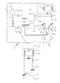
- controller unit for compressors in accordance with the present invention is generally identified with reference numeral 1 in the accompanying drawings.
- Vs the power line with which the circuit is connected (Fig. 1).
- the device 1 in accordance with the present invention is able to operate, due to its "integrated" nature, both to control starting of the compressor (or the induction motor) and to control possible overload conditions of the same during running.
- Device 1 regulates starting of the compressor in order to avoid failures and to inhibit power supply to a starting winding 30 of the compressor at the moment the starting step terminates; in addition during running of the compressor, device 1 prevents the compressor from being powered under critical conditions or conditions of potential danger and also prevents the winding temperatures from becoming too high.
- the control device in accordance with the present invention includes a controller element 3 to regulate starting and running of the compressor via switching means 20, 21.
- the switching means 20, 21 can be respectively activated on a starting winding 30 and a running winding 31 of the compressor to perform the previously mentioned functions.
- controller 3 can be made in many different ways depending on requirements; for example it can consist of microprocessors or logic circuit elements combined with each other based on the particular needs.
- controller 3 comprises a detecting block 40 (adapted to read at least one characteristic magnitude 110 of the compressor), a memory 50 adapted to contain a predetermined number of reference values.
- the memory 50 can be structured in different ways, depending on requirements; it can be an EEPROM, a flash memory, a passive circuit element (a capacitor, a resistor or other), suitably selected so as to have a given reference value (a capacity or resistance value or other), or any configuration of circuit elements the state of which can be changed to store information.
- a processing unit 60 is present which is connected with the detecting block 40 and the memory 50.
- the processing unit 60 processes the characteristic magnitude 110 read by the detecting block 40, to obtain a corresponding main parameter; subsequently this main parameter is compared with at least one of the reference values contained in memory 50 and a control signal 100 is then generated towards the switching means 20, 21 (depending on the result of the just mentioned comparing operation).
- the different control methodologies to be carried out by device 1 during starting of the motor/compressor or during running of the motor/compressor can be performed based on any selection of the type of characteristic magnitudes 110; for instance, during starting of the compressor, current or voltage measurements can be sufficient.
- this characteristic magnitude can be a current flowing through the starting winding 30 and/or the running winding 31, a voltage at the ends of the starting winding 30 and/or the running winding 31; the characteristic magnitude can also be a current or voltage variation rate in the same windings or a ratio between two currents or voltages at different time instants.
- device 1 comprises a voltage or current generator 41, adapted to be suitably connected with the starting winding 30 and/or the running winding 31 to apply a predetermined disturbance voltage "Vd” or disturbance current "Id” thereto; the detecting block 40 then comprises a current or voltage reading unit active on the starting winding 30 and/or the running winding 31 upon application of said disturbance voltage or current.
- the just exemplified disturbance signals can be sent to one or both the compressor windings, depending on requirements; in addition the disturbance currents/voltages can be admitted to the windings before the starting step and during the running step and can be admitted following any time sequences.
- a disturbance current/voltage can be induced in the starting winding 30 during running under steady conditions.
- winding 30 can conveniently be used for carrying out the control method described below.
- the processing unit 60 is able to calculate, depending on the disturbance voltage or current imposed by the voltage or current generator 41 (and on the current or voltage read by a suitable reading unit), the electric resistance of the starting winding 30 and/or running winding 31.
- the processing unit can also calculate the winding temperature using the temperature coefficient of the electric resistance which for a given winding will have known properties.
- the processing unit may also comprise two resistors 60a and 60b connected in series with the starting winding 30 and /or the running winding 31, the main task of which is to detect the current passing through the windings themselves; also present is a circuit 120 for activation of switching means shown as triacs, suitably positioned within controller 3 (Fig. 1).
- generator 41 is set to supply the disturbance voltage/current at predetermined time intervals that can be selected based on different control strategies.
- the present invention may also provide control strategies that are not based on introduction/induction of disturbance currents/voltages, but that may comprise direct measurements of continuous alternating (AC) currents and voltages applied to windings 30 and/or 31.
- AC continuous alternating
- processing of the control signal may merely consist of comparing the current/voltage values directly detected in /at the windings with suitable reference values.
- Direct measurements are particularly advantageous during starting of the motor/compressor; in other words, during starting of the motor/compressor operating sub-steps may be provided in which the currents and /or voltages applied to windings 30 and/or 31 are directly measured, which currents/voltages are in turn immediately compared with the suitable reference values or can be used to define magnitudes of the "derived" type.
- the direct measurements can be also carried out during running under steady conditions of the motor/compressor, as they can for example be used to determine the current flow values in the windings 30 or 31, or to establish the growth or reduction rate of current in time.
- the starting step of the compressor will be now examined; depending on the "starting" signal (e.g. from a thermostat reading a temperature of a refrigerating compartment), the required electric energy can be sent to the control device 1; at this point controller 3 operates on the switching means 20 and/or 21 so as to allow the current to flow to the windings, so as to give rise first to starting and then to running under steady conditions.
- starting e.g. from a thermostat reading a temperature of a refrigerating compartment
- a direct measurement of the current/voltage in the winding disturbance can be made and then the detecting/comparing operation can be performed and possibly a control signal can be emitted.
- This control signal if generated, is sent to the switching means 20 and/or 21 to stop current flow to the windings; in this way the compressor is stopped during the starting step.
- the important steps of the starting control are indicated by the direct current measurements and also indicated are the time intervals (delays “1" and "2") measured starting from the beginning of the motor/compressor starting, at which said direct measurements in succession are carried out.
- the starting control may comprise more than two direct measurements carried out at different time intervals or delays and the algorithm in Fig. 3 is given by way of example only.
- the time interval between two direct measurements can be selected taking into account different factors; for example, this time interval can be sufficiently long to enable all transient electric phenomena occurring in the windings to be neglected but at the same time it must be sufficiently short to enable the operating conditions of the compressor to be determined so as to discover as soon as possible whether the motor has started properly.
- When the compressor is running device 1 can then generate a series of disturbance voltages/currents having the same time duration and at a constant frequency so as to periodically monitor the operating conditions of the compressor.
- the controller 3 following admission of disturbance current/voltage, the controller 3, by means of its sub-components 40, 50 and 60 is able to carry out measurements and comparisons and therefore to determine the operating conditions of the motor/compressor during running.
- the just described succession in time of the current/voltage pulses is not in any case binding; the time intervals can be varied, as well as the duration of the disturbance pulses or even the "waveforms" associated with such disturbance pulses.
- a second disturbance current/voltage can be generated (or a second direct measurement can be carried out) to execute a second measurement of the operating state of the compressor (during running under steady conditions or during starting, respectively).
- the direct measurement can be positioned in time so as to be able to judge whether the compressor motor has reached a sufficient running speed or not.
- a first and/or second time interval can be used to carry out incremental direct measurements . By comparing the measurements carried out after the first and the second intervals, it is possible to determine whether the compressor motor has successfully started.
- the controller 3 can generate a control signal 100 directed to both the switching means 20 and 21 to open them and thus break power supply to the compressor, thereby avoiding overheating and other operating drawbacks.
- Fig 3 also shows how a possible failure of the compressor could be detected after the first time delay (or in other words, after said first time gap), in this case if the winding current was too high the control signal 100 can be generated to open the switching means 20, 21.
- the switching means 20, 21 can also be controlled so as to supply current/voltage to the starting winding 30 alone, to the running winding 31 alone or to both of them; in any case in the present control method a step can be provided for selectively determining which windings are to be supplied during starting or during running under steady conditions.
- control method can involve a first selective-determination step in which, during starting of the motor/compressor, both windings 30 and 31 are supplied from the external power line, followed by a step of excluding the starting winding 30 at the end of starting (which results in the fact that during running only winding 31 carries the current).
- the present method can also carry out a selective choice of the control strategies to be executed on the motor/compressor itself.
- the present method comprises a step of selectively choosing at least between a first control strategy and a second control strategy depending on the operating conditions of the motor and/or the compressor; it will be appreciated that the first control strategy (that may be based on the "direct measurements" of the currents or voltages in the windings) can be selected during starting of the motor and/or the compressor, whereas the second control strategy (that may be conveniently based on the calculation of a resistance parameter of the windings depending on admission of a disturbance current/voltage) can be selected during running of the motor and/or the compressor under steady conditions.
- the first control strategy that may be based on the "direct measurements" of the currents or voltages in the windings
- the second control strategy that may be conveniently based on the calculation of a resistance parameter of the windings depending on admission of a disturbance current/voltage
- the preferred embodiments for the disturbance voltages/currents are of such a nature that the latter have a non-zero average value over a pre-determined working time of the compressor.
- the disturbance currents/voltages are imparted to the windings with a suitable synchronisation.
- this resultant current/voltage due to inductive phenomena, is not coincident with the supply current/voltage coming from an external power line and in most cases it is an alternating current/voltage of a defined frequency (usually 50-60 Hz). Therefore in the specification of the invention this resultant voltage/current is intended as originating from the combination of the supply current/voltage "Vs" to which the inductive effects (or the induced electromotive forces) are added that are given by the variability of the electromagnetic fields typical of electric machines.
- Fig. 4 shows a first form of a disturbance voltage/current in a winding, obtained by activation of the respective switching means close to the end of one negative half cycle of the voltage across the winding.
- the conductivity state of said switching means extends in time until the current through the switch itself goes below a threshold value and the switch turns off (a short time after the current in the winding changes its sign).
- Fig. 5 shows a second form of disturbance voltage/current in a winding, obtained by activating the switching means shortly after the voltage across the winding has reached a negative value It is to be noted again that by suitably selecting the switching means (for example by using triacs) the latter will go on conducting until just after the next change of sign of the current/voltage in the winding.
- the waveforms in Figs. 4 and 5 can be introduced, during running of the compressor, in the starting winding 30, and the disturbance can be synchronised so as to minimise the electric-energy demand for generation of the disturbance current/voltage, to minimise the influences on the running winding 30, and to ensure accurate sampling of the operating compressor conditions.
- Fig. 6 represents a third form of a disturbance voltage/current in a winding, obtained by maintaining the switching means in a conduction state apart from the first part of a negative.
- the waveforms of Figs. 4 and 5 can be used for temperature monitoring in either of the two windings when the compressor motor is not working.
- Fig. 7 represents a fourth form of a disturbance voltage/current in a winding, that is obtained by maintaining the switching means in a conduction state over the whole cycles of the current/voltage in the winding except for a half cycle during which the resultant current/voltage would have a negative value.
- the waveforms in Figs. 6 and 7 can be particularly used in the running winding 31 during operation under steady conditions of the compressor; in these cases the pulse length of the disturbance current/voltage is selected so as to minimise the disturbing effect on the working speed of the compressor motor (but at the same time so as to ensure the necessary measurement accuracy).
- the application frequency of the disturbance currents/voltages can be synchronised with the frequency of the supply current/voltage; preferably, this synchronism condition must be verified in relation to the voltage variation frequency at the ends of the starting windings 30 (at the point it is connected with the respective switching means 20).
- the disturbance currents/voltages can be applied at the most appropriate moments also keeping into account the particular type of motor/compressor; for example, if a running capacitor is present, it is advantageous to apply the disturbance voltage/current to winding 30 when the voltage at the ends of Triac 20 is zero, so as to avoid high switching currents and interferences in the main-parameter measurements.
- the processing unit 60 is also able to verify that the electric resistance calculated based on application of these disturbance currents/voltages (and based on the operations for treatment of the detected parameters following said disturbance) is greater than the reference value and to correspondingly generate the control signal 100, taking account of the fact that a given calculated electric resistance corresponds to a given temperature of the winding under examination.
- the detecting block 40 can be set to detect at least one additional characteristic magnitude of the compressor that will be then processed, stored and compared with the appropriate reference values; in accordance with the present invention this additional characteristic magnitude can be the current flowing in the running winding 31 or the variation rate of said current in time or a direct temperature measurement at or near to the shell of the compressor.
- this additional characteristic magnitude can be particularly useful in all cases in which the so-called "quick dynamics" of the motor/compressor are to be monitored (or in other words, all conditions in which temperatures change very quickly); in these cases the auxiliary characteristic magnitude can advantageously consist of the current (or the growth rate of the current in time, or the ratio of two current values taken at subsequent instants) flowing through the running winding 31 or the start winding 30.
- the present invention can detect the characteristic magnitude 110 under different operating conditions of the windings 30 and/or 31 (under transient de-energising conditions, for example); advantageously, this feature (of the device and the process) can be used to carry out more precise measurements, by stopping supply to a winding and temporarily inserting the disturbance current/voltage thereinto.
- a temporary (or voluntary) de-energising step of a winding can be provided, which step in turn precedes the step of applying the disturbance current/voltage; this temporary de-energising step aims at eliminating the effects due to the currents usually passing through the winding 30 or 31.
- a control method can be for example implemented which cyclically comprises the following steps:
- acceptable duration values of the working interval (or in other words, of the time period corresponding to each turning off/interruption of the supply to the winding) values included between 1 and 30 minutes, and preferably included between 10 and 30 minutes can be stated by way of example.
- a step of dynamically varying the working intervals depending on the specific requirements and/or on measurement of any auxiliary parameters can also be provided.
- the maximum temperature range of a winding can be divided into a plurality of sub-ranges (and each temperature sub-range will be preferably included within a maximum range of admissible temperatures for the motor/compressor), taking care to set suitable correction factors for the measurements carried out in these sub-ranges.
- the switching means 20, 21 is associated in circuit with at least the controller element 3 and is drivable by the latter between a first operating condition (at which it allows a supply current to flow to the starting winding 30 and/or the running winding 31) and a second operating condition (at which it inhibits the supply voltage /current flow to the starting winding 30 and/or the running winding 31).
- each of the switching means 20, 21 has a first end to be connected with a respective end of the starting winding 30 or the running winding 31 and also has a second end set for reception of the control signal 100 that commands the switching means between the first and second operating conditions.
- the switching means 20, 21 comprises at least one semiconductor element that can be a triac; in this case the above mentioned second ends are respectively the gates of these triacs.
- device 1 may also comprise at least one thermal sensor 70 which is operatively interconnected with the controller element 3 to determine an operating temperature; this operating temperature can be a temperature of the outer shell of the compressor, the temperature within the compressor shell or the working temperature of the device 1 itself.
- the controller 3 can act on the triacs 20, 21 to stop the power supply to the compressor.
- a differential or incremental temperature measurement can be also carried out, so as to determine a temperature variation rate (or a temperature ratio at two instants in successions) and possibly act in accordance with pre-established control strategies.
- the thermal sensor 70 is operatively active on the controller unit 3 to determine activation of same depending on predetermined temperature values.
- thermo-sensitive element to be associated with the starting winding 30 and/or the running winding 31 of the compressor; consistently with the above description, this thermo-sensitive element can be operatively active on the switching means 20, 21 to sent it a command signal and establish the operating conditions of same.
- a capacitive element 80 can be connected between the starting winding 30 and running winding 31 of the compressor, or in addition an auxiliary impedance can be connected in series with the starting winding 30 (that depending on the cases can be a fixed resistor or a PTC resistor); it is also possible to include safety means 90 which can be operatively associated with controller 3 and/or the switching means 20, 21 and be in series with the windings 30, 31; this safety means 90 preferably comprises switches and/or triacs and/or fuses.
- a capacitive element 80 can be set to be interposed between the starting winding 30 and running winding 31 of the compressor, or in addition an auxiliary impedance to be connected in circuit with the starting winding 30 (that depending on the cases can be a positive element, a PTC or a capacitor); it is also possible to set safety means 90 operatively associated with controller 3 and/or the switching means 20, 21 and/or to be interposed in circuit between the windings 30, 31; this safety means 90 preferably comprises switches and/or Triacs and/or fuses.
- said device provides a method of controlling starting and/or running of a compressor which (during the compressor starting and/or during the compressor running) comprises the following steps; first of all a characteristic magnitude 110 of the compressor is detected, then this magnitude is processed to obtain a corresponding main parameter; subsequently this main parameter is compared with at least one predetermined and pre-stored reference value and finally, depending on the comparison result, a control signal 100 is generated.
- the succession of steps can be varied depending on whether starting or running is to be controlled; for example, during starting the current/voltage in the windings can be directly measured without inducing electric disturbance, whereas during running of the motor/compressor a disturbance current/voltage can be advantageously introduced at arbitrarily selected time intervals and the resultant electric effects of same can be thus measured (that can be used for example for determining the electric resistance of the windings and consequently the winding temperature).
- the main parameter of the compressor is an electric or thermal parameter of a starting winding 30 and/or a running winding 31 of the compressor
- the characteristic magnitude 110 of the compressor is the magnitude of an electric parameter of the starting winding 30 and/or the running winding 31 and/or an additional thermal parameter.
- the detecting step can take place (preferably when the motor/compressor is running under steady conditions) by applying a predetermined disturbance voltage/current to the ends of the starting winding 30 and/or running winding 31 and reading the resultant voltage/current through the starting winding itself. (i.e. upon application of these predetermined voltage or current).
- the voltage/current disturbance can be carried out on one or both of the windings; in particular, during running of the compressor the starting winding 30 can be stimulated to read the conditions of the running winding 31 (but it is also possible to intervene with the disturbance on both windings); falling within the scope of the present invention can also be control strategies involving insertion of disturbance in the running winding or, once more, in both windings, during starting.
- Selection of the control strategies can be done in a dynamic manner, depending on the actual operating conditions and/or the compressor type.
- the winding temperature changes slowly and because the windings are disposed tightly close to each other their temperatures are substantially the same. If for some reason the current passing through a winding increases, that winding will become hot and it will cause the temperature of the adjacent winding to increase by conduction/convection/radiation. Therefore, in the presence of slow thermal dynamics (i.e. of slow speeds of temperature increase) the winding that is not carrying supply current can advantageously be used for measurement by inducing the disturbance currents/voltages therein and therefore calculating the resistance variation of same; in this case, in fact, the resistance (and temperature) of the two windings can be compared and it is advantageous to use the starting winding to monitor the running winding.
- slow thermal dynamics i.e. of slow speeds of temperature increase
- the above described strategy can be replaced with direct measurements of current in the run and /or start windings.
- the device 1 in accordance with the invention may need an auxiliary timing unit that is connected in circuit with the different components of controller 3 to impose a given synchronism thereto.
- This auxiliary timing unit may consist of an electronic oscillator having a given work frequency (which is selected taking also into account be used to measure the frequency of the supply current/voltage in order to synchronise the different components of controller 3.
- calculation of the electric resistance of one or both windings 30 and/or 31 must be done based on an average value, so as to take into account the alternating mains voltage and induction effects from the varying electromagnetic fields in the motor.
- this calculation comprises either a step of integrating a voltage or current from the winding (starting winding 30 and/or running winding 31) resulting from application of the disturbance current/voltage, or alternatively a step of calculating an average value of a resultant voltage or current in the winding (starting winding 30 and/or running winding 31) following application of the disturbance current /voltage.
- a step of isolating direct current and/or voltage value starting from said step of calculating the average value follows said integrating or averaging step.
- the "average values” or an “integrated values” are preferably determined out over a period of time of one or more complete variation cycles of the alternating voltage across the winding
- the resultant values can then be processed by processing unit 60 to give a "equivalent resistance parameter which can then be processed to give a temperature measurement.
- the main parameter (that can be considered as equivalent to a hypothetical "equivalent electric resistance" that would be measured if a direct current or voltage were present in windings 30 and/or 31) actually is a parameter which minimises the effects of the alternating current/voltage supply and which therefore can be used to provide a realistic measurement of the temperature of the winding itself).
- the present method advantageously comprises a sub-step of calculating a "parameter of direct-current equivalent resistance" that is practically calculated when the motor and/or the compressor is powered by a supply voltage/current varying in time.
- the "parameter of direct-current equivalent resistance" defined above is practically treated, at least in terms of calculation and processing by unit 60, as a resistance of the starting winding 30 and/or the running winding 31.
- this parameter of direct-current equivalent resistance is calculated at least depending on the predetermined disturbance voltage and/or current applied to windings 30 and/or 31.
- controller 3 compares the thus obtained average value of the resistance with the contents of its memory 50 or, in other words, the comparing step comprises a sub-step of verifying whether the calculated electric resistance is greater than the predetermined pre-stored reference value or not.
- device 1 can be advantageously made independent and be applied to any type of compressor (or in other words, irrespective of the current/voltage/resistance values found in the different types of motors/compressors).
- reference value/s can be loaded on memory 50 in several different manners; for example, they can be preloaded in the respective storage module still before assembling the device 1, or they can be directly read by the compressor during a "test stroke".
- the reference value may be obtained through a preliminary acquisition step; this preliminary acquisition step being carried out by detecting an auxiliary characteristic magnitude of the compressor winding and processing it so as to obtain said predetermined reference value, then the result of this operation is stored in a memory 50 as "reference value".
- the operation can be performed in different ways depending on requirements.
- the motor/compressor can be run for a predetermined period of time (so as to reach a steady operating condition that is substantially stabilised in terms of temperatures and currents/voltages), then the device 1 can carry out a predetermined number of measurements to detect a series of characteristic magnitudes that can be input to memory 50 and stored thereon as reference values.
- the reference values can be calculated by an external calculation system that will operate based on its knowledge of a "stabilised” temperature of the motor/compressor; following this "external” calculation, the calculated values are introduced into the memory of device 1.
- processing unit 60 itself should calculate some values under predetermined temperature conditions of the motor/compressor, and store them in an independent manner; in this way the reference values thus obtained will be calculated taking into account the same tolerances in detecting the characteristic magnitudes 110 during operation of controller 3.
- both the stored reference values and the operating parameters can be of various types (they can be the current in windings 30 and/or 31, or the temperatures of the outer shell in the motor/compressor, or the temperatures of the surrounding environment of the motor/compressor and so on) and can also be derived magnitudes, or magnitude ratios or incremental measurements.
- the method hitherto described can be applied cyclically during operation under steady conditions of a compressor, so as to carry out a continuous monitoring of the operating conditions.
- the control method can be repeated at predetermined (arbitrary) time intervals, which in turn can be dynamically varied depending on the operating conditions themselves.
- the fact that the detecting operation is performed with a periodical character is particularly advantageous in terms of reliability of the detection itself.
- a long time interval can be provided between two measurements in succession; on the contrary, if the temperature of the compressor shell (or the temperature of the windings) is close to a given threshold limit, measurements can be done with closer times so as to follow the compressor operation with greater accuracy.
- a step of activating the controller 3 depending on an external signal can be present; in other words, the control method can be put into practice (or correspondingly the control device 1 can be operated) only when the operating conditions of the apparatus call for it.
- controller 3 can be always connected with the external electric power, and the thermostat can send a signal to directly switch the compressor on or off.
- the device 1 in accordance with the invention operation of the control method depends on an "external" signal (relating to temperature, such as a cooling request from a refrigerating compartment).
- device 1 can cause it to be "locked-out", by cutting the supply current/voltage to the running winding 31 or the starting winding 30. It is also to be noted that this locked-out condition can be reversible or irreversible, depending on the gravity of the situation giving rise to it.
- the locked-out condition can be generated on detection of current in the winding which is too high, said detection being suitably made by controller 3.
- the controller can operate in such a manner as to cause a fuse to blow or the power supply from the electric power line to be excluded.
- Restoration of the operating conditions can be managed in an independent manner by controller 3 (based on possible subsequent measurements of the compressor conditions) or based on a manual reset by an operator.
- the controller 3 can decide whether to set an irreversible lock-out (when a too high current is detected on starting, for example) or to set a reversible lock-out (for example when an anomalous current is detected which however is not high enough to be a critical value).
- the present method can provide for other controls; for example before starting, a preliminary control can be carried out to verify adequacy of the supply voltage and/or current, or also a preliminary control can be carried out to verify whether the compressor was previously in operation and/or has not yet become sufficiently cold.
- controller 3 can carry out different types of monitoring operations on the windings 30 and/or 31 of a compressor; for instance the following can be measured:
- controller 3 allows continuation of the compressor running until for example the thermostat of the refrigerating compartment detects that a sufficient cooling has been reached and cuts power supply; in these cases the controller can provide for a waiting step by setting a predetermined time delay (two minutes, for example) before which the compressor cannot start again; in this way the risks of a condition of "jammed rotor" on restarting of the compressor are reduced.
- a "jammed rotor" condition can be caused by a temporary thermodynamic unbalance of the gas used in the cooling circuit which results in excessive pressure difference across the compressor. In these cases it is necessary to allow the pressure difference to recover by introducing a safety time delay using controller 3 and the switching means to temporarily cut the power supply to windings 30 and/or 31.
- the present invention is also capable of optimising the modalities for change of state of the Triac.
- an element of the PTC type to pilot a Triac (that in turn enables or inhibits flowing of a current on the starting winding 30)
- three different operating moments can be distinguished; a first operating field in which the PTC resistance goes low (and in which the Triac changes its state at a low phase angle, substantially transferring the full electric power from the power line to the starting winding 30); a second operating field in which the resistance quickly grows (and in which the just mentioned phase angle increases so that transfer of electric energy to winding 30 decreases in quantity and is submitted to offsetting in time); a third operating field in which the resistance goes high and the Triac reaches a condition of "switched off”.
- the intervention sensitivity of the gate of a Triac is usually different with respect to the supply voltage and/or current signal; due to this sensitivity difference even in the high-resistance operating field of the PTC the Triac is subjected to changes of state (from "open” to "closed” and vice versa, in a permanent manner over a limited period of time).
- the present invention advantageously comprises equalisation means 200 operatively active on the switching means 20 and/or 21; and preferably active on the second ends of the switching means itself; this equalisation means 200 practically minimises the sensitivity variations of a gate in a Triac thereby greatly reducing (and even eliminating) the undesirable "half part firing".
- the present invention can implement a method minimising the gate sensitivity so as to modify the sensitivity of the gate itself at the positive half cycles of the supply current/voltage making it equal to the gate sensitivity at the negative half cycles of the supply current/voltage.
- the equalisation means 200 can consist of a suitable circuit branch (to be seen in Fig. 8) having a diode (or an equivalent circuit means) 201 that practically sends to the ground the current directed to the Triac gate at the half cycles in which the gate sensitivity is at its maximum degree.
- resistive elements 202 and/or 203 and/or 204 it is also possible to detect the presence of resistive elements 202 and/or 203 and/or 204, depending on requirements; in particular it is possible to arrange a resistive element in series with the PTC 205 in order to regulate the energising time of the winding 30 or 31 piloted by the Triac 20 or 21.
- an object of the present invention is a compressor, in particular for refrigerating apparatus, comprising a control device 1 having the structure and operating in accordance with the method described above.
- the characteristic magnitude 110 and/or auxiliary characteristic magnitude and/or main parameter can be electric or thermal magnitudes, or variation rates in time of thermal or electric magnitudes, or ratios between thermal or electric magnitudes measured at time instants in succession, or ratios between thermal or electric magnitudes measured in the starting winding 30 and/or the running winding 31 and electric or thermal reference magnitudes, depending on the specific requirements.
- the invention achieves important advantages over the prior art.
- control unit can be programmed so as to carry out different control strategies or even to combine or select one or more operating modalities in an adaptable manner depending on the specific requirements.
- control unit for compressors in accordance with the present invention can minimise power consumption both during the starting and the running phases.
- control unit for compressors in accordance with the present invention can also be provided with a control system of the starting step operating at very low energy consumption, above all during the step in which the compressor works under steady conditions.
- control unit can be used to directly detect temperature increases in the compressor, which is advantageous in terms of adaptability and overall safety in operation.
- overload-control and power-control functions can be integrated into a single device, which is very advantageous as regards manufacturing costs, construction simplicity and reliability.
Landscapes
- Engineering & Computer Science (AREA)
- Power Engineering (AREA)
- Control Of Ac Motors In General (AREA)
- Control Of Positive-Displacement Pumps (AREA)
- Motor And Converter Starters (AREA)
- Control Of Multiple Motors (AREA)
Applications Claiming Priority (4)
| Application Number | Priority Date | Filing Date | Title |
|---|---|---|---|
| ITMI20031371 | 2003-07-04 | ||
| IT001371A ITMI20031371A1 (it) | 2003-07-04 | 2003-07-04 | Gruppo controllore per compressori, in particolare per compressori di impianti frigoriferi. |
| ITMI20031532 | 2003-07-25 | ||
| ITMI20031532 ITMI20031532A1 (it) | 2003-07-25 | 2003-07-25 | Dispositivo controllore, in particolare per motori ad induzione e ancor piu' in particolare per compressori di impianti frigoriferi |
Publications (3)
| Publication Number | Publication Date |
|---|---|
| EP1494346A2 true EP1494346A2 (de) | 2005-01-05 |
| EP1494346A3 EP1494346A3 (de) | 2010-10-06 |
| EP1494346B1 EP1494346B1 (de) | 2013-01-30 |
Family
ID=33436355
Family Applications (1)
| Application Number | Title | Priority Date | Filing Date |
|---|---|---|---|
| EP04102917A Expired - Lifetime EP1494346B1 (de) | 2003-07-04 | 2004-06-23 | Steuerungsgerät, insbesondere für einen Asynchronmotor und mehr insbesondere für Kompressoren von kältetechnischen Apparaten |
Country Status (1)
| Country | Link |
|---|---|
| EP (1) | EP1494346B1 (de) |
Cited By (8)
| Publication number | Priority date | Publication date | Assignee | Title |
|---|---|---|---|---|
| WO2007074092A3 (en) * | 2005-12-29 | 2007-09-07 | Arcelik As | A motor |
| DE102006021256A1 (de) * | 2006-04-28 | 2007-11-08 | Danfoss Compressors Gmbh | Motorstartschaltkreis |
| US7777992B2 (en) | 2006-11-07 | 2010-08-17 | Danfoss Compressors Gmbh | Motor start circuit |
| US7777438B2 (en) | 2006-07-19 | 2010-08-17 | Danfoss Compressors Gmbh | Motor start circuit |
| EP2458728A2 (de) | 2010-11-30 | 2012-05-30 | B.D.G. el S.r.l. | Motorsteuerungssysteme |
| CN112994575A (zh) * | 2019-12-17 | 2021-06-18 | 青岛海尔空调电子有限公司 | 三相压缩机的绕组温度确定方法、启动方法以及空调器 |
| CN116222079A (zh) * | 2023-03-16 | 2023-06-06 | 海信冰箱有限公司 | 一种冰箱及其压缩机控制方法 |
| CN118100701A (zh) * | 2024-04-12 | 2024-05-28 | 深圳山河半导体科技有限公司 | 三相六线直流无刷电机差放驱动方法、系统、介质和设备 |
Citations (4)
| Publication number | Priority date | Publication date | Assignee | Title |
|---|---|---|---|---|
| EP0031688A2 (de) | 1979-12-28 | 1981-07-08 | Myson Group Limited | Anlaufsteuerung für einen Elektromotor |
| JPH05244787A (ja) | 1992-02-27 | 1993-09-21 | Murata Mfg Co Ltd | 単相交流誘導モーターの起動回路 |
| US5488834A (en) | 1993-04-14 | 1996-02-06 | Empresa Brasileira De Compressores S/A - Embraco | Control circuit for a refrigerating system |
| EP1100190A2 (de) | 1999-11-12 | 2001-05-16 | Lg Electronics Inc. | Vorrichtung und Verfahren zur Steuerung des Versorgungstroms und der statischen Kapazität eines Kompressors |
Family Cites Families (1)
| Publication number | Priority date | Publication date | Assignee | Title |
|---|---|---|---|---|
| US5483139A (en) * | 1994-03-14 | 1996-01-09 | General Electric Company | Motor start, reverse and protection system without a starting capacitor |
-
2004
- 2004-06-23 EP EP04102917A patent/EP1494346B1/de not_active Expired - Lifetime
Patent Citations (4)
| Publication number | Priority date | Publication date | Assignee | Title |
|---|---|---|---|---|
| EP0031688A2 (de) | 1979-12-28 | 1981-07-08 | Myson Group Limited | Anlaufsteuerung für einen Elektromotor |
| JPH05244787A (ja) | 1992-02-27 | 1993-09-21 | Murata Mfg Co Ltd | 単相交流誘導モーターの起動回路 |
| US5488834A (en) | 1993-04-14 | 1996-02-06 | Empresa Brasileira De Compressores S/A - Embraco | Control circuit for a refrigerating system |
| EP1100190A2 (de) | 1999-11-12 | 2001-05-16 | Lg Electronics Inc. | Vorrichtung und Verfahren zur Steuerung des Versorgungstroms und der statischen Kapazität eines Kompressors |
Cited By (12)
| Publication number | Priority date | Publication date | Assignee | Title |
|---|---|---|---|---|
| WO2007074092A3 (en) * | 2005-12-29 | 2007-09-07 | Arcelik As | A motor |
| DE102006021256A1 (de) * | 2006-04-28 | 2007-11-08 | Danfoss Compressors Gmbh | Motorstartschaltkreis |
| US7630180B2 (en) | 2006-04-28 | 2009-12-08 | Danfoss Compressors Gmbh | Motor starter circuit |
| US7777438B2 (en) | 2006-07-19 | 2010-08-17 | Danfoss Compressors Gmbh | Motor start circuit |
| US7777992B2 (en) | 2006-11-07 | 2010-08-17 | Danfoss Compressors Gmbh | Motor start circuit |
| EP2458728A2 (de) | 2010-11-30 | 2012-05-30 | B.D.G. el S.r.l. | Motorsteuerungssysteme |
| EP2458728A3 (de) * | 2010-11-30 | 2018-04-11 | B.D.G. el S.r.l. | Motorsteuerungssysteme |
| EP3447896A1 (de) | 2010-11-30 | 2019-02-27 | B.D.G. el S.r.l. | Motorsteuerungssysteme |
| CN112994575A (zh) * | 2019-12-17 | 2021-06-18 | 青岛海尔空调电子有限公司 | 三相压缩机的绕组温度确定方法、启动方法以及空调器 |
| CN116222079A (zh) * | 2023-03-16 | 2023-06-06 | 海信冰箱有限公司 | 一种冰箱及其压缩机控制方法 |
| CN118100701A (zh) * | 2024-04-12 | 2024-05-28 | 深圳山河半导体科技有限公司 | 三相六线直流无刷电机差放驱动方法、系统、介质和设备 |
| CN118100701B (zh) * | 2024-04-12 | 2024-09-24 | 深圳山河半导体科技有限公司 | 三相六线直流无刷电机差放驱动方法、系统、介质和设备 |
Also Published As
| Publication number | Publication date |
|---|---|
| EP1494346B1 (de) | 2013-01-30 |
| EP1494346A3 (de) | 2010-10-06 |
Similar Documents
| Publication | Publication Date | Title |
|---|---|---|
| US8084984B2 (en) | System and method for monitoring and controlling stator winding temperature in a de-energized AC motor | |
| US5808441A (en) | Microprocessor based motor control system with phase difference detection | |
| EP1118050B1 (de) | Digitaler mehrpunkttemperaturregler | |
| EP3447896B1 (de) | Motorsteuerungssysteme | |
| US3959692A (en) | Monitor and controller for heating a resistive element | |
| US20040244389A1 (en) | Integrated refrigeration control | |
| EP1494346B1 (de) | Steuerungsgerät, insbesondere für einen Asynchronmotor und mehr insbesondere für Kompressoren von kältetechnischen Apparaten | |
| CA1318352C (en) | Overload protection circuit for solid state switch | |
| US20150364976A1 (en) | Overheat detection device for electric motor equipped with multiple ptc thermistors | |
| EP2604929B1 (de) | Kochvorrichtung und Verfahren zur Erkennung der Betriebszustände einer Kochvorrichtung | |
| FI106652B (fi) | Menetelmä ja kytkentäjärjestely sähköisesti kuumennettujen laitteiden käyttölämpötilan valvontaa ja rajoittamista varten sekä tämän menetelmän käyttö | |
| EP2474799A2 (de) | Temperaturkontrollsysteme | |
| CN1095312C (zh) | 防止微波炉无负载工作的方法 | |
| US8692525B2 (en) | Electrical power tool for operating with alternating current | |
| RU2610443C2 (ru) | Управление электрического подогревателя всасываемого воздуха двигателя внутреннего сгорания | |
| CN1041893C (zh) | 反相器烹调器的消耗电功率测定装置和方法 | |
| KR101466861B1 (ko) | 스팀오븐의 대류팬 제어방법 | |
| EP1966880B1 (de) | Motor | |
| CN110384388A (zh) | 烹饪器具的控制方法及系统、烹饪器具 | |
| EP1327776A2 (de) | Überlastregelung eines Kompressorsystems | |
| KR101752963B1 (ko) | 영구소손 계자코일 우회장치 | |
| KR101745113B1 (ko) | 히터를 이용한 고온초전도 코일 보호장치 | |
| KR100578363B1 (ko) | 냉장고의 제상제어회로 | |
| JP3119350B2 (ja) | 断線警報器 | |
| KR20250130215A (ko) | 온도 제어형 기기를 위한 제로 크로스 제어 |
Legal Events
| Date | Code | Title | Description |
|---|---|---|---|
| PUAI | Public reference made under article 153(3) epc to a published international application that has entered the european phase |
Free format text: ORIGINAL CODE: 0009012 |
|
| AK | Designated contracting states |
Kind code of ref document: A2 Designated state(s): AT BE BG CH CY CZ DE DK EE ES FI FR GB GR HU IE IT LI LU MC NL PL PT RO SE SI SK TR |
|
| AX | Request for extension of the european patent |
Extension state: AL HR LT LV MK |
|
| PUAL | Search report despatched |
Free format text: ORIGINAL CODE: 0009013 |
|
| AK | Designated contracting states |
Kind code of ref document: A3 Designated state(s): AT BE BG CH CY CZ DE DK EE ES FI FR GB GR HU IE IT LI LU MC NL PL PT RO SE SI SK TR |
|
| AX | Request for extension of the european patent |
Extension state: AL HR LT LV MK |
|
| 17P | Request for examination filed |
Effective date: 20110401 |
|
| AKX | Designation fees paid |
Designated state(s): AT BE BG CH CY CZ DE DK EE ES FI FR GB GR HU IE IT LI LU MC NL PL PT RO SE SI SK TR |
|
| 17Q | First examination report despatched |
Effective date: 20110713 |
|
| REG | Reference to a national code |
Ref country code: DE Ref legal event code: R079 Ref document number: 602004040916 Country of ref document: DE Free format text: PREVIOUS MAIN CLASS: H02P0001440000 Ipc: H02P0025040000 |
|
| RIC1 | Information provided on ipc code assigned before grant |
Ipc: H02P 25/04 20060101AFI20120710BHEP Ipc: H02P 29/02 20060101ALI20120710BHEP Ipc: H02P 1/44 20060101ALI20120710BHEP |
|
| GRAP | Despatch of communication of intention to grant a patent |
Free format text: ORIGINAL CODE: EPIDOSNIGR1 |
|
| GRAS | Grant fee paid |
Free format text: ORIGINAL CODE: EPIDOSNIGR3 |
|
| GRAA | (expected) grant |
Free format text: ORIGINAL CODE: 0009210 |
|
| AK | Designated contracting states |
Kind code of ref document: B1 Designated state(s): AT BE BG CH CY CZ DE DK EE ES FI FR GB GR HU IE IT LI LU MC NL PL PT RO SE SI SK TR |
|
| REG | Reference to a national code |
Ref country code: GB Ref legal event code: FG4D |
|
| REG | Reference to a national code |
Ref country code: CH Ref legal event code: EP |
|
| REG | Reference to a national code |
Ref country code: AT Ref legal event code: REF Ref document number: 595867 Country of ref document: AT Kind code of ref document: T Effective date: 20130215 Ref country code: CH Ref legal event code: EP |
|
| REG | Reference to a national code |
Ref country code: IE Ref legal event code: FG4D |
|
| REG | Reference to a national code |
Ref country code: DE Ref legal event code: R096 Ref document number: 602004040916 Country of ref document: DE Effective date: 20130328 |
|
| REG | Reference to a national code |
Ref country code: AT Ref legal event code: MK05 Ref document number: 595867 Country of ref document: AT Kind code of ref document: T Effective date: 20130130 |
|
| REG | Reference to a national code |
Ref country code: NL Ref legal event code: VDEP Effective date: 20130130 |
|
| PG25 | Lapsed in a contracting state [announced via postgrant information from national office to epo] |
Ref country code: ES Free format text: LAPSE BECAUSE OF FAILURE TO SUBMIT A TRANSLATION OF THE DESCRIPTION OR TO PAY THE FEE WITHIN THE PRESCRIBED TIME-LIMIT Effective date: 20130511 Ref country code: BE Free format text: LAPSE BECAUSE OF FAILURE TO SUBMIT A TRANSLATION OF THE DESCRIPTION OR TO PAY THE FEE WITHIN THE PRESCRIBED TIME-LIMIT Effective date: 20130130 Ref country code: SE Free format text: LAPSE BECAUSE OF FAILURE TO SUBMIT A TRANSLATION OF THE DESCRIPTION OR TO PAY THE FEE WITHIN THE PRESCRIBED TIME-LIMIT Effective date: 20130130 Ref country code: AT Free format text: LAPSE BECAUSE OF FAILURE TO SUBMIT A TRANSLATION OF THE DESCRIPTION OR TO PAY THE FEE WITHIN THE PRESCRIBED TIME-LIMIT Effective date: 20130130 Ref country code: CY Free format text: LAPSE BECAUSE OF FAILURE TO SUBMIT A TRANSLATION OF THE DESCRIPTION OR TO PAY THE FEE WITHIN THE PRESCRIBED TIME-LIMIT Effective date: 20130130 Ref country code: BG Free format text: LAPSE BECAUSE OF FAILURE TO SUBMIT A TRANSLATION OF THE DESCRIPTION OR TO PAY THE FEE WITHIN THE PRESCRIBED TIME-LIMIT Effective date: 20130430 |
|
| PG25 | Lapsed in a contracting state [announced via postgrant information from national office to epo] |
Ref country code: FI Free format text: LAPSE BECAUSE OF FAILURE TO SUBMIT A TRANSLATION OF THE DESCRIPTION OR TO PAY THE FEE WITHIN THE PRESCRIBED TIME-LIMIT Effective date: 20130130 Ref country code: PL Free format text: LAPSE BECAUSE OF FAILURE TO SUBMIT A TRANSLATION OF THE DESCRIPTION OR TO PAY THE FEE WITHIN THE PRESCRIBED TIME-LIMIT Effective date: 20130130 Ref country code: NL Free format text: LAPSE BECAUSE OF FAILURE TO SUBMIT A TRANSLATION OF THE DESCRIPTION OR TO PAY THE FEE WITHIN THE PRESCRIBED TIME-LIMIT Effective date: 20130130 Ref country code: SI Free format text: LAPSE BECAUSE OF FAILURE TO SUBMIT A TRANSLATION OF THE DESCRIPTION OR TO PAY THE FEE WITHIN THE PRESCRIBED TIME-LIMIT Effective date: 20130130 Ref country code: GR Free format text: LAPSE BECAUSE OF FAILURE TO SUBMIT A TRANSLATION OF THE DESCRIPTION OR TO PAY THE FEE WITHIN THE PRESCRIBED TIME-LIMIT Effective date: 20130501 Ref country code: PT Free format text: LAPSE BECAUSE OF FAILURE TO SUBMIT A TRANSLATION OF THE DESCRIPTION OR TO PAY THE FEE WITHIN THE PRESCRIBED TIME-LIMIT Effective date: 20130530 |
|
| PG25 | Lapsed in a contracting state [announced via postgrant information from national office to epo] |
Ref country code: SK Free format text: LAPSE BECAUSE OF FAILURE TO SUBMIT A TRANSLATION OF THE DESCRIPTION OR TO PAY THE FEE WITHIN THE PRESCRIBED TIME-LIMIT Effective date: 20130130 Ref country code: DK Free format text: LAPSE BECAUSE OF FAILURE TO SUBMIT A TRANSLATION OF THE DESCRIPTION OR TO PAY THE FEE WITHIN THE PRESCRIBED TIME-LIMIT Effective date: 20130130 Ref country code: CZ Free format text: LAPSE BECAUSE OF FAILURE TO SUBMIT A TRANSLATION OF THE DESCRIPTION OR TO PAY THE FEE WITHIN THE PRESCRIBED TIME-LIMIT Effective date: 20130130 Ref country code: RO Free format text: LAPSE BECAUSE OF FAILURE TO SUBMIT A TRANSLATION OF THE DESCRIPTION OR TO PAY THE FEE WITHIN THE PRESCRIBED TIME-LIMIT Effective date: 20130130 Ref country code: EE Free format text: LAPSE BECAUSE OF FAILURE TO SUBMIT A TRANSLATION OF THE DESCRIPTION OR TO PAY THE FEE WITHIN THE PRESCRIBED TIME-LIMIT Effective date: 20130130 |
|
| PLBE | No opposition filed within time limit |
Free format text: ORIGINAL CODE: 0009261 |
|
| STAA | Information on the status of an ep patent application or granted ep patent |
Free format text: STATUS: NO OPPOSITION FILED WITHIN TIME LIMIT |
|
| RAP2 | Party data changed (patent owner data changed or rights of a patent transferred) |
Owner name: B.D.G. EL S.R.L. |
|
| 26N | No opposition filed |
Effective date: 20131031 |
|
| PG25 | Lapsed in a contracting state [announced via postgrant information from national office to epo] |
Ref country code: MC Free format text: LAPSE BECAUSE OF FAILURE TO SUBMIT A TRANSLATION OF THE DESCRIPTION OR TO PAY THE FEE WITHIN THE PRESCRIBED TIME-LIMIT Effective date: 20130130 |
|
| REG | Reference to a national code |
Ref country code: CH Ref legal event code: PL |
|
| REG | Reference to a national code |
Ref country code: DE Ref legal event code: R097 Ref document number: 602004040916 Country of ref document: DE Effective date: 20131031 |
|
| REG | Reference to a national code |
Ref country code: IE Ref legal event code: MM4A |
|
| PG25 | Lapsed in a contracting state [announced via postgrant information from national office to epo] |
Ref country code: IE Free format text: LAPSE BECAUSE OF NON-PAYMENT OF DUE FEES Effective date: 20130623 Ref country code: LI Free format text: LAPSE BECAUSE OF NON-PAYMENT OF DUE FEES Effective date: 20130630 Ref country code: CH Free format text: LAPSE BECAUSE OF NON-PAYMENT OF DUE FEES Effective date: 20130630 |
|
| PG25 | Lapsed in a contracting state [announced via postgrant information from national office to epo] |
Ref country code: TR Free format text: LAPSE BECAUSE OF FAILURE TO SUBMIT A TRANSLATION OF THE DESCRIPTION OR TO PAY THE FEE WITHIN THE PRESCRIBED TIME-LIMIT Effective date: 20130130 |
|
| PG25 | Lapsed in a contracting state [announced via postgrant information from national office to epo] |
Ref country code: LU Free format text: LAPSE BECAUSE OF NON-PAYMENT OF DUE FEES Effective date: 20130623 Ref country code: HU Free format text: LAPSE BECAUSE OF FAILURE TO SUBMIT A TRANSLATION OF THE DESCRIPTION OR TO PAY THE FEE WITHIN THE PRESCRIBED TIME-LIMIT; INVALID AB INITIO Effective date: 20040623 |
|
| REG | Reference to a national code |
Ref country code: FR Ref legal event code: PLFP Year of fee payment: 13 |
|
| REG | Reference to a national code |
Ref country code: FR Ref legal event code: PLFP Year of fee payment: 14 |
|
| REG | Reference to a national code |
Ref country code: FR Ref legal event code: PLFP Year of fee payment: 15 |
|
| PGFP | Annual fee paid to national office [announced via postgrant information from national office to epo] |
Ref country code: FR Payment date: 20230622 Year of fee payment: 20 Ref country code: DE Payment date: 20230627 Year of fee payment: 20 |
|
| PGFP | Annual fee paid to national office [announced via postgrant information from national office to epo] |
Ref country code: IT Payment date: 20230619 Year of fee payment: 20 Ref country code: GB Payment date: 20230620 Year of fee payment: 20 |
|
| P01 | Opt-out of the competence of the unified patent court (upc) registered |
Effective date: 20240320 |
|
| REG | Reference to a national code |
Ref country code: DE Ref legal event code: R071 Ref document number: 602004040916 Country of ref document: DE |
|
| PG25 | Lapsed in a contracting state [announced via postgrant information from national office to epo] |
Ref country code: GB Free format text: LAPSE BECAUSE OF EXPIRATION OF PROTECTION Effective date: 20240622 |
|
| REG | Reference to a national code |
Ref country code: GB Ref legal event code: PE20 Expiry date: 20240622 |
|
| PG25 | Lapsed in a contracting state [announced via postgrant information from national office to epo] |
Ref country code: GB Free format text: LAPSE BECAUSE OF EXPIRATION OF PROTECTION Effective date: 20240622 |