EP2458728A2 - Motorsteuerungssysteme - Google Patents
Motorsteuerungssysteme Download PDFInfo
- Publication number
- EP2458728A2 EP2458728A2 EP11190327A EP11190327A EP2458728A2 EP 2458728 A2 EP2458728 A2 EP 2458728A2 EP 11190327 A EP11190327 A EP 11190327A EP 11190327 A EP11190327 A EP 11190327A EP 2458728 A2 EP2458728 A2 EP 2458728A2
- Authority
- EP
- European Patent Office
- Prior art keywords
- motor
- winding
- current
- starting
- temperature
- Prior art date
- Legal status (The legal status is an assumption and is not a legal conclusion. Google has not performed a legal analysis and makes no representation as to the accuracy of the status listed.)
- Withdrawn
Links
- 238000004804 winding Methods 0.000 claims abstract description 303
- 238000005265 energy consumption Methods 0.000 claims abstract description 57
- 230000006698 induction Effects 0.000 claims abstract description 37
- 230000001419 dependent effect Effects 0.000 claims abstract description 22
- 230000036413 temperature sense Effects 0.000 claims abstract description 22
- 230000001965 increasing effect Effects 0.000 claims description 12
- 238000001514 detection method Methods 0.000 claims description 4
- 238000000034 method Methods 0.000 description 83
- 230000006870 function Effects 0.000 description 54
- 230000008569 process Effects 0.000 description 32
- 238000005057 refrigeration Methods 0.000 description 25
- 238000013021 overheating Methods 0.000 description 20
- 230000008901 benefit Effects 0.000 description 14
- 230000008859 change Effects 0.000 description 12
- 230000009467 reduction Effects 0.000 description 12
- 238000013459 approach Methods 0.000 description 11
- 238000013461 design Methods 0.000 description 11
- 230000001052 transient effect Effects 0.000 description 10
- 239000003990 capacitor Substances 0.000 description 9
- 230000004907 flux Effects 0.000 description 9
- 230000001012 protector Effects 0.000 description 8
- 239000012530 fluid Substances 0.000 description 7
- 230000001351 cycling effect Effects 0.000 description 6
- 238000005259 measurement Methods 0.000 description 6
- 230000006399 behavior Effects 0.000 description 5
- 238000004364 calculation method Methods 0.000 description 5
- 230000000694 effects Effects 0.000 description 5
- 238000010438 heat treatment Methods 0.000 description 5
- 230000004044 response Effects 0.000 description 5
- 238000005070 sampling Methods 0.000 description 5
- 238000012360 testing method Methods 0.000 description 5
- 239000004020 conductor Substances 0.000 description 4
- 238000001816 cooling Methods 0.000 description 4
- 238000005516 engineering process Methods 0.000 description 4
- 230000004913 activation Effects 0.000 description 3
- 230000002411 adverse Effects 0.000 description 3
- 230000009286 beneficial effect Effects 0.000 description 3
- 238000004519 manufacturing process Methods 0.000 description 3
- 238000010079 rubber tapping Methods 0.000 description 3
- 230000001360 synchronised effect Effects 0.000 description 3
- 239000002699 waste material Substances 0.000 description 3
- 238000012935 Averaging Methods 0.000 description 2
- XEEYBQQBJWHFJM-UHFFFAOYSA-N Iron Chemical compound [Fe] XEEYBQQBJWHFJM-UHFFFAOYSA-N 0.000 description 2
- 238000011161 development Methods 0.000 description 2
- 230000001939 inductive effect Effects 0.000 description 2
- 230000010363 phase shift Effects 0.000 description 2
- 238000012545 processing Methods 0.000 description 2
- 239000003507 refrigerant Substances 0.000 description 2
- 239000004065 semiconductor Substances 0.000 description 2
- 230000035945 sensitivity Effects 0.000 description 2
- 238000012546 transfer Methods 0.000 description 2
- RYGMFSIKBFXOCR-UHFFFAOYSA-N Copper Chemical compound [Cu] RYGMFSIKBFXOCR-UHFFFAOYSA-N 0.000 description 1
- 230000005355 Hall effect Effects 0.000 description 1
- 230000005534 acoustic noise Effects 0.000 description 1
- 230000003321 amplification Effects 0.000 description 1
- 238000004458 analytical method Methods 0.000 description 1
- 238000006243 chemical reaction Methods 0.000 description 1
- 230000006835 compression Effects 0.000 description 1
- 238000007906 compression Methods 0.000 description 1
- 238000010276 construction Methods 0.000 description 1
- 238000007796 conventional method Methods 0.000 description 1
- 229910052802 copper Inorganic materials 0.000 description 1
- 239000010949 copper Substances 0.000 description 1
- 238000012937 correction Methods 0.000 description 1
- 230000008878 coupling Effects 0.000 description 1
- 238000010168 coupling process Methods 0.000 description 1
- 238000005859 coupling reaction Methods 0.000 description 1
- 125000004122 cyclic group Chemical group 0.000 description 1
- 230000003111 delayed effect Effects 0.000 description 1
- 238000010586 diagram Methods 0.000 description 1
- 206010022000 influenza Diseases 0.000 description 1
- 230000010354 integration Effects 0.000 description 1
- 229910052742 iron Inorganic materials 0.000 description 1
- 238000012986 modification Methods 0.000 description 1
- 230000004048 modification Effects 0.000 description 1
- 238000012544 monitoring process Methods 0.000 description 1
- 238000003199 nucleic acid amplification method Methods 0.000 description 1
- 238000011017 operating method Methods 0.000 description 1
- 238000003825 pressing Methods 0.000 description 1
- 230000003252 repetitive effect Effects 0.000 description 1
- 238000010845 search algorithm Methods 0.000 description 1
- 238000011896 sensitive detection Methods 0.000 description 1
- 238000000926 separation method Methods 0.000 description 1
- 239000007858 starting material Substances 0.000 description 1
- 230000002459 sustained effect Effects 0.000 description 1
- 230000036962 time dependent Effects 0.000 description 1
Images





Classifications
-
- H—ELECTRICITY
- H02—GENERATION; CONVERSION OR DISTRIBUTION OF ELECTRIC POWER
- H02P—CONTROL OR REGULATION OF ELECTRIC MOTORS, ELECTRIC GENERATORS OR DYNAMO-ELECTRIC CONVERTERS; CONTROLLING TRANSFORMERS, REACTORS OR CHOKE COILS
- H02P1/00—Arrangements for starting electric motors or dynamo-electric converters
- H02P1/16—Arrangements for starting electric motors or dynamo-electric converters for starting dynamo-electric motors or dynamo-electric converters
- H02P1/42—Arrangements for starting electric motors or dynamo-electric converters for starting dynamo-electric motors or dynamo-electric converters for starting an individual single-phase induction motor
-
- F—MECHANICAL ENGINEERING; LIGHTING; HEATING; WEAPONS; BLASTING
- F25—REFRIGERATION OR COOLING; COMBINED HEATING AND REFRIGERATION SYSTEMS; HEAT PUMP SYSTEMS; MANUFACTURE OR STORAGE OF ICE; LIQUEFACTION SOLIDIFICATION OF GASES
- F25B—REFRIGERATION MACHINES, PLANTS OR SYSTEMS; COMBINED HEATING AND REFRIGERATION SYSTEMS; HEAT PUMP SYSTEMS
- F25B49/00—Arrangement or mounting of control or safety devices
- F25B49/02—Arrangement or mounting of control or safety devices for compression type machines, plants or systems
- F25B49/025—Motor control arrangements
-
- H—ELECTRICITY
- H02—GENERATION; CONVERSION OR DISTRIBUTION OF ELECTRIC POWER
- H02H—EMERGENCY PROTECTIVE CIRCUIT ARRANGEMENTS
- H02H7/00—Emergency protective circuit arrangements specially adapted for specific types of electric machines or apparatus or for sectionalised protection of cable or line systems, and effecting automatic switching in the event of an undesired change from normal working conditions
- H02H7/08—Emergency protective circuit arrangements specially adapted for specific types of electric machines or apparatus or for sectionalised protection of cable or line systems, and effecting automatic switching in the event of an undesired change from normal working conditions for dynamo-electric motors
- H02H7/0816—Emergency protective circuit arrangements specially adapted for specific types of electric machines or apparatus or for sectionalised protection of cable or line systems, and effecting automatic switching in the event of an undesired change from normal working conditions for dynamo-electric motors concerning the starting sequence, e.g. limiting the number of starts per time unit, monitoring speed during starting
-
- H—ELECTRICITY
- H02—GENERATION; CONVERSION OR DISTRIBUTION OF ELECTRIC POWER
- H02M—APPARATUS FOR CONVERSION BETWEEN AC AND AC, BETWEEN AC AND DC, OR BETWEEN DC AND DC, AND FOR USE WITH MAINS OR SIMILAR POWER SUPPLY SYSTEMS; CONVERSION OF DC OR AC INPUT POWER INTO SURGE OUTPUT POWER; CONTROL OR REGULATION THEREOF
- H02M1/00—Details of apparatus for conversion
- H02M1/08—Circuits specially adapted for the generation of control voltages for semiconductor devices incorporated in static converters
- H02M1/081—Circuits specially adapted for the generation of control voltages for semiconductor devices incorporated in static converters wherein the phase of the control voltage is adjustable with reference to the AC source
-
- H—ELECTRICITY
- H02—GENERATION; CONVERSION OR DISTRIBUTION OF ELECTRIC POWER
- H02M—APPARATUS FOR CONVERSION BETWEEN AC AND AC, BETWEEN AC AND DC, OR BETWEEN DC AND DC, AND FOR USE WITH MAINS OR SIMILAR POWER SUPPLY SYSTEMS; CONVERSION OF DC OR AC INPUT POWER INTO SURGE OUTPUT POWER; CONTROL OR REGULATION THEREOF
- H02M5/00—Conversion of AC power input into AC power output, e.g. for change of voltage, for change of frequency, for change of number of phases
- H02M5/02—Conversion of AC power input into AC power output, e.g. for change of voltage, for change of frequency, for change of number of phases without intermediate conversion into DC
- H02M5/04—Conversion of AC power input into AC power output, e.g. for change of voltage, for change of frequency, for change of number of phases without intermediate conversion into DC by static converters
- H02M5/22—Conversion of AC power input into AC power output, e.g. for change of voltage, for change of frequency, for change of number of phases without intermediate conversion into DC by static converters using discharge tubes with control electrode or semiconductor devices with control electrode
- H02M5/25—Conversion of AC power input into AC power output, e.g. for change of voltage, for change of frequency, for change of number of phases without intermediate conversion into DC by static converters using discharge tubes with control electrode or semiconductor devices with control electrode using devices of a thyratron or thyristor type requiring extinguishing means
- H02M5/257—Conversion of AC power input into AC power output, e.g. for change of voltage, for change of frequency, for change of number of phases without intermediate conversion into DC by static converters using discharge tubes with control electrode or semiconductor devices with control electrode using devices of a thyratron or thyristor type requiring extinguishing means using semiconductor devices only
- H02M5/2573—Conversion of AC power input into AC power output, e.g. for change of voltage, for change of frequency, for change of number of phases without intermediate conversion into DC by static converters using discharge tubes with control electrode or semiconductor devices with control electrode using devices of a thyratron or thyristor type requiring extinguishing means using semiconductor devices only with control circuit
-
- H—ELECTRICITY
- H02—GENERATION; CONVERSION OR DISTRIBUTION OF ELECTRIC POWER
- H02P—CONTROL OR REGULATION OF ELECTRIC MOTORS, ELECTRIC GENERATORS OR DYNAMO-ELECTRIC CONVERTERS; CONTROLLING TRANSFORMERS, REACTORS OR CHOKE COILS
- H02P1/00—Arrangements for starting electric motors or dynamo-electric converters
- H02P1/02—Details of starting control
- H02P1/029—Restarting, e.g. after power failure
-
- H—ELECTRICITY
- H02—GENERATION; CONVERSION OR DISTRIBUTION OF ELECTRIC POWER
- H02P—CONTROL OR REGULATION OF ELECTRIC MOTORS, ELECTRIC GENERATORS OR DYNAMO-ELECTRIC CONVERTERS; CONTROLLING TRANSFORMERS, REACTORS OR CHOKE COILS
- H02P1/00—Arrangements for starting electric motors or dynamo-electric converters
- H02P1/16—Arrangements for starting electric motors or dynamo-electric converters for starting dynamo-electric motors or dynamo-electric converters
- H02P1/42—Arrangements for starting electric motors or dynamo-electric converters for starting dynamo-electric motors or dynamo-electric converters for starting an individual single-phase induction motor
- H02P1/44—Arrangements for starting electric motors or dynamo-electric converters for starting dynamo-electric motors or dynamo-electric converters for starting an individual single-phase induction motor by phase-splitting with a capacitor
-
- H—ELECTRICITY
- H02—GENERATION; CONVERSION OR DISTRIBUTION OF ELECTRIC POWER
- H02P—CONTROL OR REGULATION OF ELECTRIC MOTORS, ELECTRIC GENERATORS OR DYNAMO-ELECTRIC CONVERTERS; CONTROLLING TRANSFORMERS, REACTORS OR CHOKE COILS
- H02P1/00—Arrangements for starting electric motors or dynamo-electric converters
- H02P1/16—Arrangements for starting electric motors or dynamo-electric converters for starting dynamo-electric motors or dynamo-electric converters
- H02P1/42—Arrangements for starting electric motors or dynamo-electric converters for starting dynamo-electric motors or dynamo-electric converters for starting an individual single-phase induction motor
- H02P1/44—Arrangements for starting electric motors or dynamo-electric converters for starting dynamo-electric motors or dynamo-electric converters for starting an individual single-phase induction motor by phase-splitting with a capacitor
- H02P1/445—Arrangements for starting electric motors or dynamo-electric converters for starting dynamo-electric motors or dynamo-electric converters for starting an individual single-phase induction motor by phase-splitting with a capacitor by using additional capacitors switched at start up
-
- H—ELECTRICITY
- H02—GENERATION; CONVERSION OR DISTRIBUTION OF ELECTRIC POWER
- H02P—CONTROL OR REGULATION OF ELECTRIC MOTORS, ELECTRIC GENERATORS OR DYNAMO-ELECTRIC CONVERTERS; CONTROLLING TRANSFORMERS, REACTORS OR CHOKE COILS
- H02P25/00—Arrangements or methods for the control of AC motors characterised by the kind of AC motor or by structural details
- H02P25/02—Arrangements or methods for the control of AC motors characterised by the kind of AC motor or by structural details characterised by the kind of motor
- H02P25/04—Single phase motors, e.g. capacitor motors
-
- H—ELECTRICITY
- H02—GENERATION; CONVERSION OR DISTRIBUTION OF ELECTRIC POWER
- H02P—CONTROL OR REGULATION OF ELECTRIC MOTORS, ELECTRIC GENERATORS OR DYNAMO-ELECTRIC CONVERTERS; CONTROLLING TRANSFORMERS, REACTORS OR CHOKE COILS
- H02P29/00—Arrangements for regulating or controlling electric motors, appropriate for both AC and DC motors
- H02P29/02—Providing protection against overload without automatic interruption of supply
-
- F—MECHANICAL ENGINEERING; LIGHTING; HEATING; WEAPONS; BLASTING
- F25—REFRIGERATION OR COOLING; COMBINED HEATING AND REFRIGERATION SYSTEMS; HEAT PUMP SYSTEMS; MANUFACTURE OR STORAGE OF ICE; LIQUEFACTION SOLIDIFICATION OF GASES
- F25B—REFRIGERATION MACHINES, PLANTS OR SYSTEMS; COMBINED HEATING AND REFRIGERATION SYSTEMS; HEAT PUMP SYSTEMS
- F25B2700/00—Sensing or detecting of parameters; Sensors therefor
- F25B2700/21—Temperatures
- F25B2700/2104—Temperatures of an indoor room or compartment
Definitions
- This invention relates to the field of starting of induction motors that operate from single phase AC voltage and more particularly induction motors which have a main or run winding that is powered during all of the running time of the motor and a starting or auxiliary winding that is powered to start the motor, or is powered at a higher level during starting compared to the power level during running. More particularly it relates to such motors used to operate compressors for refrigeration (including freezers).
- Induction motors are well known and widely used. When operating from multiphase (e.g. 3 phase) supplies they can be started easily because the phase differences of the supply generate the rotating magnetic field that is necessary to start the motor. When operating from single phase supplies, some method is needed to generate a phase difference between currents in windings of the motor or other means to achieve a rotating magnetic field. Among the known techniques is “resistance starting”. In this method, the motor is typically provided with two stator windings, a “main” or “run” winding that is permanently energised by AC voltage during running, and a “start” or “auxiliary” winding that is energised at a high level to start the motor then is unpowered, or powered at a low level during running.
- windings are wound on the stator typically with their magnetic axes at 90° and they are wound with different numbers of turns and gauge of wire.
- the Auxiliary winding may be powered from the AC voltage via a resistive component.
- the main winding is wound from thick wire of many turns so it has a low resistance and a large inductance (when the motor is stationary) whereas the Auxiliary winding is made from fewer turns of thinner wire so has a lower inductance and higher resistance.
- phase of the current in each winding depends on the ratio of its inductance to the total circuit resistance (winding inductance plus any external series inductance) so the relatively higher inductance to resistance of the main winding causes the current in the main winding to lag in relation to current in the starting winding.
- This phase difference of current though less than 90°, causes the net magnetic field to have a rotating component which starts the motor.
- the motor accelerates in response to the rotating magnetic field, reaching a stable condition of rotation speed while the Main and Auxiliary windings are both energised.
- the rotation of the magnetic field is an imperfect match to the rotation of the rotor.
- the rotation and amplitude of the rotor magnetisation does not match well to the main winding in relation to the applied AC voltage.
- the motor typically increases in speed to the normal operating speed. In this condition there is a better match between the rotating rotor flux and the flux from the Main winding, hence the current in the Main winding reduces.
- a current can be applied to the Auxiliary winding via a "run capacitor" from the AC voltage source.
- a capacitor in this connection provides a large phase shift between the current in the Main winding and the current in the Auxiliary winding. This large phase difference ensures that the auxiliary winding current increases the available torque and overall efficiency of the motor.
- the rotor slows relative to the frequency of the AC mains supply (there is more "slip” between the rotor and the effective magnetic field from the stator). As slip increases, so does the current (and power) taken by the Main winding from the AC voltage source.
- Motors are typically designed to provide sufficient torque for the maximum expected duty and to optimise efficiency (mechanical output power in relation to the electrical input power).
- optimise efficiency mechanical output power in relation to the electrical input power.
- typical applications rarely operate motors at their maximum available output torque, often they are operated a small fraction of the available torque for most of their operating time and it is under these conditions that the efficiency is most important.
- there are other important factors such as minimising manufacturing cost and the overall size/weight of the motor.
- the optimum design for a maximum output mechanical output power is usually different for the optimum design for maximum efficiency at part load. The consequence is often that reduced motor efficiency has to be accepted within the constraints of size, cost and required maximum output power.
- a conventional method to start motors of this type is to include a thermistor with positive temperature coefficient ("PTC") in series with the Auxiliary winding and the AC voltage source.
- the PTC is cold before starting, so has a relatively low resistance. This allows a high current to flow in the Auxiliary winding but also the resistance of the PTC adds to that of the winding to increase the phase difference between Main and Auxiliary winding current.
- the large current flowing through the resistance of the PTC causes it to heat, after a time reaching a switching temperature above which the resistance rises rapidly. The effect is that the current in the winding is maintained for a short time (0.5-5s) then rapidly reduces.
- the PTC stabilises at a high temperature where the power dissipated in the high resistance of the PTC balances the heat power lost from the PTC (typically about 2W).
- the current flow in this condition is low so the Auxiliary winding is effectively unpowered from the AC supply.
- OHP overload protector
- a conventional type uses a combination of a low-resistance heater and an over-temperature switch (bimetal, with contacts). The heater and switch are both connected in series with the AC supply and the motor so that the motor current flows through the resistance heater and the supply is interrupted if the switch opens due to high temperature. It is located close to the motor so that a high motor temperature promotes tripping. This arrangement is sensitive to current and temperature and it is designed to give a particular characteristic of tripping current and tripping time that varies with motor temperature.
- One method to reduce the power is to replace the PTC by a "starting relay" where the current in the Main winding passes through a coil in the relay.
- the high current in the main winding causes contacts in the relay to close, applying power to the Auxiliary winding.
- the lower current in the Main winding is not sufficient to keep the contacts closed so they open to disconnect power from the Auxiliary winding.
- the Auxiliary winding must have high resistance to achieve the necessary phase difference in current to start the motor, which causes waste of power particularly if the motor is used with a run capacitor.
- One method to reduce power consumption of the PTC is to insert a switch in series with the PTC so that it can be disconnected after the motor has started, as described in EPO 820 621 A . However it is desirable to improve upon this approach.
- the induction motor In applications where the induction motor is used to operate a refrigeration compressor, it is normally activated and deactivated by a thermostat so that a cooled compartment is stabilised around a predetermined temperature.
- thermostats are well known and typically include hysteresis (differential on/off switching temperatures). This is arranged so the motor is started when the compartment temperature rises above an upper temperature threshold and the motor is switched off when the refrigeration system has brought the temperature below a lower threshold.
- the thermostat function is embodied as a device separate from the motor or any control directly associated with the motor. This is convenient when the cooled zone or compartment is remote from the motor.
- self-contained (e.g. domestic) refrigerators the functions of motor control function and thermostat are also usually separated even though the cooled compartment is near the motor.
- thermostat This is because the technology of the thermostat is different from that of the motor control and there is little commercial benefit (e.g. lower cost of manufacture) if they are combined. However it is desirable to reduce the total number and cost of components in a refrigerator and any possible additional energy saving is a valued benefit. So it is desirable integrate a thermostat with a motor control if technology and devices can be devised to give a lower overall cost or other advantages, such as lower energy consumption.
- a control system for a refrigerator compressor comprising an induction motor having a main winding and a starting/boost winding, the motor being energised from a single phase of an ac mains power supply
- the control system comprising: an electronic controller having a power supply derived from said ac mains power supply; a current/voltage sense signal input coupled to said electronic controller to input a signal dependent on a current drawn by said motor or a voltage induced in a winding of said motor; a first controllable switch having a control connection coupled to said electronic controller to control application of power from said ac mains power supply to said main winding; a second controllable switch having a control connection coupled to said electronic controller to control application of power from said ac mains power supply to said starting/boost winding; and a temperature sense input coupled to said electronic controller to receive a temperature sense signal sensing a temperature of a cooled zone of a refrigerator;
- the above described control system is combined with a "smart" (energy efficient) start and/or boost system, as described further later.
- the electronic controller may also control an average energy consumption of the compressor (in embodiments an energy consumption of said motor both when starting and when running), dependent on the sensed motor current and sensed temperature. Broadly speaking switching the motor on and off facilitates more accurate temperature control, but starting the compressor requires additional energy and when the compressor is switched off some energy goes to waste. The electronic controller balances these competing aspects of the operation of the compressor.
- the electronic controller optimises, in particular, minimises, the average energy consumption of the compressor by controlling a time-averaged number of starts of the compressor. For example in embodiments the controller determines a thermal demand signal which is dependent on the deviation of a sensed temperature from a target temperature value (which may be fixed or user-adjustable). Then, dependent on the demand signal, the motor-on-time and motor-off-time may be varied, for example by adjusting values stored in timer registers and/or a control signal threshold for switching the compressor on and/or off may be adjusted, in embodiments, the controller may be configured to limit a minimum time for which the motor is running dependent on this thermal demand signal, for example if the thermal demand is less than a threshold value.
- the temperature of a cooled zone or compartment need not be sensed directly but could, for example, be sensed by a sensor external to the cooled zone/compartment.
- the electronic controller may be configured to determine an estimate of the average energy consumption, using this with a thermal demand signal to control the first and second controllable switches.
- compressor starting and running energy consumption values may be stored in or presumed by the electronic controller, for example having been predetermined.
- the average energy consumption will be a time-averaged energy consumption over at least one cycle sequence of motor start, run and stopped, optionally over a plurality of motor cycle sequences.
- the average energy consumption may be estimated, for example, by counting the number of motor starts and/or the time taken to start the motor and/or the time for which the motor is running. Additionally or alternatively the power consumption of the motor, or the approximation to this, may be determined from the current sense signal.
- this signal may be combined with a voltage sense signal and, in embodiments, the instantaneous values of current and voltage are sensed at a plurality of time locations throughout an ac mains cycle, multiplying in some of these to estimate a power consumption which also takes into account phase/power factor. Although more complicated, this can be more accurate because the starting energy may vary with gas conditions, mains supply voltage and the like.
- the controller estimates the average energy consumption over a period of time
- the system is configured to detect a disturbance in a steady state operating condition of the refrigerator, for example, a door opening and/or a temperature change at greater than a threshold rate.
- the time averaged energy consumption may be reset and/ or adjusted and/or suspended for a period of time, for example greater than 30 minutes, one hour, two hours or three hours, in order to allow a steady state condition to be resumed.
- the electronic controller includes a motor temperature sense module to sense a temperature of the motor or of one or more of the motor windings. This may then be employed to control an overload protection module to inhibit operation of the motor if the sensed winding temperature exceeds a threshold.
- the sensed winding temperature may be sensed directly or indirectly, for example by a temperature sensor mounted on the compressor housing (sensing the temperature of the winding itself can be difficult), or from the sensed current in the winding, in particular scaling based upon a temperature coefficient of resistance of the winding.
- control system is configured apply a boost current to the motor while determination is made that a power boost is desirable, for example to overcome a high load condition resulting from, say, user control or sensed temperature.
- a power boost is desirable, for example to overcome a high load condition resulting from, say, user control or sensed temperature.
- the electronic controller may include a motor condition sense module, coupled to an overload protection module, to disconnect power to the main winding when a fault condition is detected.
- a fault condition may comprise, for example, a motor over-temperature condition, a condition of the motor in which the rotor is locked, and/or a condition in which the motor is at risk of stalling.
- a locked rotor condition can occur at motor start-up - power is applied to the main winding, and then the starting winding is powered on then powered off, at which point it may then be detected that the rotor is not rotating. This can be detected - before the motor has had a chance to heat up significantly - by detecting that the main winding current is too high, for example greater than a threshold. Additionally it can be detected when the motor is struggling due to, for example, a heavy thermal load and/or a low mains power supply voltage. One can infer this from the temperature of the compressor housing (a proxy for the winding temperature) and/or the motor current. For example the motor current increases as the motor is about to stall so that a stall risk may be detected by a greater than threshold motor current.
- the threshold may be compensated for temperature, reducing the threshold as the temperature increases to stop the motor at a lower current.
- the invention provides a starting/boost control system for a refrigerator compressor, the refrigerator compressor comprising an induction motor having a main winding and a starting/boost winding, the motor being energised from a single phase of an ac mains power supply, the starting/boost control system comprising: an electronic controller having a power supply derived from said ac mains power supply; a sense input coupled to said electronic controller to sense a degree to which said motor is running; a first controllable switch having a control connection coupled to said electronic controller to control application of power from said ac mains power supply to said main winding; a second controllable switch having a control connection coupled to said electronic controller to control application of power from said ac mains power supply to said starting/boost winding; and controller to control application of power from said ac mains power supply to said; wherein said electronic controller is configured to respond to a sensed motor condition dependent on said degree to which said motor is running to perform one or both of:
- the invention provides an electronic controller configured to implement a control system for a refrigerator compressor as described above, and corresponding methods of controlling a refrigerator compressor and of controlling such an electronic controller.
- the electronic controller may be implemented in hardware, or using a microcontroller controlled by software, or using a combination of both these techniques.
- control systems may be combined with a motor starting/boost control system of the type described below.
- a control system for a refrigerator compressor comprising an induction motor having a main winding and an auxiliary winding, the motor being energised from a single phase of an AC mains power supply
- the control system comprising: one or more temperature sensors, an electronic controller having a power supply derived from said AC mains power supply; one or more sense inputs coupled to said electronic controller to sense a signal from a said temperature sensor (and optionally to sense current in said motor); a control output to control starting and stopping of said motor; and a controllable switch having a control connection coupled to said control output to switch power from said AC mains power supply to said motor windings; wherein said electronic controller is configured to respond to a sensed temperature (and optionally to motor current), and to control said motor to stabilise a temperature and to control starting, running and stopping of said motor.
- a control system for a refrigerator compressor comprising an induction motor having a main winding and an auxiliary winding, the motor being energised from a single phase of an AC mains power supply
- the control system comprising: a temperature sensor associated with the motor, an electronic controller having a power supply derived from said AC mains power supply; sense inputs coupled to said electronic controller to sense a motor current and a signal from the temperature sensor; a control output to control starting and stopping of said motor; and at least a controllable switch having a control connection coupled to said control output to switch power from said AC mains power supply to said motor windings; wherein said electronic controller is configured to respond to sensed temperature and motor current; and control stopping and re-starting of said motor to limit the temperature of one or both of the said motor windings.
- a starting/boost control system for a refrigerator compressor, the refrigerator compressor comprising an induction motor having a main winding and a starting/boost winding, the motor being energised from a single phase of an AC mains power supply
- the starting/boost control system comprising: an electronic controller having a power supply derived from said AC mains power supply; a sense input coupled to said electronic controller to sense a degree to which said motor is running; a control output to control starting/boost of said motor; a controllable switch having a control connection coupled to said control output to switch power from said AC mains power supply to said starting/boost winding; and an impedance coupled in series with said switch between said AC mains power supply and said starting/boost winding; and wherein said electronic controller is configured to respond to a sensed motor condition dependent on said degree to which said motor is running to perform one or both of: i) opening of said switch to disconnect said starting/boost winding
- Embodiments of the above described approach facilitate efficient use of the auxiliary winding and flexible control of the starting/boost operation which in turn enables power saving and a more "green” approach.
- the impedance is a resistive impedance, in particular a PTC thermistor
- the controller is configured to open the switch when it has made a determination that the motor has started sufficiently (the degree to which the motor is running greater than a threshold) to continue without further power being applied to the starting/boost winding. This enables the power in the PTC to be cut earlier than it would otherwise be, thus providing a power saving.
- Parameters which may be employed to determine the motor running condition include the main winding current and/or current - phase and/or voltage, or even a parameter such as a degree of vibration of the motor.
- One particularly preferred approach senses a combination of phase and magnitude of the main winding current relative to the phase of the AC mains power supply (voltage) to determine the degree to which the motor is running.
- a combination of the main and auxiliary i.e. starting/boost winding current may be sensed since the auxiliary winding current is relatively small).
- sensing is performed by sampling a current dependent on the main winding current, preferably synchronously with the AC mains.
- Such sampling is phase-sensitive when performed at a plurality of points during an AC cycle, but preferably sampling at a plurality of points during a half-cycle is employed for noise reduction.
- a set or burst of samples is captured during part of a positive and part of a negative half-cycle and these two data sets used, for example by taking a difference between them to determine a phase sensitive measure of the main winding current.
- the electronic controller is configured to determine a motor condition by determining an average value of a signal derived from the sense input over an initial period after application of the AC mains power supply. Then the controller may identify when to respond to the sensed motor condition, for example to open or close the switch, by determining a deviation of a value dependent on the sensed motor condition from this initial period average value.
- a deviation of a value dependent on the sensed motor condition from this initial period average value.
- such an approach may be employed using current magnitude and/or phase and/or the voltage across the motor. The skilled person will appreciate that this approach may be employed to close the switch to boost power to the motor as well as opening the switch when the motor has adequately started, as described further below.
- a transient load for boosting the motor another parameter which may be employed is rate of change of main winding current; optionally detection of a boost condition and/or stopping of a motor boost may compensate for a voltage and/or temperature of the motor with the aim of providing maximum boost without overload/damage to the motor.
- the electronic controller derives a power supply from after a switched AC mains power supply to the motor, thus reducing power consumption.
- the electronic controller may include a memory element to store data derived from a previous switching cycle, which may be employed in a current switching cycle to provide improved efficiency start and/or boost of the motor.
- the electronic controller power supply is derived from a switched version of the AC mains power supply provided to the main winding of the motor, and the electronic controller includes a memory element to store data derived from the sense input for use in performing one or both of the switch opening and the switch closing after interruption of the AC mains power supply to the electronic controller and motor.
- a memory of a previous starting cycle may be used whether or not power has been interrupted to the controller.
- a start and/or boost time of the motor may be determined and then iteratively reduced on successive switching cycles until the motor is at a threshold of proper starting.
- Embodiments of the system use a DC power supply for the electronic controller and to provide useful power savings it is important that this is derived efficiently.
- One solution to this problem is, counter-intuitively, to rectify a voltage from the AC mains power supply and then to employ a series regulator transistor to reduce this to a voltage for the electronic controller - although this is inefficient during start-up /boost it is efficient at other times and thus overall beneficial.
- Another solution is to rectify a voltage across the heating resistance of an overload protector for the induction motor (or other series resistance which is always on when the motor is on).
- the invention provides a (dc) power supply circuit comprising to rectify a voltage across the heating resistance of an overload protector for an induction motor (or other series resistance through which current is flowing when the motor is on).
- an additional (dc) power supply may be derived, for example by rectifying a voltage from the AC mains power supply and then employing a series regulator transistor to reduce this to a lower dc voltage.
- one such dc power supply for example the series regulator, may be employed at a first time, say at motor start-up, and the other at second time, say after start-up.
- a method of powering an electronic circuit or microcontroller from an ac power supply of an induction motor the method using a first dc power supply, for example a series regulator transistor, at a first time, say at motor start-up, and a second dc power supply at second time, say after start-up.
- a first dc power supply for example a series regulator transistor
- boost may be continued until the controller determines that a defined condition to protect the motor from overload has been met.
- This may comprise a timer for example with a preset time, or a direct or indirect sensing of the motor temperature may be employed, or a combination of sensed current and/or voltage may be employed, or some combination of these may be used.
- turn-off of the switch may be responsive to the rate of change of sensed current being less of the threshold, or to the voltage induced in a winding (in particular the auxiliary winding) of the motor, or a rate of change of this voltage, being less than a threshold, or responsive to the integrated main winding current (or a value dependent on this) being greater than a threshold value.
- the threshold may be determined from a previous switching cycle.
- such approaches may additionally or alternatively be employed to control the opening of the switch during start-up of the motor.
- the controller may compensate for one or both of a sensed AC mains voltage and a directly or indirectly sensed temperature of the motor, to enable the boost to continue for longer than would otherwise be the case when the voltage/temperature is low so that there is a reduced risk of the motor overheating.
- a method of controlling a refrigerator compressor comprising an induction motor having a main winding and a starting/boost winding, the motor being energised from a single phase of an AC mains power supply
- the method comprising: powering an electronic controller from a switched AC mains power supply to said induction motor; sensing a degree to which said motor is running; switching power from said AC mains power supply to said starting/boost winding using a switch, wherein an impedance is coupled in series with said switch between said AC mains power supply and said starting/boost winding; and using said electronic controller to respond to a sensed motor condition dependent on said degree to which said motor is running to perform one or both of: i) opening of said switch to disconnect said starting/boost winding responsive to a determination that said motor has started following application of said AC mains power supply to said main winding of said motor; and ii) closing of said switch to re-connect said starting/boost winding to said
- the invention provides an induction motor control system for controlling an induction motor having a main winding and a secondary winding, the control system comprising: a system to control power to said secondary winding to start and run the motor at a first level of mechanical output; and an electronic boost system to boost said level of mechanical output from said motor; wherein said electronic boost system comprises a system to sense a current in said main winding and responsive to said sensing to boost electrical power to one or both of said main winding and said secondary winding responsive to said sensed current, and to cease said electrical power boost on determination that a defined condition of said motor is met.
- the power boost is implemented by boosting power in the main winding of the induction motor.
- the main winding may be operated on a reduced duty cycle current synchronously switched with the AC mains, and the duty cycle increased to boost the power output of the motor.
- the motor may be provided with a tapped main winding which is switched to boost the effective main winding magnetic field, and hence the mechanical power output of the motor.
- the invention thus also provides a method of operating an induction motor of a refrigerator compressor, the induction motor having a main winding and a secondary winding, the method comprising: operating said induction motor; sensing a current in said main winding; boosting power to one or both of said mains and secondary windings responsive to said sensed current to boost an available output torque of said motor by at least 25%, preferably at least; and ceasing said power boost on determination that a defined condition of said motor is met.
- the operating of the induction motor may, in embodiments, comprise operating the motor, on average, at a power of at least 50% of a power rating of the motor, said operating power defining an available output torque of said motor.
- the induction motor is operated, on average, at a power of at least 30%, 40%, 50%, 60%, 70% or 80% of a power rating of the motor.
- the power may be reduced or removed from the first, "main” winding in the higher power "boost” condition when the power is applied to the secondary winding.
- the first winding may be at a different mechanical phase to the secondary winding and thus for optimum driving should be driven at a different electrical phase to the first winding (or the windings should be arranged so that they are at substantially the same mechanical phase).
- effectively the boost function swaps the electrical drive from one winding, the main winding, to another, the secondary winding.
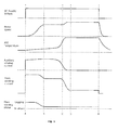
- Figure 1 shows the typical behaviour of a motor with Auxiliary winding controlled by a PTC.
- the PTC is stationary, the PTC is cold and power is applied to the Main winding and to the Auxiliary winding via the PTC.
- the motor accelerates until it reaches a substantially constant speed by time "B". As the motor reaches this speed, there is a corresponding reduction of current in the Main winding.
- the Auxiliary winding current is still flowing, possibly at a slightly higher level because PTCs often exhibit a lower resistance at intermediate temperatures compared to low temperatures. It is normal for the system to be designed so the PTC does not reduce the Auxiliary current until significantly later than the time when the motor is running.
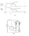
- a system is shown in Figure 4 that implements this method of early disconnection of Auxiliary winding current.
- AC Power source 1 mains supply, for example
- This switch is used to turn the motor on and off; an example is a thermostat in a refrigerator where the motor operates the compressor to provide the cooling.
- Motor 3 is provided with a Main and an Auxiliary winding, the Main winding being powered from the power source while switch 2 is closed.
- Auxiliary winding 5 is powered from the source via switch 7 and resistance 6. The latter is included to improve starting, as previously described, and could be a fixed resistor or a PTC.
- Switch 7 can be any suitable switch such as a triac, electromagnetic relay or combination of devices such as power MOSFETs or IGBTs.
- Control circuit 8 accepts a signal 10 from a current sensor 9 associated with the Main winding. Circuit 8 processes the signal and provides a control signal 11 to close or open switch 7. Optionally, control circuit 8 may accept a signal or power from the power source 1 before or after (as shown) switch 2.
- Circuit 8 is arranged to:
- a preferable method to do this is to estimate motor current during a short period after power is initially applied to the motor. The period is chosen to be shorter than any normal time taken to start the motor and variations in current in this period can be monitored.
- a preferable method is to use an "exponential decay average" calculation.
- an average value is updated when a new sample of motor current is taken and new average is calculated as (1-X)*average + X*Sample, where X is a small fraction. Higher values of X causes faster response to changing currents.
- This average is then used to detect the fall of motor current that results from starting of the motor.
- the motor is deduced to have started.
- a method to do this is to compare new samples of motor current to the average and if the motor current is lower than the average by a margin (expressed as a fraction of the average) then starting is detected. For improved reliability it is preferable to avoid false detection of starting in a case when only a small number of motor current sample values are low. Conveniently this can be done by using a counter that is incremented whenever a sample is determined to be sufficiently low in value. If any motor current sample is above the threshold then the counter is reset to zero. Reliable starting can then be determined when the count exceeds a preset value. This method has the additional benefit of introducing a small delay from the point when the motor current falls below the threshold when starting is actually determined. This delay is useful to ensure proper starting of the motor.
- FIG. 1 shows both the typical motor current profile and the way that the phase of the current varies during the starting process. Initially, when the motor is stationary or running slowly, current in the main winding is typically lagging (inductive). As the motor speed increases the phase of the current moves towards the in-phase condition.
- the phase of the current is aligned with the timing of the bursts a maximum value is obtained and if the phase of the current changes so it is no longer aligned with the burst then the calculated value reduces.
- the bursts are synchronised with a lagging phase so the calculated value reduces either if the phase advances or if the current amplitude reduces.
- Typical motor starting characteristics cause both reduction in the magnitude of the current and advancing of the phase of the current so both of these contribute to reduction in the calculated value.
- This calculated value of current is then used as described previously to determine an average and to detect when motor current has reduced below a threshold calculated from the average.
- the circuit 8 may monitor the current in the main winding (via signal 10) during running of the motor.
- the level of this current is indicative of the loading of the motor, a high current indicates high load.
- a transient motor load it can be an advantage to provide extra power to the motor to overcome this transient load. This can be preferable to using a larger motor because a smaller motor is typically lower cost and can have lower energy consumption during the majority of running conditions at lower load. If the load on the motor is excessive it may stall, which is inconvenient and may also cause overheating. To improve resistance to stalling in induction motors like these it is possible to re-energise the auxiliary winding for a short time.
- Circuit 8 can detect conditions of high load via the current monitor (signal 10) and if it rises sufficiently can close switch 7 for a period to boost power to the motor.
- Optional methods to detect such transient loads include:
- the switch 7 can be maintained closed for the duration that the condition persists.
- a reference motor current may be measured immediately after the switch is closed because energising the switch may alter the current taken by the motor. Motor current is then monitored and if it falls below a preset fraction of the reference value then the high-load condition is determined to have finished and the switch can be opened.
- the switch can be held in the closed condition for a maximum of a preset period. The period is chosen to be sufficient to overcome likely high-load conditions but not so long as to cause overheating of the motor.
- the boost function may be beneficial to use for an extended period and not only to overcome a short term transient condition.
- the motor is subject to a high mechanical load (in the context refrigerators this can be caused by a hot item inside the refrigerator, which takes time to cool down) then it is preferable that the boost function is continued for as long as the higher load condition persists.
- the limitation is normally overheating of the motor windings. Another condition could be when the mains supply voltage is low.
- the motor torque will be reduced and the boost function may be useful to overcome normal operating mechanical load. Heating of the motor may also be reduced in conditions of lower mains supply voltage (because reduction of iron loss) so it may be possible to operate in a boost mode for an extended period.
- boost function If a high load condition persists for a long time then it may be desirable to stop the boost function (and stop the motor if the reduced motor output power is insufficient to operate the load). Overheating of the motor windings is normally the limiting factor to the degree and length of time for which the boost function may be employed. A system using the boost function preferably also has some method to avoid this overheating. A simple method is to allow the boost function to continue only for a maximum preset time however this will have to be set cautiously to avoid unsafe overheating conditions. Consequently the benefit of the boost function will be reduced. Preferably one or more systems included to allow the boost function to continue for longer periods when there is less risk of overheating of the motor. Techniques to achieve this include:
- Power consumption of the system can be reduced by increasing the motor efficiency, but this is limited by the constraints of size, cost and the desire to produce sufficient output power for worst-case load conditions.
- a further alternative strategy is to design the motor for optimum efficiency under typical (low torque/power) operating conditions and to provide additional features or controls to allow the motor output power to be boosted for worst-case conditions. Since the worst-case conditions happen infrequently, reduced efficiency under these conditions is not so critical. Worst-case conditions can include not only high motor load but also adverse operating conditions such as high motor temperature or low mains supply voltage. Since these conditions can persist for an extended time it is desirable for the "boost" function to operate for longer than just a short transient event. To manage normal and boost operating modes it will be necessary to have a control system capable of distinguishing low and high demand on the motor and protecting against adverse behaviour, for example motor overheating.
- the boost function can be used with motors designed only for conventional operation and no boost function. These motors typically use resistance starting and running with power provided to only a main winding, but sometimes low power is applied to an auxiliary winding via a "run capacitor" this could, for example, be connected between the bottom ends of the main and auxiliary windings in Figure 4 .
- a simple application of the boost function to such motors is to reapply high power to the auxiliary winding, for example by closing switch 7 ( Figure 4 ). In this case power is applied to the winding via impedance 6, usually a PTC which has a resistive characteristic.
- Such motors are normally designed to work with a particular PTC to give adequate starting characteristics.
- Impedance 14 (which is optional) and switch 15 control boost current to the auxiliary winding.
- Impedance 14 can be resistive or, preferably, capacitive as this would boost torque at higher motor speeds.
- Some conventional motors are used with a run capacitor connected to provide phase-advanced current to the auxiliary winding during normal running. These provide a lower level of current in the auxiliary winding; to effectively boost operation capacitive impedance 14 may provide a higher level of capacitive current.
- motors are designed to make optimum use of a boost function and there are several options of how this boost function can be configured with a new design of motor.
- Option Figure reference Motor features Operating method 1 10 Compared to a conventional motor (i.e. no boost function), the auxiliary winding has a lower resistance and higher inductance.
- boost current is provided via impedance 14 and switch 15.
- the reduced resistance of the auxiliary winding allows boost operation for extended periods without excessive heating of the winding.
- impedance 14 is capacitive so that there is a large phase angle difference between the current in the main winding and the current in the auxiliary winding.
- the main winding is designed for optimum efficiency when it is operated from phase-switched AC mains supply voltage as shown in Figure 12 but can operate with higher, or full, AC mains supply under conditions of high duty.
- Switch 17 ( Figure 11 ) controls power to the main winding. It is turned on synchronously with the mains supply voltage but with a time delay as shown in Figure 12 . Turn off of the switch can be coincidental with a zero crossing of the supply voltage or with zero current in the winding (typically in the case of a triac being used as the switch). The effect is to apply a lower RMS voltage to the winding. When the motor is operating below maximum load the reduced RMS voltage is sufficient to provide the required power but power losses are reduced because of the lower magnetic flux and current in the motor.
- Switch 17 is operated at a higher duty or continuously to provide a higher or maximum voltage to the main winding.
- Switch 7 provides current to the auxiliary winding to start the motor, for example by resistive starting.
- Switch 17 can be operated with a small time delay during starting to improve the phase difference between main and auxiliary current.
- Motor 3 is provided with two windings W1 and W2, either of which can be used to run the motor.
- One winding (W1, for example) applies a higher flux to the rotor so that high torque can be sustained when the motor loading is high.
- the other winding (W2) applies a lower flux to the rotor to give sufficient flux for lower load conditions.
- W1 is optimised to give the maximum required torque
- W2 is optimised for maximum efficiency under conditions of reduced torque and.
- Switch 7 or switch 17 is closed to energise one or other of the windings. Under conditions of reduced load the winding optimised to those conditions is energised whereas if the motor load is high the other winding is energised.
- an impedance can be inserted in series with one of the windings to increase the phase difference between the currents. This may be disadvantageous to the running conditions so a further alternative is to provide an additional switched current path to one winding, for example as illustrated in Figure 10 .
- Main winding 4 of the motor is provided with a connection 24 to a tapping point.
- the winding and tapping point are designed so a high flux is provided to the rotor if the AC mains supply is applied across the tapping point 24 to the common point 25, and a lower flux is generated if the supply voltage is applied to the full main winding.
- the windings and levels of flux are designed for maximum efficiency at a lower load when the full winding is energised or higher torque output, but lower efficiency, when part of the winding is energised. Power is applied to the full winding via switch 23 or part of the main winding by switch 21 according to the level of load on the motor.
- Circuit 8 controls the various switches in the system to start, run and boost the motor. Control of these modes and switching between the modes should be done in accordance with conditions of the motor. These are monitored and communicated to circuit 8. Motor current is an important parameter and Figure 14 shows a sensing device 9 communicating a signal 10 representative of current parameter or parameters (e.g. AC or RMS amplitude, instantaneous amplitude, phase shift relative to reference or wave shape) to control circuit 8.
- current parameter or parameters e.g. AC or RMS amplitude, instantaneous amplitude, phase shift relative to reference or wave shape
- Other characteristic parameters that may be used by circuit 8 to control the system include supply voltage (12) and motor temperature which can be detected by a conventional sensor (e.g. thermistor, thermocouple, semiconductor junction etc.) in proximity to the motor (not shown).
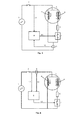
- Optional locations for the current sensor 9 are shown in Figures 5 and 6 .
- the sensor monitors the sum of Main plus Auxiliary currents.
- auxiliary current typically there is only a moderate change of auxiliary current during the starting process, so the fall of main winding current can still be detected reliably but a different fraction should be used for the threshold fraction that is used to trigger disconnection of the auxiliary current.
- OLP overload protector
- an electromechanical OLP is used to protect such motors from overheating during stall or overload conditions, such as described in US2768342 .
- Included in these devices are an electrical resistance heater and this resistance can be used to sense the current flowing through the device. Typically they are inserted in the power supply to the motor and carry both the Main and Auxiliary currents. The voltage across the resistance can be used as the signal 10 to monitor motor current. This is advantageous in two ways:
- a current sensor associated with the circuit supplying only the Main winding is preferable to use.
- a low-cost method is to insert a resistance in this circuit and monitor the voltage across the resistance.
- the resistance should have a low value, preferably less than 1 ohm and more preferably less than 0.1 ohm. This gives only a small voltage to detect and this may require amplification before processing to detect fall of current.
- An economical method to provide such a resistance is to use a length of copper track included in the printed circuit board (PCB) that is also used in the construction of the system.
- PCB printed circuit board
- an alternative method can be used to determine the necessary time for which switch 7 has to be closed to start the motor.
- One method is to analyse motor currents and/or voltages after the starting process to determine (calculate) how efficiently the motor started then adjust the timing for switch 7 in subsequent starting processes to reduce the energy consumption.
- control circuit uses an on-time for the switch which varies in response to the result from the previous starting process.
- continuous power is applied to the control circuit to maintain a volatile memory or the control circuit must include some other store (such as non-volatile memory, or an analog voltage on a capacitor).
- the control circuit uses an on-time for the switch 7 that depends on the result of the previous starting process, or a default value where it is the first starting event.
- the control circuit e.g. successful/unsuccessful, or quality of start characterised by rate of rise/fall of motor currents or voltages
- information is stored to allow adjustment of the time used for the next starting process.
- the running of the motor is controlled so the cooling provides a desired temperature or time-dependent temperature profile in a particular zone.
- An electronic temperature sensor located in the zone can be used together with a threshold circuit to start the motor when the temperature rises above a first threshold temperature and stop the motor when the temperature falls below a second threshold temperature.
- these are used with separate motor controls, the separation being a result of the distance between the zone and the motor or because the technology of the threshold circuit (electronic) is different from that of the motor control (PTC and bimetallic OLP).
- the motor control is electronic then the temperature control function can be integrated into a single electronic system with the motor control function to minimise the size, cost, complexity and energy consumption associated with the overall control functions.
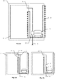
- Figure 15a illustrates a self-contained refrigeration appliance 30 inside which is a zone 31 that is refrigerated by a motorcompressor 32 and gas circuit 33. Temperature sensor 34 is located in the zone 31 and sends a signal to control 35 located on the motorcompressor. Mains power to operate the appliance connects via supply cable 36 to the control.
- Figures 15b and 15c show other arrangements where, respectively, the control 35 is located in the zone 31 or elsewhere in the appliance.
- cable 37 connects power from the control to the motorcompressor and optionally carries other signals such as a characteristic temperature of the motorcompressor back to the control 35.
- thermocouple voltage A variety of technologies can be used for temperature sensor 34 including, but not limited to: thermistor resistance, semiconductor junction voltage, resistance change of a metallic or non-metallic conductor and thermocouple voltage.
- the method should at least respond to a sensed temperature and a motor current.
- the motor current is indicative of rate of electrical energy consumption.
- True power consumption can be evaluated in the optimisation method by combining the current and the motor voltage using techniques known to those skilled in the art.
- An estimate of total (average) electrical energy consumption can be made from integrating either the current or the power.
- Ton Tcycle k .
- Demand with a limit to minimum Ton as described previously.
- proportional running time should relate to thermal demand if temperature is to be stabilised.
- Tcycle can be optimised to achieve minimum energy consumption.
- search algorithms to find optimum (min/max) conditions are known and generally involve a repetitive process in which small disturbances are imposed on the controlled variable (Tcycle), and the response (increase or decrease of energy consumption) is measured. Then the nominal value of the controlled variable is changed accordingly to move nearer to an optimum condition.
- Actual energy consumption can be calculated by the control from measurements of motor current and voltage, taking into account phase differences and waveform distortion as appropriate. A simple way to do this is to sample voltage and current at a number of times during each mains cycle, and derive digital representations of the values (for example using analog and analog to digital conversion techniques). Power consumption is then estimated by multiplying current and voltage samples in a digital circuit. An estimate of total energy consumption can then be calculated by summing the estimates of power consumption. This summation should preferably run for a period which includes at least a full Ton period, so that it represents energy to start as well as run the motor.
- a common requirement for induction motors and, in particular, refrigeration motorcompressor is a device to prevent overheating of the motor windings due to overloading.
- Techniques include bimetallic switch and electronic overload protectors as explained above. The former are generally lower cost than the latter but the latter have advantages, in particular the ability to use a single design across a range of different motorcompressor.
- the overload protection function is particularly advantageous to maximise the boost amount and duration while avoiding overheating of the motor windings.
- the overload protection method should preferably take account of the activation of the boost function because the electrical conditions would change simply because of this activation, and different processing and limits would apply to avoid overheating.
- both main and auxiliary/Starting/boosting windings When both main and auxiliary/Starting/boosting windings are activated, current may be sensed in both windings and used to detect risk of overheating. For example, in resistance-start configurations, the impedance of the auxiliary winding is affected less by EMF induced from motor operation and more by the electrical resistance of the winding. This can be used with knowledge of the temperature coefficient of resistance to estimate auxiliary winding temperature, which is indicative also of the main winding temperature.
- a single design of overload protection device that can be applied to a range of motorcompressors is a particular advantage to manufacturers of refrigeration motorcompressors and refrigerators as it reduces or eliminates the need to stock multiple types of overload protector for each of the various motorcompressors that are used. However this benefit may not be sufficient to justify the additional cost of the electronic alternative. If the benefit can be provided at lower incremental cost then it is very desirable.
- Systems for electronic overload protection which also include a basic motor starting function, are described in EP1494346 and generally employ:
- control device which implements measurement and control functions associated with monitoring and protecting the motor windings.
- these functions can be added at very low additional cost, particularly if the control system is embodied substantially as an integrated circuit, and more preferably if digital circuits are used in the implementation of the control methods and yet more preferably if the integrated circuit is, or includes, a microcontroller.
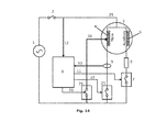
- Figure 18 illustrates a system that includes both optimised starting and electronic overload protection functions. It is similar to the system shown in Figure 11 , with like reference numerals indicating like features, but has an additional temperature sensor 39 which provides a signal representative of a motor temperature to control circuit 8.
- Current sensor 9 (which may be embodied in a variety of ways and in alternative locations in the circuit, as described previously) provides a signal representing a motor current to the control circuit.
- Signal 12 also provided to the control circuit, represents the mains supply voltage.
- thermostat function In consideration of integrating a thermostat function with a starting device as described previously, again few additional components are required even if the thermostat function also includes optimisation of energy consumption by methods described above.
- An integrated system is illustrated in Figure 19 , like references having like functions as Figures 11 and 18 . The differences are:
- the control circuit senses the motor current by signal 10 and controls starting, running and stopping of the motor via signals to switches 17 and 18. This gives the control circuit all necessary information and motor control means necessary to implement the temperature control methods described above, optionally with optimisation of operating cycle and timing to minimise energy consumption.
- the preset target temperature held in the control circuit may be adjusted by the user via the control 43.
- thermostat functions can be added at very low additional cost, particularly if the control system is embodied substantially as an integrated circuit, and more preferably if digital circuits are used in the implementation of the control methods and yet more preferably if the integrated circuit is, or includes, a microcontroller.
- Figure 20 illustrates a system that integrates all of an optimised starting device, an electronic overload protector and a thermostat (with optional energy optimisation and user control of target temperature). It can be seen that great functionality is achieved with few components so very good user and manufacturing benefits can be provided at low manufactured cost.
- control circuit 8 may be constructed in a variety of ways, including:
- control circuit In order to maximise energy efficiency of the overall system, the control circuit should be arranged to have low power consumption during continuous running of the compressor. Provided that the "boost" option is not included, it is possible for the circuit to enter a low power, quiescent state after the auxiliary switch has been turned off. For example, if a microcontroller is used in the circuit it can be put into a state commonly called “sleep" where power consumption is very low.
- low power circuits to implement the control function operate from low voltage DC and the means of provision of this power is important to the overall power consumption of the system.
- One low-cost method is to use a capacitor to derive an AC current from the AC power source, then to rectify and voltage-limit the resulting DC. However this technique consumes about the same power whether or not DC current is taken by the supplied circuits.
- An alternative is to rectify the AC supply to give high voltage DC then use a transistor as a series regulator to give a low voltage DC supply. This arrangement is very inefficient when DC power is taken, but has very low power consumption if no DC power is drawn.
- the inefficiency may be acceptable as it applies only for the short starting time and the extra power taken during this period is still a small amount in comparison to the motor power consumption at this time.
- another alternative is to rectify (optionally with diode-capacitor voltage multiplication) the voltage across the resistance and use this to power the low voltage circuits. This is low cost because few additional components are required and is effective because the additional power consumption is very small.
- a motor starting device for an AC induction motor having a main winding and an auxiliary winding comprising a control circuit, a resistive element and a switch wherein the resistive element, the switch and the auxiliary winding are connected in series with a power source and wherein: the starting device controls the power to the auxiliary winding during a motor starting process; and the control circuit controls the opening and closing of the switch; and the switch is closed to start the motor; and the switch is opened after the motor has started; and the circuit is responsive to a characteristic signal representative of a current or voltage of the motor.
- the device includes one or both of an electronic overload protection circuit and a thermostat input for motor control, in particular as described above/later.
- the said characteristic signal represents a motor current and the control circuit causes the switch to open when a subsequent amplitude of the signal is smaller than a preset fraction of an initial amplitude of the signal.
- the motor current comprises the main winding current.
- the motor current is the main winding current.
- the control circuit controls the on-time for which the switch is closed and the on-time used in one motor starting process is determined by a said characteristic signal in a previous motor starting process.
- the said characteristic signal is a motor current subsequent to opening of the switch and where the on-time used in a subsequent starting process is reduced when the signal amplitude is below a threshold or reduces at a rate faster than a threshold rate.
- the said characteristic signal is a motor voltage subsequent to opening of the switch and where the on-time used in a subsequent starting process is reduced when the signal amplitude is above a threshold or increases at a rate faster than a threshold rate.
- a motor starting device for an AC induction motor having a main winding and an auxiliary winding comprising a control circuit and a switch wherein the switch and the auxiliary winding are connected in series with a power source wherein: the starting device controls the power to the auxiliary winding during motor running; and the control circuit controls the opening and closing of the switch and the switch is closed to increase the power to the motor; and the circuit is responsive to a characteristic signal representative of a current of the motor.
- the switch is maintained in a closed condition while the signal is above a fraction of a reference value and the reference value is representative of the motor current at an earlier time.
- the switch is maintained in a closed condition for a preset maximum period.
- control device for an AC induction motor comprising two or more windings wherein the control device comprises a switch to control power applied to at least one winding and wherein: the control device is responsive to current in a motor winding; and the control device determines conditions of higher and lower mechanical motor load; and the control device operates a switch to increase power to the motor under conditions of higher motor load and reduces power to the motor under conditions of lower motor load.
- the switch is operated synchronously with an AC supply voltage so the RMS amplitude of a voltage applied via the switch to a motor winding is lower than that of the AC supply.
- the switch is controlled to open and close synchronously with an AC supply voltage to apply a voltage to a winding of phase delayed relative to the AC supply.
- the switch is operated to connect a winding of the motor to an AC supply voltage substantially continuously for more than one complete cycle of the supply voltage.
- the said connection to the AC supply voltage includes a series impedance.
- a motor system comprising an AC induction motor comprising two or more windings and a control device as above wherein: the system is operable in a condition of higher mechanical output power and a condition of lower mechanical output power; and the control device is responsive to the mechanical load on the motor; and the control device applies higher electrical power to the motor in a condition of higher mechanical load and lower electrical power in a condition of lower mechanical load.
- control device applies power to one winding of the motor in a condition of lower mechanical load and applies power to more than one winding in a condition of higher mechanical load.
- control device applies power to one winding of the motor only in a condition of lower mechanical load and only to another winding in a condition of higher mechanical load.
- control device applies power only to a part or whole of a winding in a condition of lower mechanical load and only to a different part or whole of a winding in a condition of higher mechanical load.
Landscapes
- Engineering & Computer Science (AREA)
- Power Engineering (AREA)
- Physics & Mathematics (AREA)
- Mechanical Engineering (AREA)
- Thermal Sciences (AREA)
- General Engineering & Computer Science (AREA)
- Control Of Ac Motors In General (AREA)
- Control Of Positive-Displacement Pumps (AREA)
Priority Applications (1)
| Application Number | Priority Date | Filing Date | Title |
|---|---|---|---|
| EP18199723.0A EP3447896B1 (de) | 2010-11-30 | 2011-11-23 | Motorsteuerungssysteme |
Applications Claiming Priority (1)
| Application Number | Priority Date | Filing Date | Title |
|---|---|---|---|
| GBGB1020258.8A GB201020258D0 (en) | 2010-11-30 | 2010-11-30 | Motor control systems |
Related Child Applications (1)
| Application Number | Title | Priority Date | Filing Date |
|---|---|---|---|
| EP18199723.0A Division EP3447896B1 (de) | 2010-11-30 | 2011-11-23 | Motorsteuerungssysteme |
Publications (2)
| Publication Number | Publication Date |
|---|---|
| EP2458728A2 true EP2458728A2 (de) | 2012-05-30 |
| EP2458728A3 EP2458728A3 (de) | 2018-04-11 |
Family
ID=43500841
Family Applications (2)
| Application Number | Title | Priority Date | Filing Date |
|---|---|---|---|
| EP11190327.4A Withdrawn EP2458728A3 (de) | 2010-11-30 | 2011-11-23 | Motorsteuerungssysteme |
| EP18199723.0A Active EP3447896B1 (de) | 2010-11-30 | 2011-11-23 | Motorsteuerungssysteme |
Family Applications After (1)
| Application Number | Title | Priority Date | Filing Date |
|---|---|---|---|
| EP18199723.0A Active EP3447896B1 (de) | 2010-11-30 | 2011-11-23 | Motorsteuerungssysteme |
Country Status (2)
| Country | Link |
|---|---|
| EP (2) | EP2458728A3 (de) |
| GB (1) | GB201020258D0 (de) |
Cited By (14)
| Publication number | Priority date | Publication date | Assignee | Title |
|---|---|---|---|---|
| CN102612310A (zh) * | 2012-04-05 | 2012-07-25 | 杭州星帅尔电器股份有限公司 | 微型组合式起动热保护装置的制作和装配方法 |
| WO2015024009A3 (en) * | 2013-08-16 | 2015-06-04 | Tecumseh Products Company, Inc. | Method and apparatus to control a single-phase induction motor |
| EP2787630A3 (de) * | 2013-04-04 | 2016-05-18 | Hamilton Sundstrand Corporation | Erkennung von Fehlern in Motoren und Antrieben |
| WO2016111768A1 (en) * | 2015-01-09 | 2016-07-14 | V Square/R Llc | Dynamic power control for induction motors |
| US9425728B2 (en) | 2013-06-12 | 2016-08-23 | V Square/R Llc | Dynamic power control for induction motors |
| CN106357163A (zh) * | 2016-11-17 | 2017-01-25 | 常熟市天银机电股份有限公司 | 商用制冷压缩机电机的起动装置 |
| CN106374783A (zh) * | 2016-11-17 | 2017-02-01 | 常熟市天银机电股份有限公司 | 商用制冷压缩机电机互感式无触点电流起动器 |
| CN106385204A (zh) * | 2016-11-17 | 2017-02-08 | 常熟市天银机电股份有限公司 | 制冷压缩机无功耗起动保护器 |
| CN107888123A (zh) * | 2017-12-26 | 2018-04-06 | 杭州恒业电机制造有限公司 | 一种单相电机控制电路 |
| CN108679891A (zh) * | 2018-07-24 | 2018-10-19 | 杭州星帅尔电器股份有限公司 | 家用制冷机的控制系统及其控制方法 |
| CN109039163A (zh) * | 2018-08-03 | 2018-12-18 | 东莞市杰美电器有限公司 | 带遥控功能的电机控制系统及电机驱动装置 |
| US11073319B2 (en) | 2017-12-29 | 2021-07-27 | Johnson Controls Technology Company | Capacity control technique with motor temperature override |
| DE102021109842A1 (de) | 2021-04-19 | 2022-10-20 | Vaillant Gmbh | Verfahren zum Betreiben eines Verdichters eines Wärmepumpenkreislaufes |
| EP4246797A1 (de) * | 2022-03-16 | 2023-09-20 | B.D.G. el S.r.l. | Steuerung für kühlkompressoren und ein steuerungsverfahren für eine solche steuerung |
Families Citing this family (1)
| Publication number | Priority date | Publication date | Assignee | Title |
|---|---|---|---|---|
| US10985550B1 (en) * | 2019-10-16 | 2021-04-20 | Schneider Electric USA, Inc. | Progressive protection functions for motor overload relay |
Citations (3)
| Publication number | Priority date | Publication date | Assignee | Title |
|---|---|---|---|---|
| US2768342A (en) | 1953-03-09 | 1956-10-23 | Metals & Controls Corp | Motor protective switch |
| EP0820621A1 (de) | 1995-04-11 | 1998-01-28 | The Wingard Company, Inc. | Anti-diebstahlvorrichtung zur überwachung von elektronischem gerät |
| EP1494346A2 (de) | 2003-07-04 | 2005-01-05 | B.D.G. El. S.P.A. | Steuerungsgerät, insbesondere für einen Asynchronmotor und mehr insbesondere für Kompressoren von kältetechnischen Apparaten |
Family Cites Families (7)
| Publication number | Priority date | Publication date | Assignee | Title |
|---|---|---|---|---|
| DE3219199C2 (de) * | 1982-05-21 | 1987-04-16 | Hartmann & Braun Ag, 6000 Frankfurt | Schaltungsanordnung zur Überwachung der Erwärmung von elektrisch betriebenen Motoren |
| US4658195A (en) * | 1985-05-21 | 1987-04-14 | Pt Components, Inc. | Motor control circuit with automatic restart of cut-in |
| BR8906225A (pt) * | 1989-11-28 | 1991-06-04 | Brasil Compressores Sa | Circuito eletronico para partida de motor a inducao monofasico |
| US5808441A (en) * | 1996-06-10 | 1998-09-15 | Tecumseh Products Company | Microprocessor based motor control system with phase difference detection |
| US6034503A (en) * | 1997-06-17 | 2000-03-07 | Pertessis; John | Method and apparatus for starting motors |
| DE10062940B4 (de) * | 2000-12-16 | 2012-09-20 | Ebm-Papst Mulfingen Gmbh & Co. Kg | Verfahren und Steuersystem zur elektronischen Drehzahlsteuerung eines Asynchronmotors |
| KR100422329B1 (ko) * | 2001-11-27 | 2004-03-11 | 김인석 | 단상유도 전동기 기동용 전압식 전자 릴레이 |
-
2010
- 2010-11-30 GB GBGB1020258.8A patent/GB201020258D0/en not_active Ceased
-
2011
- 2011-11-23 EP EP11190327.4A patent/EP2458728A3/de not_active Withdrawn
- 2011-11-23 EP EP18199723.0A patent/EP3447896B1/de active Active
Patent Citations (3)
| Publication number | Priority date | Publication date | Assignee | Title |
|---|---|---|---|---|
| US2768342A (en) | 1953-03-09 | 1956-10-23 | Metals & Controls Corp | Motor protective switch |
| EP0820621A1 (de) | 1995-04-11 | 1998-01-28 | The Wingard Company, Inc. | Anti-diebstahlvorrichtung zur überwachung von elektronischem gerät |
| EP1494346A2 (de) | 2003-07-04 | 2005-01-05 | B.D.G. El. S.P.A. | Steuerungsgerät, insbesondere für einen Asynchronmotor und mehr insbesondere für Kompressoren von kältetechnischen Apparaten |
Cited By (16)
| Publication number | Priority date | Publication date | Assignee | Title |
|---|---|---|---|---|
| CN102612310A (zh) * | 2012-04-05 | 2012-07-25 | 杭州星帅尔电器股份有限公司 | 微型组合式起动热保护装置的制作和装配方法 |
| EP2787630A3 (de) * | 2013-04-04 | 2016-05-18 | Hamilton Sundstrand Corporation | Erkennung von Fehlern in Motoren und Antrieben |
| US10060982B2 (en) | 2013-04-04 | 2018-08-28 | Hamilton Sundstrand Corporation | Detecting faults in motors and drives |
| US9425728B2 (en) | 2013-06-12 | 2016-08-23 | V Square/R Llc | Dynamic power control for induction motors |
| WO2015024009A3 (en) * | 2013-08-16 | 2015-06-04 | Tecumseh Products Company, Inc. | Method and apparatus to control a single-phase induction motor |
| WO2016111768A1 (en) * | 2015-01-09 | 2016-07-14 | V Square/R Llc | Dynamic power control for induction motors |
| CN106374783B (zh) * | 2016-11-17 | 2018-12-04 | 常熟市天银机电股份有限公司 | 商用制冷压缩机电机互感式无触点电流起动器 |
| CN106357163A (zh) * | 2016-11-17 | 2017-01-25 | 常熟市天银机电股份有限公司 | 商用制冷压缩机电机的起动装置 |
| CN106374783A (zh) * | 2016-11-17 | 2017-02-01 | 常熟市天银机电股份有限公司 | 商用制冷压缩机电机互感式无触点电流起动器 |
| CN106385204A (zh) * | 2016-11-17 | 2017-02-08 | 常熟市天银机电股份有限公司 | 制冷压缩机无功耗起动保护器 |
| CN107888123A (zh) * | 2017-12-26 | 2018-04-06 | 杭州恒业电机制造有限公司 | 一种单相电机控制电路 |
| US11073319B2 (en) | 2017-12-29 | 2021-07-27 | Johnson Controls Technology Company | Capacity control technique with motor temperature override |
| CN108679891A (zh) * | 2018-07-24 | 2018-10-19 | 杭州星帅尔电器股份有限公司 | 家用制冷机的控制系统及其控制方法 |
| CN109039163A (zh) * | 2018-08-03 | 2018-12-18 | 东莞市杰美电器有限公司 | 带遥控功能的电机控制系统及电机驱动装置 |
| DE102021109842A1 (de) | 2021-04-19 | 2022-10-20 | Vaillant Gmbh | Verfahren zum Betreiben eines Verdichters eines Wärmepumpenkreislaufes |
| EP4246797A1 (de) * | 2022-03-16 | 2023-09-20 | B.D.G. el S.r.l. | Steuerung für kühlkompressoren und ein steuerungsverfahren für eine solche steuerung |
Also Published As
| Publication number | Publication date |
|---|---|
| EP2458728A3 (de) | 2018-04-11 |
| GB201020258D0 (en) | 2011-01-12 |
| EP3447896B1 (de) | 2020-08-12 |
| EP3447896A1 (de) | 2019-02-27 |
Similar Documents
| Publication | Publication Date | Title |
|---|---|---|
| EP3447896B1 (de) | Motorsteuerungssysteme | |
| CA2680529C (en) | Open-loop method for controlling power | |
| DK174114B1 (da) | Fremgangsmåde til hastighedsregulering af en kompressor samt styring, der gør brug af fremgangsmåden | |
| EP2201437B1 (de) | Verdichter mit einem system und einem verfahren zur leistungsfaktorkorrektur | |
| EP2140213B1 (de) | Kühlschrank und betriebsverfahren dafür | |
| US5534760A (en) | Compressor control circuit | |
| JP2003286964A (ja) | 線形圧縮機の運転制御装置及びその方法 | |
| US7471058B2 (en) | Starting device and starting method for a single-phase induction motor | |
| JP5378630B1 (ja) | 電動圧縮機の制御方法、制御装置、及び冷蔵庫 | |
| WO2010133513A1 (en) | Arrangement for starting a single phase induction motor | |
| EP2140215B1 (de) | Kühlschrank und betriebsverfahren dafür | |
| CN101663811B (zh) | 用于控制功率的开环方法 | |
| EP2256920A2 (de) | Motorsteuerungssysteme | |
| EP3312425B1 (de) | System und verfahren zur zuführung und steuerung eines verdichters mit variabler kapazität und kühler mit einem verdichter mit variabler kapazität | |
| EP1990591A1 (de) | Unabhängige Universalvorrichtung zur Steuerung der Drehzahl eines motorbetriebenen Kompressors von Haushaltskühlgeräten und Steuerverfahren dafür | |
| GB2512129A (en) | Force-cooled air-conditioning system | |
| MXPA99003174A (en) | Method for speed control of compressor and control arrangement using the method | |
| JP2002221383A (ja) | 温蔵庫のヒータ制御装置 |
Legal Events
| Date | Code | Title | Description |
|---|---|---|---|
| PUAI | Public reference made under article 153(3) epc to a published international application that has entered the european phase |
Free format text: ORIGINAL CODE: 0009012 |
|
| AK | Designated contracting states |
Kind code of ref document: A2 Designated state(s): AL AT BE BG CH CY CZ DE DK EE ES FI FR GB GR HR HU IE IS IT LI LT LU LV MC MK MT NL NO PL PT RO RS SE SI SK SM TR |
|
| AX | Request for extension of the european patent |
Extension state: BA ME |
|
| RIC1 | Information provided on ipc code assigned before grant |
Ipc: H02P 1/02 20060101ALI20171129BHEP Ipc: H02P 1/44 20060101ALI20171129BHEP Ipc: H02P 1/42 20060101AFI20171129BHEP |
|
| PUAL | Search report despatched |
Free format text: ORIGINAL CODE: 0009013 |
|
| AK | Designated contracting states |
Kind code of ref document: A3 Designated state(s): AL AT BE BG CH CY CZ DE DK EE ES FI FR GB GR HR HU IE IS IT LI LT LU LV MC MK MT NL NO PL PT RO RS SE SI SK SM TR |
|
| AX | Request for extension of the european patent |
Extension state: BA ME |
|
| RIC1 | Information provided on ipc code assigned before grant |
Ipc: H02P 1/02 20060101ALI20180306BHEP Ipc: H02P 1/44 20060101ALI20180306BHEP Ipc: H02P 1/42 20060101AFI20180306BHEP |
|
| STAA | Information on the status of an ep patent application or granted ep patent |
Free format text: STATUS: THE APPLICATION IS DEEMED TO BE WITHDRAWN |
|
| 18D | Application deemed to be withdrawn |
Effective date: 20181012 |