EP1494898B1 - Sicherheitsgurtaufroller - Google Patents
Sicherheitsgurtaufroller Download PDFInfo
- Publication number
- EP1494898B1 EP1494898B1 EP02789396A EP02789396A EP1494898B1 EP 1494898 B1 EP1494898 B1 EP 1494898B1 EP 02789396 A EP02789396 A EP 02789396A EP 02789396 A EP02789396 A EP 02789396A EP 1494898 B1 EP1494898 B1 EP 1494898B1
- Authority
- EP
- European Patent Office
- Prior art keywords
- wire
- seat belt
- spool
- belt retractor
- pin
- Prior art date
- Legal status (The legal status is an assumption and is not a legal conclusion. Google has not performed a legal analysis and makes no representation as to the accuracy of the status listed.)
- Expired - Lifetime
Links
- 230000000670 limiting effect Effects 0.000 claims description 50
- 239000000203 mixture Substances 0.000 claims description 2
- 230000007246 mechanism Effects 0.000 description 9
- 238000004804 winding Methods 0.000 description 6
- 208000027418 Wounds and injury Diseases 0.000 description 5
- 229910000831 Steel Inorganic materials 0.000 description 2
- 230000006378 damage Effects 0.000 description 2
- 238000006073 displacement reaction Methods 0.000 description 2
- 230000000694 effects Effects 0.000 description 2
- 208000014674 injury Diseases 0.000 description 2
- 239000010959 steel Substances 0.000 description 2
- 230000009471 action Effects 0.000 description 1
- 230000008901 benefit Effects 0.000 description 1
- 238000010276 construction Methods 0.000 description 1
- 239000000463 material Substances 0.000 description 1
- 230000004048 modification Effects 0.000 description 1
- 238000012986 modification Methods 0.000 description 1
- 230000004044 response Effects 0.000 description 1
- 230000000452 restraining effect Effects 0.000 description 1
Images


Classifications
-
- B—PERFORMING OPERATIONS; TRANSPORTING
- B60—VEHICLES IN GENERAL
- B60R—VEHICLES, VEHICLE FITTINGS, OR VEHICLE PARTS, NOT OTHERWISE PROVIDED FOR
- B60R22/00—Safety belts or body harnesses in vehicles
- B60R22/34—Belt retractors, e.g. reels
-
- B—PERFORMING OPERATIONS; TRANSPORTING
- B60—VEHICLES IN GENERAL
- B60R—VEHICLES, VEHICLE FITTINGS, OR VEHICLE PARTS, NOT OTHERWISE PROVIDED FOR
- B60R22/00—Safety belts or body harnesses in vehicles
- B60R22/34—Belt retractors, e.g. reels
- B60R22/341—Belt retractors, e.g. reels comprising energy-absorbing means
- B60R22/3413—Belt retractors, e.g. reels comprising energy-absorbing means operating between belt reel and retractor frame
-
- B—PERFORMING OPERATIONS; TRANSPORTING
- B60—VEHICLES IN GENERAL
- B60R—VEHICLES, VEHICLE FITTINGS, OR VEHICLE PARTS, NOT OTHERWISE PROVIDED FOR
- B60R22/00—Safety belts or body harnesses in vehicles
- B60R22/34—Belt retractors, e.g. reels
- B60R22/46—Reels with means to tension the belt in an emergency by forced winding up
-
- B—PERFORMING OPERATIONS; TRANSPORTING
- B60—VEHICLES IN GENERAL
- B60R—VEHICLES, VEHICLE FITTINGS, OR VEHICLE PARTS, NOT OTHERWISE PROVIDED FOR
- B60R22/00—Safety belts or body harnesses in vehicles
- B60R22/28—Safety belts or body harnesses in vehicles incorporating energy-absorbing devices
- B60R2022/286—Safety belts or body harnesses in vehicles incorporating energy-absorbing devices using deformation of material
Definitions
- the present invention relates to a seat belt retractor.
- a seat belt retractor generally comprises a cylindrical bobbin or spool with a circular cross-section.
- Seat belt webbing is attached to and wound around the spool, and the spool is mounted on a spool shaft to be rotatable in the retractor to wind in webbing under the action of a retractor spring and to pay out webbing under the influence of relatively gentle forwardly directed movement of a vehicle occupant, for example to allow for normal movement associated with vehicle occupancy such as reaching forwards to activate a radio or a window, or to reach a glove compartment or door pocket.
- the more extreme momentum of the vehicle occupant activates a crash sensor which locks the spool against rotation and thus prevents forward motion of the vehicle occupant and injury due to the vehicle occupant colliding with the interior structure of the vehicle.
- a torsion bar may be incorporated into the spool.
- a torsion bar is made of steel that twists when high torque is applied and can rotate up to seven or eight times while remaining intact. It is connected to both ends of a split spool. One end of the spool is held against rotation by a locking ring engaged by a load bearing pawl when a crash sensor indicates danger.
- the other end of the spool is prevented from rotating by its connection to the locking ring via the torsion bar, but when the crash forces exceed a predetermined level, the torsion bar will twist and allow a limited controlled further payout of webbing, generally in proportion to the momentum of the vehicle occupant at the moment a crash condition is sensed. This payout lessens the otherwise severe restraining forces on the vehicle occupant at high speeds, especially during the initial moments of a crash.
- a seat belt retractor comprising: a spool, mounted for rotation in the retractor for retraction or payout of seat belt webbing depending upon the rotation direction of the spool; a locking ring attached to one end of the spool; a means for locking the locking ring against rotation when a crash is sensed; and a means for force limiting allowing further payout of the seat belt webbing after the locking ring has locked, under the influence of a vehicle occupant's forward momentum, characterized in that means for force limiting comprises a length of wire, attached at one end to one of the spool or the locking ring, and wound at a distance spaced from said one end, on a pin fixed to the other of the spool or the locking ring, so that under the influence of crash forces above a predetermined value, the wire is pulled around the pin.
- the load limiting arrangement of the present invention can be used in a traditional seat belt retractor that is well known to a person skilled in the art.
- a seat belt retractor is shown in general in Fig. 1 and comprises a cylindrical retractor spool 1 mounted for rotation in a frame 8 to wind in and payout seat belt webbing (not shown).
- a sensor activates a locking mechanism to move a lockbar 10 to engage the teeth of a locking ring 3 fixed to one end of the spool 1, subject to further movement due to load limiting arrangements. This prevents rotation of the spool.
- the other end of the spool 1 is connected to a rewind spring mechanism (not shown) that comprises a clock type coiled spring that biases the spool 1 to a webbing rewound condition.
- a load limiting arrangement according to the present invention comprises a wire 4 that is fitted between the locking ring 3 and the spool 1, for example between the locking ring 3 and a spool spindle 20.
- This may take any one of a variety of embodiments such as that shown in Figs. 2 to 5, or that shown in Figs. 6 to 10 or that shown in Figs. 11 and 13 with the modifications shown in any one of Figs. 13 to 16.
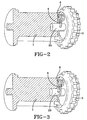
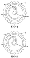
- Figs. 2 to 5 illustrate a first embodiment of the invention in which the wire 4 is attached to the spool spindle 20 by passing through a hole 21 in the spool spindle and is coiled around a pin 6 fixed to the spool side of the locking ring 3.
- the spindle 20 is fixed to the spool 1 and the coils of the wire 4 are arranged to wind spirally along the pin 6.
- the wire is shown in plan view in Fig. 4. In Figs. 3 and 5 the disposition of the wire during load limiting is shown as the wire 4 winds around the spindle 20.
- the wire may be wound around each with a single turn, or a multiple number of turns, or a mixture of single and multiple turns, to tailor the load limiting effect to the required turns, to tailor the load limiting effect to the required level for the intended application.
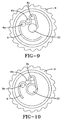
- Figs. 6 to 10 illustrate a second embodiment of the invention comprising a plurality of pins 6a, 6b, 6c, all attached to the locking ring 3.
- the wire 4 is attached to the spool spindle 20 by a bent end 30 of the wire that fits in a hole 31 in the spindle.
- the wire is then bent around each pin 6a, 6b, and 6c.
- This provides a single level load limiter.
- the wire 4 is drawn around all of the pins 6a, 6b, 6c and the load limiting load can be increased by increasing the number of pins.
- Fig. 6 shows embodiment this in an exploded view.
- Fig. 7 shows the arrangement in assembled view prior to load limiting with the wire 4 unchanged from the initial configuration shown in Fig. 6.
- Fig. 9 shows this in plan view.
- Figs. 8 and 10 show this embodiment after load limiting, with the wire 4 coiled around the post 21 of the spool spindle 20.
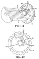
- Figs. 11 and 12 illustrate a third embodiment of the invention comprising three pins 6a, 6b, and 6c fixed to the locking ring 3.
- the wire is anchored to the spool spindle post 21 and is wound a multiple number of turns around two of the pins 6a and 6c and partly around the third pin 6b that is disposed between the first two pins.
- the wire unwinds from the multiple turns around pin 6a, 6b and 6c and is wound onto the spool spindle post 21.
- This arrangement provides a high level of load limiting.
- the wire may be wrapped any number of turns around each pin 6a, 6b, and 6c in the initial configuration and many possibilities are envisaged to tailor the load limiting response to the particular conditions required. It may be arranged so that the wire 4 is wrapped around the pins 6a, 6b and 6c initially but as load limiting progresses it may be drawn completely off the first pin 6a and/or the second pin 6b. This effectively provides for two stage load limiting because the load limiting is at a high level initially when the wire 4 is bent around each pin, and a lower level when the wire is unwound from the first pin 6a.
- the performance of the load limiting can be tailored by changing the number of coils wrapped around each pin, the angle of the winding, the wire diameter and the number of wires.
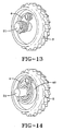
- Fig. 13 illustrates a fourth embodiment of the invention.
- the wire can be arranged to wrap radially or spirally along the axis of the pin or pins.
- the torque required to wind the wire reduces as the angle of the coil increases, and this characteristic can be further utilized to tailor the load limiting characteristics to suit the application.
- a single pin 6 is shown fixed to the locking ring and the wire 4 winds itself a plurality of times around the spindle post 21 in adjacently lying turns, i.e. spirally.
- the wire 4 may be coiled onto the spindle 21 in a radial fashion like a clock spring as illustrated in Fig. 14 where a guide element 40 is attached to the locking ring 3 to support the radial coils of wire 4.
- Figs. 15 and 16 two pins 6d and 6e are set diametrically opposite each other on either side of the spindle post 21.
- Fig. 15 illustrates this embodiment before load limiting with the wire attached to the spindle post 21 and coiled around each pin 6d and 6e a couple of times.
- Fig. 16 illustrates this embodiment after load limiting with the wire 4 unwound from one pin 6e and coiled onto the post 21. Again this effectively provides two-stage load limiting as explained below with reference to the graph shown in Fig. 17.
- Fig. 17 is a graph of load against displacement and the portion A relates to both pins 6d and 6e being engaged by a wire 4 whereas portion B relates to only the one pin 6d engaged by the wire 4.
- the wire is wound around the pin a multiple number of turns.
- the wire requires energy to deform it around the pin (this is known as the capstan effect) and this creates the load limiting effect.
- the end of the wire which is anchored may be attached to a spindle, preferably in the spool body and the wire will also wind around the spindle which therefore acts as a cable drum taking up the wire pulled around the pin and adding to the load limiting effect.
- the wire may be pre-formed from steel with a first straight portion or a slight curve followed by one or more coils and followed by a second straight portion.
- the pin can then be inserted through the coils and a block or stop fixed to the first straight portion to prevent the wire from uncoiling.
- An advantage of the present invention is that it is relatively inexpensive to implement and the load limiting effect can easily be changed by changing the diameter of the wire, the material of the wire, the number of turns of the wire around the pin, the pin diameter or the number of wires.
Landscapes
- Engineering & Computer Science (AREA)
- Mechanical Engineering (AREA)
- Automotive Seat Belt Assembly (AREA)
Claims (9)
- Sicherheitsgurtaufroller, der Folgendes umfasst:eine rotationsfähig im Aufroller montierte Spule (1) zum Aufrollen oder Ausziehen von Sicherheitsgurtband in Abhängigkeit von der Drehrichtung der Spule;einen an einem Ende der Spule (1) angebrachten Sperr-Ring (3);ein Sperrstück (10) zum Sperren des Sperr-Rings (3) gegen Drehung, wenn ein Aufprall erfasst wird, undein Kraftbegrenzungsmittel, das weiteres Ausziehen des Sicherheitsgurtbandes zulässt, nachdem der Sperr-Ring (3) unter dem Einfluss der Vorwärtsbewegung eines Fahrzeuginsassen blockiert hat, dadurch gekennzeichnet, dass das Kraftbegrenzungsmittel ein Stück Draht (4) umfasst, das an einem Ende von entweder der Spule (1) oder dem Sperr-Ring angebracht ist und in einer von dem genannten einen Ende beabstandeten Entfernung auf einen Stift (6; 6a, 6b, 6c) aufgewickelt ist, der jeweils umgekehrt an dem Sperr-Ring bzw. der Spule befestigt ist, so dass der Draht unter dem Einfluss von Aufprallkräften über einem vorbestimmten Wert um den Stift gezogen wird.
- Sicherheitsgurtaufroller nach Anspruch 1, der eine Mehrzahl von Stiften (6a, 6b, 6c) umfasst, die jeweils umgekehrt an dem Sperr-Ring (3) bzw. der Spule (1) befestigt sind.
- Sicherheitsgurtaufroller nach Anspruch 1 oder 2, bei dem der Draht (4) mit einer einzelnen Windung oder einer teilweisen Windung um wenigstens einen Stift (6; 6a, 6b, 6c) gewickelt ist.
- Sicherheitsgurtaufroller nach Anspruch 1 oder 2, bei dem der Draht (4) in einer Vielzahl von Windungen um wenigstens einen Stift (6; 6a, 6b, 6c) gewickelt ist.
- Sicherheitsgurtaufroller nach einem der Ansprüche 2 bis 4, bei dem der Draht (4) in einem Gemisch von einzelnen und mehreren Windungen um die Stifte (6; 6a, 6b, 6c) gewickelt ist, um den Lastbegrenzungseffekt auf den erforderlichen Grad für die vorgesehene Anwendung abzustimmen.
- Sicherheitsgurtaufroller nach einem der Ansprüche 1 bis 5, bei dem der Draht (4) mit einem ersten ungewendelten Abschnitt, einem zweiten gewendelten Abschnitt und einem dritten ungewendelten Abschnitt ausgebildet ist.
- Sicherheitsgurtaufroller nach einem der Ansprüche 1 bis 6, der ferner eine Spindel (20) umfasst, an der das verankerte Ende des Drahts (4) angebracht ist.
- Sicherheitsgurtaufroller nach Anspruch 7, bei dem sich der Draht (4) während der Lastbegrenzung auf die Spindel (20) aufwickelt, so dass die Spindel als Kabelrolle wirkt.
- Sicherheitsgurtaufroller nach einem der Ansprüche 1 bis 8, bei dem wenigstens ein Stift (6; 6a, 6b, 6c) durch wenigstens eine Wicklung im Draht (4) gesteckt ist und eine Blockierung oder ein Anschlag angebracht ist, um zu verhindern, dass sich der Draht abwickelt.
Applications Claiming Priority (3)
| Application Number | Priority Date | Filing Date | Title |
|---|---|---|---|
| GB0208699 | 2002-04-16 | ||
| GB0208699A GB2387574B (en) | 2002-04-16 | 2002-04-16 | Retractor |
| PCT/US2002/035267 WO2003089281A1 (en) | 2002-04-16 | 2002-11-04 | Seat belt retractor |
Publications (2)
| Publication Number | Publication Date |
|---|---|
| EP1494898A1 EP1494898A1 (de) | 2005-01-12 |
| EP1494898B1 true EP1494898B1 (de) | 2007-04-18 |
Family
ID=9934931
Family Applications (1)
| Application Number | Title | Priority Date | Filing Date |
|---|---|---|---|
| EP02789396A Expired - Lifetime EP1494898B1 (de) | 2002-04-16 | 2002-11-04 | Sicherheitsgurtaufroller |
Country Status (9)
| Country | Link |
|---|---|
| US (1) | US6712305B2 (de) |
| EP (1) | EP1494898B1 (de) |
| JP (1) | JP2006507964A (de) |
| KR (1) | KR100699653B1 (de) |
| CN (1) | CN1305716C (de) |
| AU (1) | AU2002353992A1 (de) |
| DE (1) | DE60219695T2 (de) |
| GB (1) | GB2387574B (de) |
| WO (1) | WO2003089281A1 (de) |
Families Citing this family (14)
| Publication number | Priority date | Publication date | Assignee | Title |
|---|---|---|---|---|
| JP4166096B2 (ja) * | 2003-01-31 | 2008-10-15 | 芦森工業株式会社 | シートベルトリトラクター |
| JP4166095B2 (ja) * | 2003-01-31 | 2008-10-15 | 芦森工業株式会社 | シートベルトリトラクター |
| DE102005026885B4 (de) * | 2005-06-10 | 2015-01-08 | Trw Automotive Gmbh | Kraftbegrenzer für einen Fahrzeug-Sicherheitsgurt |
| US20070120000A1 (en) * | 2005-11-30 | 2007-05-31 | Takata Seat Belts, Inc. | Seat belt retractor including an energy absorbing device |
| DE102006027897A1 (de) * | 2006-06-17 | 2007-12-27 | Volkswagen Ag | Sicherheitsgurteinrichtung für ein Kraftfahrzeug |
| US7784726B2 (en) * | 2006-12-31 | 2010-08-31 | Honda Motor Co., Ltd. | Multi-spool seatbelt retractor |
| US8006927B2 (en) * | 2009-05-29 | 2011-08-30 | Honda Motor Co., Ltd. | Attenuated seatbelt stopper |
| US9114779B2 (en) * | 2011-02-14 | 2015-08-25 | The United States Of America As Represented By The Secretary Of The Army | High voltage lithium ion positive electrode material with improved cycle life |
| JP6155116B2 (ja) * | 2013-06-28 | 2017-06-28 | 芦森工業株式会社 | シートベルト用リトラクタ |
| JP6126985B2 (ja) * | 2013-12-24 | 2017-05-10 | 株式会社東海理化電機製作所 | ウェビング巻取装置 |
| CN106143403B (zh) * | 2015-04-03 | 2020-07-28 | 天合汽车研发(上海)有限公司 | 限力卷收器 |
| JP6694765B2 (ja) * | 2016-06-09 | 2020-05-20 | 株式会社東海理化電機製作所 | ウェビング巻取装置 |
| CN112977326B (zh) * | 2021-04-06 | 2021-12-28 | 重庆光大产业有限公司 | 一种有效降低车辆乘员碰撞伤害的限力终止式卷收器 |
| US12441272B2 (en) * | 2022-10-19 | 2025-10-14 | Ford Global Technologies, Llc | Load limiting seatbelt retractor |
Family Cites Families (9)
| Publication number | Priority date | Publication date | Assignee | Title |
|---|---|---|---|---|
| JPS5619245U (de) * | 1979-07-19 | 1981-02-20 | ||
| GB2345891B (en) | 1996-01-24 | 2000-10-04 | Alliedsignal Ltd | Retractor spool |
| DE29614587U1 (de) | 1996-08-22 | 1996-12-19 | Trw Occupant Restraint Systems Gmbh, 73551 Alfdorf | Kraftbegrenzer für ein Sicherheitsgurtsystem |
| JPH11235967A (ja) * | 1998-02-19 | 1999-08-31 | Honda Motor Co Ltd | シートベルト巻取装置 |
| DE29816280U1 (de) | 1998-09-10 | 1999-01-21 | TRW Occupant Restraint Systems GmbH & Co. KG, 73553 Alfdorf | Vorrichtung zur Kraftbegrenzung |
| DE29922561U1 (de) | 1999-12-22 | 2000-05-04 | TRW Occupant Restraint Systems GmbH & Co. KG, 73553 Alfdorf | Kraftbegrenzer für Gurtaufroller |
| DE20007238U1 (de) * | 2000-04-19 | 2000-08-24 | TRW Occupant Restraint Systems GmbH & Co. KG, 73553 Alfdorf | Gurtaufroller für einen Fahrzeug-Sicherheitsgurt |
| JP3723423B2 (ja) | 2000-05-31 | 2005-12-07 | エヌエスケー・オートリブ株式会社 | シートベルト装置 |
| DE10040976C1 (de) * | 2000-08-22 | 2002-03-14 | Autoliv Dev | Gurtaufroller mit einem einen einstellbaren Torsionskraftverlauf ermöglichenden Torsionsstab |
-
2002
- 2002-04-16 GB GB0208699A patent/GB2387574B/en not_active Expired - Fee Related
- 2002-08-19 US US10/222,880 patent/US6712305B2/en not_active Expired - Fee Related
- 2002-11-04 WO PCT/US2002/035267 patent/WO2003089281A1/en not_active Ceased
- 2002-11-04 AU AU2002353992A patent/AU2002353992A1/en not_active Abandoned
- 2002-11-04 JP JP2003586009A patent/JP2006507964A/ja active Pending
- 2002-11-04 CN CNB028285646A patent/CN1305716C/zh not_active Expired - Fee Related
- 2002-11-04 EP EP02789396A patent/EP1494898B1/de not_active Expired - Lifetime
- 2002-11-04 DE DE60219695T patent/DE60219695T2/de not_active Expired - Lifetime
- 2002-11-04 KR KR1020047016474A patent/KR100699653B1/ko not_active Expired - Fee Related
Also Published As
| Publication number | Publication date |
|---|---|
| US20030192975A1 (en) | 2003-10-16 |
| EP1494898A1 (de) | 2005-01-12 |
| CN1305716C (zh) | 2007-03-21 |
| KR100699653B1 (ko) | 2007-03-23 |
| US6712305B2 (en) | 2004-03-30 |
| JP2006507964A (ja) | 2006-03-09 |
| GB2387574A (en) | 2003-10-22 |
| GB0208699D0 (en) | 2002-05-29 |
| KR20040097361A (ko) | 2004-11-17 |
| AU2002353992A1 (en) | 2003-11-03 |
| WO2003089281A1 (en) | 2003-10-30 |
| DE60219695D1 (de) | 2007-05-31 |
| DE60219695T2 (de) | 2007-12-27 |
| CN1622887A (zh) | 2005-06-01 |
| GB2387574B (en) | 2004-05-19 |
Similar Documents
| Publication | Publication Date | Title |
|---|---|---|
| US6739541B2 (en) | Seat belt retractor with load limiting | |
| US6669133B2 (en) | Seat belt retractor with multi-level load limiting | |
| EP1494898B1 (de) | Sicherheitsgurtaufroller | |
| US7025297B2 (en) | Seat belt retractor | |
| US6302346B1 (en) | Seat belt webbing energy management device | |
| EP1024064A2 (de) | Bobine d'enrouleur | |
| US20030019969A1 (en) | Selectable load limiting seat restraint retractor | |
| US9079565B2 (en) | Progressive load limiting restraint system | |
| EP1494896B1 (de) | Sicherheitsgurtaufroller | |
| JP4308402B2 (ja) | ウェビング巻取装置 | |
| US6042042A (en) | Seat belt retractor |
Legal Events
| Date | Code | Title | Description |
|---|---|---|---|
| PUAI | Public reference made under article 153(3) epc to a published international application that has entered the european phase |
Free format text: ORIGINAL CODE: 0009012 |
|
| 17P | Request for examination filed |
Effective date: 20040906 |
|
| AK | Designated contracting states |
Kind code of ref document: A1 Designated state(s): AT BE BG CH CY CZ DE DK EE ES FI FR GB GR IE IT LI LU MC NL PT SE SK TR |
|
| GRAP | Despatch of communication of intention to grant a patent |
Free format text: ORIGINAL CODE: EPIDOSNIGR1 |
|
| GRAS | Grant fee paid |
Free format text: ORIGINAL CODE: EPIDOSNIGR3 |
|
| GRAA | (expected) grant |
Free format text: ORIGINAL CODE: 0009210 |
|
| AK | Designated contracting states |
Kind code of ref document: B1 Designated state(s): DE FR IT |
|
| REF | Corresponds to: |
Ref document number: 60219695 Country of ref document: DE Date of ref document: 20070531 Kind code of ref document: P |
|
| ET | Fr: translation filed | ||
| PLBE | No opposition filed within time limit |
Free format text: ORIGINAL CODE: 0009261 |
|
| STAA | Information on the status of an ep patent application or granted ep patent |
Free format text: STATUS: NO OPPOSITION FILED WITHIN TIME LIMIT |
|
| 26N | No opposition filed |
Effective date: 20080121 |
|
| PGFP | Annual fee paid to national office [announced via postgrant information from national office to epo] |
Ref country code: FR Payment date: 20101109 Year of fee payment: 9 |
|
| PGFP | Annual fee paid to national office [announced via postgrant information from national office to epo] |
Ref country code: DE Payment date: 20101130 Year of fee payment: 9 |
|
| PGFP | Annual fee paid to national office [announced via postgrant information from national office to epo] |
Ref country code: IT Payment date: 20101119 Year of fee payment: 9 |
|
| REG | Reference to a national code |
Ref country code: FR Ref legal event code: ST Effective date: 20120731 |
|
| PG25 | Lapsed in a contracting state [announced via postgrant information from national office to epo] |
Ref country code: IT Free format text: LAPSE BECAUSE OF NON-PAYMENT OF DUE FEES Effective date: 20111104 |
|
| REG | Reference to a national code |
Ref country code: DE Ref legal event code: R119 Ref document number: 60219695 Country of ref document: DE Effective date: 20120601 |
|
| PG25 | Lapsed in a contracting state [announced via postgrant information from national office to epo] |
Ref country code: FR Free format text: LAPSE BECAUSE OF NON-PAYMENT OF DUE FEES Effective date: 20111130 |
|
| PG25 | Lapsed in a contracting state [announced via postgrant information from national office to epo] |
Ref country code: DE Free format text: LAPSE BECAUSE OF NON-PAYMENT OF DUE FEES Effective date: 20120601 |