EP1494902B1 - Levier d'essuie-glace muni d'un bras d'essuie-glace et d'un balai d'essuie-glace articule dessus - Google Patents
Levier d'essuie-glace muni d'un bras d'essuie-glace et d'un balai d'essuie-glace articule dessus Download PDFInfo
- Publication number
- EP1494902B1 EP1494902B1 EP03722240A EP03722240A EP1494902B1 EP 1494902 B1 EP1494902 B1 EP 1494902B1 EP 03722240 A EP03722240 A EP 03722240A EP 03722240 A EP03722240 A EP 03722240A EP 1494902 B1 EP1494902 B1 EP 1494902B1
- Authority
- EP
- European Patent Office
- Prior art keywords
- adapter
- wiper
- lever according
- limbs
- locking means
- Prior art date
- Legal status (The legal status is an assumption and is not a legal conclusion. Google has not performed a legal analysis and makes no representation as to the accuracy of the status listed.)
- Expired - Lifetime
Links
- 238000009434 installation Methods 0.000 claims description 3
- 239000013013 elastic material Substances 0.000 claims description 2
- 230000013011 mating Effects 0.000 claims 9
- 238000004140 cleaning Methods 0.000 claims 2
- 230000010355 oscillation Effects 0.000 claims 1
- 210000002105 tongue Anatomy 0.000 description 13
- 230000008878 coupling Effects 0.000 description 10
- 238000010168 coupling process Methods 0.000 description 10
- 238000005859 coupling reaction Methods 0.000 description 10
- 238000013459 approach Methods 0.000 description 4
- 238000013461 design Methods 0.000 description 4
- 238000011161 development Methods 0.000 description 4
- 230000018109 developmental process Effects 0.000 description 4
- 238000010276 construction Methods 0.000 description 3
- 210000000078 claw Anatomy 0.000 description 2
- 230000001105 regulatory effect Effects 0.000 description 2
- 230000003750 conditioning effect Effects 0.000 description 1
- 238000006073 displacement reaction Methods 0.000 description 1
- 238000009826 distribution Methods 0.000 description 1
- 230000007613 environmental effect Effects 0.000 description 1
- 238000003780 insertion Methods 0.000 description 1
- 230000037431 insertion Effects 0.000 description 1
- 238000004519 manufacturing process Methods 0.000 description 1
- 238000000034 method Methods 0.000 description 1
- 230000006641 stabilisation Effects 0.000 description 1
- 238000011105 stabilization Methods 0.000 description 1
- 230000000087 stabilizing effect Effects 0.000 description 1
- 238000003860 storage Methods 0.000 description 1
- 230000001960 triggered effect Effects 0.000 description 1
- 238000005406 washing Methods 0.000 description 1
Images


Classifications
-
- B—PERFORMING OPERATIONS; TRANSPORTING
- B60—VEHICLES IN GENERAL
- B60S—SERVICING, CLEANING, REPAIRING, SUPPORTING, LIFTING, OR MANOEUVRING OF VEHICLES, NOT OTHERWISE PROVIDED FOR
- B60S1/00—Cleaning of vehicles
- B60S1/02—Cleaning windscreens, windows or optical devices
- B60S1/04—Wipers or the like, e.g. scrapers
- B60S1/32—Wipers or the like, e.g. scrapers characterised by constructional features of wiper blade arms or blades
- B60S1/38—Wiper blades
- B60S1/3848—Flat-type wiper blade, i.e. without harness
- B60S1/3849—Connectors therefor; Connection to wiper arm; Attached to blade
- B60S1/3865—Connectors having an integral pivot pin for connection with the wiper arm
- B60S1/3868—Connectors having an integral pivot pin for connection with the wiper arm pin formed on the exterior of side walls
-
- B—PERFORMING OPERATIONS; TRANSPORTING
- B60—VEHICLES IN GENERAL
- B60S—SERVICING, CLEANING, REPAIRING, SUPPORTING, LIFTING, OR MANOEUVRING OF VEHICLES, NOT OTHERWISE PROVIDED FOR
- B60S1/00—Cleaning of vehicles
- B60S1/02—Cleaning windscreens, windows or optical devices
- B60S1/04—Wipers or the like, e.g. scrapers
- B60S1/32—Wipers or the like, e.g. scrapers characterised by constructional features of wiper blade arms or blades
- B60S1/38—Wiper blades
-
- B—PERFORMING OPERATIONS; TRANSPORTING
- B60—VEHICLES IN GENERAL
- B60S—SERVICING, CLEANING, REPAIRING, SUPPORTING, LIFTING, OR MANOEUVRING OF VEHICLES, NOT OTHERWISE PROVIDED FOR
- B60S1/00—Cleaning of vehicles
- B60S1/02—Cleaning windscreens, windows or optical devices
- B60S1/04—Wipers or the like, e.g. scrapers
- B60S1/32—Wipers or the like, e.g. scrapers characterised by constructional features of wiper blade arms or blades
- B60S1/40—Connections between blades and arms
- B60S1/4038—Connections between blades and arms for arms provided with a channel-shaped end
-
- B—PERFORMING OPERATIONS; TRANSPORTING
- B60—VEHICLES IN GENERAL
- B60S—SERVICING, CLEANING, REPAIRING, SUPPORTING, LIFTING, OR MANOEUVRING OF VEHICLES, NOT OTHERWISE PROVIDED FOR
- B60S1/00—Cleaning of vehicles
- B60S1/02—Cleaning windscreens, windows or optical devices
- B60S1/04—Wipers or the like, e.g. scrapers
- B60S1/32—Wipers or the like, e.g. scrapers characterised by constructional features of wiper blade arms or blades
- B60S1/38—Wiper blades
- B60S1/3848—Flat-type wiper blade, i.e. without harness
- B60S1/3849—Connectors therefor; Connection to wiper arm; Attached to blade
- B60S1/3851—Mounting of connector to blade assembly
- B60S1/3856—Gripping the blade
-
- B—PERFORMING OPERATIONS; TRANSPORTING
- B60—VEHICLES IN GENERAL
- B60S—SERVICING, CLEANING, REPAIRING, SUPPORTING, LIFTING, OR MANOEUVRING OF VEHICLES, NOT OTHERWISE PROVIDED FOR
- B60S1/00—Cleaning of vehicles
- B60S1/02—Cleaning windscreens, windows or optical devices
- B60S1/04—Wipers or the like, e.g. scrapers
- B60S1/32—Wipers or the like, e.g. scrapers characterised by constructional features of wiper blade arms or blades
- B60S1/38—Wiper blades
- B60S2001/3812—Means of supporting or holding the squeegee or blade rubber
- B60S2001/3817—Means of supporting or holding the squeegee or blade rubber chacterised by a backing strip to aid mounting of squeegee in support
- B60S2001/382—Means of supporting or holding the squeegee or blade rubber chacterised by a backing strip to aid mounting of squeegee in support the backing strip being an essentially planar reinforcing strip, e.g. vertebra
-
- B—PERFORMING OPERATIONS; TRANSPORTING
- B60—VEHICLES IN GENERAL
- B60S—SERVICING, CLEANING, REPAIRING, SUPPORTING, LIFTING, OR MANOEUVRING OF VEHICLES, NOT OTHERWISE PROVIDED FOR
- B60S1/00—Cleaning of vehicles
- B60S1/02—Cleaning windscreens, windows or optical devices
- B60S1/04—Wipers or the like, e.g. scrapers
- B60S1/32—Wipers or the like, e.g. scrapers characterised by constructional features of wiper blade arms or blades
- B60S1/40—Connections between blades and arms
- B60S1/4038—Connections between blades and arms for arms provided with a channel-shaped end
- B60S1/4045—Connections between blades and arms for arms provided with a channel-shaped end comprising a detachable intermediate element mounted on the channel-shaped end
- B60S1/4048—Connections between blades and arms for arms provided with a channel-shaped end comprising a detachable intermediate element mounted on the channel-shaped end the element being provided with retention means co-operating with the channel-shaped end of the arm
- B60S2001/4051—Connections between blades and arms for arms provided with a channel-shaped end comprising a detachable intermediate element mounted on the channel-shaped end the element being provided with retention means co-operating with the channel-shaped end of the arm the intermediate element engaging the side walls of the arm
Definitions
- the invention relates to a wiper lever according to the type defined in claim 1.
- the wiper lever comprises a driven wiper arm, on which at a distance from its drive end a wiper blade which is displaceable transversely to its longitudinal extent via the wiper disk to be wiped is articulated.
- the hinge axis of the wiper blade extends substantially in its direction of displacement. This joint is of particular importance because the disc to be wiped, usually spherically curved disc, for example, the windshield of a motor vehicle is not a portion of a spherical surface. It must therefore be able to adjust the wiper blade during its wiping movement constantly the respective position and the course of the disc surface with respect to the plane of movement of the wiper arm.
- a swinging movement of the wiper blade relative to the wiper arm to the mentioned hinge axis is required.
- a known generic wiper lever DE-OS 10065124
- WO-A-02/053421 falls under Art. 54 (3) EPC 1973
- the wiper blade is provided for this purpose via a joint part fixedly connected to it with suitably aligned pivot pins to which an adapter belonging to the wiper blade is articulated, via which the wiper blade can be connected to the wiper arm.
- Locking means present on the adapter should, in cooperation with counter-locking means of the wiper arm, ensure a reliable connection between the wiper arm and the wiper blade.
- the walls are formed by the two U-legs of the adapter.
- the U-base forming wall of the adapter is provided with a parallel to the orientation of the walls elastically deflectable, a locking tooth having tongue extending beyond the Wischerarmende out, said acting as a locking means locking tooth with counter locking means of the wiper arm in Cooperates meaning a releasable wiper blade fuse.
- the exposed tongue can also be unintentionally so deflected - for example, by the rotating brushes in vehicle washing systems - that the wiper blade from the wiper arm dissolves and causes damage to the vehicle.
- the object of the invention without restriction, because the access for such an action is also visually exposed and the release movement does not require difficult hand movements.
- the transverse movement required to release the lock can not be triggered by the brushes of a car wash.
- the adapter at least partially has a U-shaped cross-section whose U-legs form the two walls, dipped between which formed on the hinge part support walls suitable.
- each U-leg of the adapter is provided on its outside with a bearing receptacle surrounding, collar-like approach, the one at least partially adapted to the contour of the approach, the free end of the respective U- Schenkel's open recess is assigned.
- the oscillatingly driven wiper arm receives the adapter with a cross-sectionally U-shaped connecting part and extends the extension of the adapter to the pendulum axis, this results in a compact construction of the articulated connection with integrated connecting means.
- the locking itself can then be achieved in a particularly simple manner, that are formed on the adapter at a distance from each other in the longitudinal direction of each other oppositely directed stops, which are assigned to the connection part of the wiper arm existing counterstops.
- Such an arrangement also ensures the necessary securing of the wiper blade on the wiper arm in its longitudinal direction.
- At least one of the attacks located on the adapter is formed by its locking means.
- a simple, weight-saving joint is achieved if this comprises two projecting from the two longitudinal walls of the joint part hinge pin whose axes are aligned with each other and assigned by the hinge pin, arranged in the U-legs of the adapter bearing receivers, each having a at the free end of the U-leg opening, matched to the diameter of the respective hinge pin mounting channel are open-edge.
- each mounting channel is provided with an elastically expandable constriction.
- a simplification of the hinge connection and the configuration of the locking means between wiper arm and wiper blade is achieved when the collar-like projections together with the adapted to the course section of the recesses which form a stop and counter stops.
- the adapter is provided on at least one of its U-legs with a locking tooth having, elastically deflectable tongue, wherein the locking means forming a locking tooth has a collar-like approach stop shoulder, which cooperates with a formed on the connecting part, facing away from the collar-like approach counter-attack shoulder.
- the collar-like projection associated recess in the U-legs of the connecting part of its opening at the free end of the U-legs of a curved to the counter-stop shoulder course is thereby under attacked in its operating position to be locked by a remaining wall tongue of the connecting part and set the position of the adapter in the connection part.
- pin-like supports are arranged on the longitudinal end region remote from the locking means. each of which is associated with a formed on the front side of the U-legs of the connecting part support bearing.
- the position of the wiper blade in the longitudinal direction of the wiper arm in this operating position is fixed in a simple manner, when the locking tooth of the adapter is provided with a pointing away from the U-base of the adapter retaining shoulder, which assigned to the connection part, pointing to the U-base counter-retaining shoulder is.
- Such an assembly aid can be inexpensively achieved in that the guide means of the wiper blade are formed by an existing in the U-legs of the adapter, at its U-base opening groove-like link guide, in which the arranged on the connector part, formed as a guide pin guide means dive.
- the course of the slotted guide can be adapted to the respective requirements, so that assembly errors are excluded.
- a smooth merging of wiper blade or adapter and the connection part of the wiper arm results when the guide is provided at its mouth with a funnel-like extension.
- the collar-like projection rests against a support shoulder pointing to the free end of the U-leg against a counter-shoulder of the connection part.
- a laterally projecting handle is arranged on the connecting means of the adapter having extension of the U-legs.
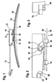
- Wiper lever 10 shown include a wiper arm 12 and a wiper blade 14 hinged thereto.
- the wiper arm 12 is driven in a pendulum fashion about its axis at one end.
- the wiper arm is provided at its other, free end with a coupling piece 18 ( FIGS. 1 and 4 ), to which the wiper blade 14 can be connected with a joint part 20 via an adapter.
- the joint part 20 is fixedly connected to a support element 22 of the wiper blade 14, which in the embodiment has two in a common plane and spaced apart, dash-dotted lines spring rails 24 ( FIG. 2 ).
- the band-shaped elongated, resilient support element 22 thus formed is curved in its longitudinal direction over its band surfaces 26 and 28 (FIG. FIG. 1 ).
- band surfaces 26 and 28 At its concave curved band surface 26 is arranged on the disc to be wiped 15 in the direction of arrow 17, rubber-elastic wiper strip 30 is disposed and at its other, convexly curved band surface 28 sits the hinge part 20.
- This arrangement is in particular FIG. 8 clearly visible where the wiper strip 30 is shown by dash-dotted lines.
- the joint part has 20 a longitudinal wall 32, the two opposite longitudinal cheeks 34 form guide surfaces or retaining walls.
- the longitudinal wall 32 is provided with retaining claws 36 which engage around the mutually remote longitudinal edges of the two spring rails 24 and secure the two spring rails 24 in the required installation position. This can be done by positive and / or non-positive acting means. Further, it is conceivable to weld the joint part 20 in the region of the retaining claws 36 with the spring rails 24. From the longitudinal wall 32 and from the longitudinal cheeks 34 projecting on both sides each a transversely to the longitudinal direction of the longitudinal wall aligned, the wiper blade side hinge means forming pivot pin 38, of which FIG. 4 however, only the one, on the side facing the viewer facing pivot pin is visible. The axes of the two pivot pin 38 are aligned.
- the adapter 40 has a substantially U-shaped cross-section ( FIG. 4 ), whose both walls forming U-legs 42 extend from the U-base 44 from the support member 22.
- the distance between the two U-legs 42 is matched to the thickness of the longitudinal wall 32, that this can be accommodated with little play between the two legs 42 ( FIG. 8 ).
- the two U-legs 42 are provided with open to their free ends edge-open mounting channels or receiving slots 46, which pass over a respective restriction 48 in bearing mounts 50 for the pivot pin 38.
- the coupling piece 18 of the wiper arm 12 also has a U-shaped cross section which is dimensioned so that the guide walls 54 formed on the U-legs 52 of the coupling piece 18 for the wiper blade at a distance 55 from each other are suitably matched to the width 56 of the adapter 40.
- the U-base wall 58 of the coupling piece 18 practically forms a cover for the hinge connection.
- the adapter 40 the playfully free or at least low-play between the U-legs 42 receives the longitudinal wall 32 of the joint part 20 and beyond the facing guide walls 54 on the U-legs 52 of the coupling piece 18, the U-legs 42 also overlap play, This results in an excellent guide for the wiper blade when it is moved transversely to its longitudinal extent on the disc 15 to be wiped.
- a possible play-free guidance of the wiper blade on the wiper arm is sought, because such counteracts the Ratterneist the wiper blade 14 on the disc 15.
- the adapter 40 has at its two facing away from each other outer leg cheeks each have a collar-like projection 60 which surrounds the respective bearing seat 50.
- This collar-like projection 60 increases the bearing surface of the bearing receptacles 50 and also leads to a stabilization of the adapter 40 at least in the area where the receiving slots 46 are arranged for the hinge pin or pivot pin 38 of the joint part 20.
- These two collar-like projections 60 are each assigned an open-edged recess 62 in the guide walls 54 having U-legs 52 of the coupling piece 18.
- the recesses 62 open at the free ends of the U-legs 52.
- the end portions 63 of the recesses 62 are adapted in shape to the contours of the lugs 60.
- the course of the recesses 62 is curved so that their end portions 63 are closer to the pendulum axis 16 of the wiper arm 12 than the mouths 61 at the free ends of the U-legs 52.
- the course of the necessary curvature is designed so that in border area each U-leg 52 remains a securing tongue 64 which extends from the end portion 63 of the recess 62 to the mouth 61 of the recess 62 ( FIG. 4 ).
- a counter-stop shoulder 66 is formed on the coupling piece 18, which faces the pendulum axis 16.
- This counter-stop shoulder 66 is associated with a stop shoulder 68, which is formed on the adapter 40.
- 40 elastically deflectable extensions or tongues 70 are located on each of the two U-legs 42 of the adapter, on the outer sides of each of which a latching tooth 72 is located.
- At each of the ratchet teeth 72 are the abovementioned stop shoulders 68, which point to the collar-like projections 60 ( FIG. 4 ).
- the adapter 40 of the wiper blade in the direction of the arrow 49 is first applied to the hinge part 20 of the wiper blade 14 for its assembly.
- the constriction 48 in the U-legs 42 of the adapter 40 reach the pivot pin 38 of the joint part 20 via serving as a mounting channel receiving slots 46 in their bearing mounts 50.
- the dimensional adjustment of these components is made such that the adapter to the common axis of the pivot pin 38 is pendelbar within certain limits.
- the tongues 70 extend beyond the longitudinal wall 32 of the articulated part 20, so that they can be moved by overcoming a restoring force essentially transversely to the longitudinal cheeks or surfaces 34 of the longitudinal wall 32 facing away from one another.
- the wiper blade 14 with its adapter 40 is now introduced between the U-legs 52 of the coupling part 18 of the wiper arm 12 serving as a connection part.
- the collar-like projections 60 are introduced via the mouths 61 into the recesses 62 until the collar walls 59 abut against the end regions 63 of the recesses 62.
- the tongues 70 arranged on the walls or on the U-limbs 42 of the adapter 40 are manually deflected toward one another - ie transversely to the surfaces 34 - so that the locking teeth 72 can likewise reach between the U-limbs 52 of the connection part 18 .
- the stop shoulders 68 of the locking teeth 72 pass beyond the counter stop shoulders 66 and spring back into their starting position.
- the stop shoulders 68 hook-like engage behind the counterstop shoulders 66 (FIG. FIGS. 2 and 3 ).
- the wiper blade 14 is fixed to the wiper arm 12 in the longitudinal direction, because the distance between the end portions 63 and the counter-stop shoulders 66 is matched to the distance between the stop shoulders 68 and the collar walls 59.
- the stop shoulders 68 facing areas of the collar walls 59 together with these mutually facing positioning shoulders, which are assigned to each other weg josden counter shoulders - formed by the end portions 63 of the recesses 62 and the counter stop shoulders 66 ( FIG. 2 ).
- the two tongues 70 of the adapter 40 must be deflected towards each other (arrows 74 in FIG FIG. 4 ) until their counter stop shoulders 68 release the stop shoulders 66 of the connector 18. Thereafter, the wiper blade can be pressed towards the free end of the wiper arm until the lugs 60 emerge from the recesses 62, so that the wiper blade 14 is released from the wiper arm.
- the hinge part 20 corresponds to the hinge part described above.
- the adapter 140 has a U-shaped cross-section with U-legs 142, which are provided with open-edge receiving slots 146.
- the constrictions 148 open the receiving slots 146 in bearing mounts 150 for the pivot pin 38 of the joint part 20.
- Collar-like projections 160 surround the bearing receivers 150 and improve the stability of the adapter and the storage of the pivot pin. Deviating from the previously described embodiment of the invention extend in the embodiment according to the FIGS.
- the adapter deflectable tongues 152 of the U-base 144 of the adapter 140 in the direction of the height of the U-legs 142, which constitute walls between which the support walls formed on the hinge part 20 dive suitably.
- the tongues 152 are formed by extensions of the U-legs 142.
- a latching tooth 154 is arranged in each case. These ratchet teeth extend from their tongues 152 in opposite directions. They are at their the U-base 144 facing Top provided with chamfers 155.
- this has peg-like supports 156 which are arranged on the outer side of each U-leg 142 and which likewise extend away from one another and are each provided with a rounding on their sides facing the collar-like projections 160 , Associated with these curves are recesses 158 serving as support bearings, on the end sides of the U-legs 159 of the U-shaped connecting part 118. Furthermore, the U-legs of the connecting part 118 are provided with collar-like projections 160, which are connected to the free ends of the U-shaped connection part 118. Leg are associated with open-edged recesses 161.
- the recesses 161 each have a shoulder 162 pointing toward the support bearings 158. Relative to the recesses 161, there are provided notches 163 opposite the support bearings 158 in the U-legs 160, which are assigned to the latching teeth 154 of the adapter 140 (FIG. FIG. 5 ).
- the shape of the recesses 161 is adapted at the central region 161 the course of the collar walls 164.
- the adapter 140 When assembling the wiper lever - as already described - first the adapter 140 is pivotally connected to the hinge part 20. Thereafter, according to FIG. 6 the wiper blade with its adapter 140 attached to the connection part 118 of the wiper arm such that the peg-like supports 156 lie in the support bearings 158 ( FIG. 6 ). Thereafter, the wiper blade is pivoted in the direction of the arrow 170 with respect to the wiper arm about a pivot axis of the peg-like supports 156, wherein the collar-like projections dive into their associated recesses 161 in the U-legs 159 of the connection part 118.
- the chamfers 155 of the locking teeth 154 abut against the free ends of the U-legs 159 and are elastically deflected towards each other until they reach the notches 163 in the U-legs 159 after completion of the pivoting movement (arrow 170).
- the ratchet teeth 154 spring back into their original position ( FIGS. 7 and 8th ).
- Arranged on the ratchet teeth 154, pointing away from the U-base of the adapter retaining shoulders 165 cooperate with formed on the notches 163 Yuhalteschultern 166 so that against the arrow 164 directed release movement between the wiper arm 12, 118 and the wiper blade 14 is excluded.
- stop shoulders 167 pointing to the collar-like projections 160 are present on the ratchet teeth 154, which cooperate with counter-stop shoulders 168 of the notches 163 assigned to them.
- the additional shoulders required for the longitudinal locking of the wiper blade on the wiper arm can either be through the shoulder 162 and the collar-like projection 160 may be formed and / or realized by the peg-like supports 156 and their support bearings 158.
- the locking means are arranged on at least one of the two walls or legs 142 of the adapter 140 and movable substantially transversely to the surfaces of these walls.
- FIGS. 9 to 12 Another embodiment of the invention is in the FIGS. 9 to 12 shown.
- the joint part 20 of the wiper blade corresponds in terms of the invention completely to the hinge part already described above.
- the adapter 240 corresponds in basic construction to the adapter 40 according to FIG. 4 , So he also has a U-shaped cross-section with U-legs 242 and arranged in the U-legs, to the free ends of open-edge recesses 244 for receiving the pivot pin 38 of the joint part 20.
- the course of the recesses 244 is arranged so that their Mouths 246 are further away from stop shoulders 248 than the bearing receptacles 250 located at the ends of the recesses 244 for the pivot pins 38 of the hinge part 20.
- the recesses 244 are each provided with an elastically expandable constriction 252 Mistake. Furthermore, the recesses 244 have collar-like projections 272 which extend along the entire edge of the respective recess.
- the stop shoulders 248 are arranged on tongue-like extensions 254 of the U-legs 242 and dimensioned so that they extend with stop shoulders 248 on the longitudinal wall 32 of the joint part 20 addition. Thus, the stop shoulders are each movable against a restoring force substantially transverse to the surfaces of the U-legs or walls 242 of the adapter 240 (arrows 287 in FIG. 10 ).
- the tongue-like extension 254 are still each provided with handles 256.
- the adapter 240 has guide slots 260 in the middle area, which extend from the U-base 258 of the U-shaped adapter 240 to the free ends of the U-legs 242.
- a stabilizing ridge 262 remains between the guide slots 260 in each U-leg 242.
- the course of the guide slots 260 is selected to extend from their mouths at the U-base 258, at their stop shoulders 248 facing sides with the U-base include an obtuse angle ⁇ ( FIG. 10 ).
- the groove-like guide slots 260 are each provided with a funnel-like widening 264. As in particular from FIG.
- the U-legs 266 of the wiper arm connection part 268 also open-edged recesses 270 for the collar-like projections 272 of the adapter 240, which are open to the free ends of the U-legs 266 down.
- the end portions 274 of these channel-shaped recesses 270 are closer to counter stop shoulders 276, which are formed on the U-legs 266 of the connecting part 268 and point away from the base or end regions 274 of the recesses 270.
- the counter-abutment shoulders 276 are formed on recesses 278 in the U-legs 266 of the connecting part 268.
- guide pins 280 are arranged, which have been formed in the embodiment of the U-legs and pushed inward.
- the diameters of these guide pins 280 are matched to the width of the guide slots 260.
- the adapter 240 When the adapter 240 is to be connected to the hinge part 20, its pivot pins 38 are inserted into their recesses 244 in the U-legs 242 of the adapter 240 until they reach their bearing seats 250 after overcoming the constriction 252 ( FIG. 10 ). Now, the adapter 240 is pendulum but captively connected to the joint part 20 and ready for the final assembly of the wiper lever 10. For this purpose, the adapter 240 is inserted between the U-legs 266 of the connecting part 268 such that the guide pins 280 pass through the funnel-like extensions 264 into the guide slots 260. This pre-assembly position is in FIG. 12 shown enlarged, wherein the assembly movement is indicated by the arrow 282.
- each wiper lever or each wiper blade is provided with locking means which are arranged on at least one of the two adapter walls and movable substantially transversely to the surfaces of these walls. Due to the arrangement of the locking devices in the region between the pendulum axis 16 of the wiper arm and the pivot axis of the wiper blade formed by the pivot pin 38, these are located in a lying below the wiper arm 12 level and are thus largely protected against unintentional operation in particular release movement.
Landscapes
- Engineering & Computer Science (AREA)
- Mechanical Engineering (AREA)
- Pivots And Pivotal Connections (AREA)
- Transmission Devices (AREA)
Claims (23)
- Levier d'essuie-glace (10) comportant un bras d'essuie-glace (12) portant de manière articulée un balai d'essuie-glace (14) pour nettoyer les vitres (15) notamment celles de véhicules automobiles, comportant un élément de support (22) en forme de bande, allongé, élastique comme un ressort et dont les surfaces de bande (26, 28) sont cintrées dans la direction longitudinale, sa surface de bande (28) cintrée de manière concave portant une lame d'essuie-glace (30) élastique comme du caoutchouc, appliquée contre la vitre (15) et sa surface de bande (28) à courbure convexe étant munie d'une pièce d'articulation (20) à laquelle est articulé de manière pendulaire un adaptateur (40) ayant des parois s'étendant dans la direction longitudinale du balai d'essuie-glace, dans une position debout par rapport aux surfaces de bande de l'élément de support et ces parois sont écartées l'une de l'autre, l'adaptateur portant des moyens de verrouillage (68, 70), mobiles, coopérant avec des moyens de verrouillage complémentaires (66) du bras d'essuie-glace,
caractérisé en ce que
les moyens de verrouillage sont prévus sur au moins l'une des deux parois latérales (42) et ils sont mobiles principalement dans la direction transversale aux surfaces de ces parois,
l'adaptateur (40) ayant au moins par segments, une section en forme de U dont les branches (42) de la forme en U constituent les deux parois entre lesquelles se logent de manière ajustée les parois d'appui (34) réalisées sur la pièce d'articulation (20), et les moyens d'articulation de l'adaptateur (40) sont formés par des logements de palier (50) prévus dans les branches (42) en forme de U, ces logements débouchant au niveau de l'extrémité libre des branches (42) en forme de U en débouchant sur le bord par un canal de montage (46) correspondant au diamètre du goujon d'articulation (38) respectif. - Levier d'essuie-glace selon la revendication 1,
caractérisé en ce que
l'adaptateur (40) chevauche de manière ajustée deux parois longitudinales (34) écartées l'une de l'autre et appartenant à la pièce d'articulation (20) par ses branches (42) en forme de U,
les moyens d'articulation (50, 38) sont prévus sur les parois longitudinales et sur les branches (42) en forme de U, et
les moyens de verrouillage (72) de l'adaptateur (40) réalisés en une matière élastique, se trouvent sur un prolongement (70) des branches en U de l'adaptateur s'étendant au-delà des parois longitudinales (34). - Balai d'essuie-glace selon la revendication 2,
caractérisé en ce que
le bras d'essuie-glace (12) entraîné suivant un mouvement pendulaire reçoit l'adaptateur (40) par une pièce de raccordement (18) ayant une section en forme U et le prolongement (70) de l'adaptateur s'étend en direction de l'axe (16) du mouvement pendulaire. - Balai d'essuie-glace selon la revendication 3,
caractérisé en ce que
les moyens de verrouillage (72) de l'adaptateur (40), mobiles de préférence contre une force de rappel, se trouvent sur le côté extérieur du prolongement (70) tourné vers les branches en forme de U (52) de la pièce de raccordement (18), qui portent les moyens de verrouillage complémentaires (66) du bras d'essuie-glace (12). - Balai d'essuie-glace selon les revendications 1 à 4,
caractérisé en ce que
l'adaptateur (40) comporte des butées (59, 68) écartées l'une de l'autre et opposées dans sa direction longitudinale, et la pièce de raccordement (18) du bras d'essuie-glace (12) comporte des butées complémentaires (63, 66) correspondantes. - Balai d'essuie-glace selon la revendication 5,
caractérisé en ce qu'
au moins l'une des butées de l'adaptateur (40) est constituée par ses moyens de verrouillage (72). - Balai d'essuie-glace selon les revendications 1 à 6,
caractérisé par
des moyens de verrouillage (72) prévus sur chacune des deux branches (42) en forme de U de l'adaptateur (40). - Balai d'essuie-glace selon les revendications 3 à 7,
caractérisé en ce que
chacune des deux branches (52) en forme de U de la pièce de raccordement (18) comporte des moyens de verrouillage complémentaires (66) coopérant avec les moyens de verrouillage (72) de l'adaptateur (40). - Balai d'essuie-glace selon les revendications 1 à 8,
caractérisé en ce que
les moyens d'articulation de la pièce d'articulation (20) sont constitués chacun par un goujon d'articulation (38) associé à chacune des parois longitudinales (34), les axes des goujons étant alignés. - Balai d'essuie-glace selon les revendications précédentes,
caractérisé en ce que
chaque canal de montage (46) est muni d'une partie rétrécie (48) qui peut s'élargir élastiquement. - Balai d'essuie-glace selon la revendication 9 ou 10,
caractérisé en ce que
chacune des branches (42) en forme de U de l'adaptateur (40) comporte sur son côté extérieur, un prolongement (60) en forme de collerette entourant le logement de palier (50), et à ce prolongement en forme de collerette est adaptée la découpe (62) ouverte à l'extrémité libre de chacune des branches en forme de U, découpe adaptée au moins par segments au contour du prolongement. - Balai d'essuie-glace selon la revendication 11,
caractérisé en ce que
les butées et les butées complémentaires sont formées par les prolongements en forme de collerettes (60) et le segment (63) des découpes (62) est adapté à la forme des collerettes. - Balai d'essuie-glace selon la revendication 12,
caractérisé en ce que
sur au moins l'une de ces branches (42) en forme de U, l'adaptateur (40) est muni d'une languette (70) qui peut fléchir élastiquement, et est munie d'une dent d'enclipsage (72), et
la dent d'enclipsage (72) a un épaulement formant butée (68) tourné vers le prolongement en forme de collerette (60), cet épaulement coopérant avec un épaulement complémentaire (66) réalisé sur la pièce d'articulation (18), cet épaulement complémentaire étant dirigé dans la direction opposée à celle du prolongement en forme de collerette. - Balai d'essuie-glace selon la revendication 13,
caractérisé en ce que
la découpe (62) associée au prolongement en forme de collerette (60), réalisée dans les branches (52) en forme de U de la pièce de raccordement (18), a un tracé courbe partant de son embouchure (61) à l'extrémité libre de la branche en forme de U vers l'épaulement de butée complémentaire (66). - Balai d'essuie-glace selon les revendications 1 à 13,
caractérisé en ce que
chaque côté extérieur des branches (42) en forme de U de l'adaptateur (140) comporte des appuis en forme de tétons (156), alignés, et prévus dans la zone d'extrémité longitudinale à l'opposé des moyens de verrouillage (154), et un palier d'appui (158) respectif réalisé dans les branches (159) en forme de U de la pièce de raccordement (118) est associé à ces appuis. - Balai d'essuie-glace selon les revendications 13 à 15,
caractérisé en ce que
la dent d'enclipsage (154) de l'adaptateur (140) qui constitue le moyen de verrouillage est munie d'un épaulement de fixation (165) dirigé dans la direction opposée à celle de la base (144) de la forme en U de l'adaptateur, et à cet épaulement est associé un épaulement de fixation (166) complémentaire, réalisé sur la pièce de raccordement (118) et tourné vers la base de la forme en U. - Balai d'essuie-glace selon les revendications 1 à 16,
caractérisé en ce qu'
à la fois la pièce de raccordement (268) du bras d'essuie-glace et aussi les moyens de guidage (260, 280) prévus sur le balai d'essuie-glace notamment sur son adaptateur (240), coopèrent lors de l'assemblage de ces pièces et obligent à réaliser le positionnement prescrit. - Balai d'essuie-glace selon la revendication 17,
caractérisé en ce que
les moyens de guidage du balai d'essuie-glace sont formés par une coulisse de guidage (260) en forme de rainure prévue dans l'une des branches (242) en forme de U de l'adaptateur (240), cette coulisse débouchant à la base de la forme en U (258), et les moyens de guidage du bras d'essuie-glace (12, 268) réalisés sous la forme de goujons de guidage (280) portés par la pièce de raccordement (268) pénètrent dans cette coulisse de guidage. - Balai d'essuie-glace selon la revendication 18,
caractérisé en ce que
la rainure formant la coulisse de guidage (260) a une entrée constituée par un élargissement en entonnoir (264). - Balai d'essuie-glace selon les revendications 15 à 17,
caractérisé en ce que
le prolongement en forme de collerette (272) s'appuie par son épaulement d'appui (288) tourné vers l'extrémité libre des branches (242) en forme de U contre un épaulement complémentaire (290) de la pièce de raccordement (268). - Balai d'essuie-glace selon les revendications 1 à 20,
caractérisé en ce que
les moyens de verrouillage (248) de l'adaptateur (240) prévus sur le prolongement (254) des branches (242) en forme de U, ont un épaulement d'enclipsage (248) tourné vers la liaison articulée et un épaulement d'enclipsage complémentaire (276) de la pièce de raccordement (268), tourné dans la direction opposée à celle de la liaison articulée, coopère avec l'épaulement d'enclipsage lorsque l'on arrive dans la position prescrite entre le bras d'essuie-glace (12) et le balai d'essuie-glace (14). - Balai d'essuie-glace selon les revendications 1 à 20,
caractérisé en ce que
les prolongements (254) des branches (242) en forme de U comportant les moyens de verrouillage (248) de l'adaptateur (240), ont une poignée (256) venant latéralement en saillie. - Balai d'essuie-glace (14) pour nettoyer des vitres notamment de véhicules automobiles comportant un adaptateur (40) pour être relié de manière amovible à un bras d'essuie-glace (12),
caractérisé en ce que
le balai d'essuie-glace est utilisé en combinaison avec un levier d'essuie-glace selon la revendication 1.
Priority Applications (1)
| Application Number | Priority Date | Filing Date | Title |
|---|---|---|---|
| EP08105711A EP2025568A1 (fr) | 2002-04-04 | 2003-03-28 | Dispositif d'essuyage avec un bras d'essuie-glace et un balai connecté au bras |
Applications Claiming Priority (11)
| Application Number | Priority Date | Filing Date | Title |
|---|---|---|---|
| DE10214956 | 2002-04-04 | ||
| DE10214956 | 2002-04-04 | ||
| DE10233531 | 2002-07-23 | ||
| DE10233531 | 2002-07-23 | ||
| DE10236385 | 2002-08-08 | ||
| DE10236385 | 2002-08-08 | ||
| DE10243662 | 2002-09-19 | ||
| DE10243662 | 2002-09-19 | ||
| DE10257988A DE10257988A1 (de) | 2002-04-04 | 2002-12-12 | Wischhebel mit einem Wischerarm und einem an diesem angelenkten Wischblatt |
| DE10257988 | 2002-12-12 | ||
| PCT/DE2003/001030 WO2003084789A1 (fr) | 2002-04-04 | 2003-03-28 | Levier d'essuie-glace muni d'un bras d'essuie-glace et d'un balai d'essuie-glace articule dessus |
Related Child Applications (2)
| Application Number | Title | Priority Date | Filing Date |
|---|---|---|---|
| EP08105711A Division EP2025568A1 (fr) | 2002-04-04 | 2003-03-28 | Dispositif d'essuyage avec un bras d'essuie-glace et un balai connecté au bras |
| EP08105132 Division | 2008-08-26 |
Publications (2)
| Publication Number | Publication Date |
|---|---|
| EP1494902A1 EP1494902A1 (fr) | 2005-01-12 |
| EP1494902B1 true EP1494902B1 (fr) | 2008-11-05 |
Family
ID=28795251
Family Applications (1)
| Application Number | Title | Priority Date | Filing Date |
|---|---|---|---|
| EP03722240A Expired - Lifetime EP1494902B1 (fr) | 2002-04-04 | 2003-03-28 | Levier d'essuie-glace muni d'un bras d'essuie-glace et d'un balai d'essuie-glace articule dessus |
Country Status (6)
| Country | Link |
|---|---|
| EP (1) | EP1494902B1 (fr) |
| JP (1) | JP4215651B2 (fr) |
| CN (1) | CN100548760C (fr) |
| AU (1) | AU2003229501A1 (fr) |
| DE (1) | DE10391220D2 (fr) |
| WO (1) | WO2003084789A1 (fr) |
Cited By (5)
| Publication number | Priority date | Publication date | Assignee | Title |
|---|---|---|---|---|
| US8806700B2 (en) | 2011-07-29 | 2014-08-19 | Pylon Manufacturing Corporation | Wiper blade connector |
| US9108595B2 (en) | 2011-07-29 | 2015-08-18 | Pylon Manufacturing Corporation | Windshield wiper connector |
| US9457768B2 (en) | 2011-04-21 | 2016-10-04 | Pylon Manufacturing Corp. | Vortex damping wiper blade |
| US9505380B2 (en) | 2014-03-07 | 2016-11-29 | Pylon Manufacturing Corp. | Windshield wiper connector and assembly |
| USD777079S1 (en) | 2014-10-03 | 2017-01-24 | Pylon Manufacturing Corp. | Wiper blade frame |
Families Citing this family (38)
| Publication number | Priority date | Publication date | Assignee | Title |
|---|---|---|---|---|
| AU2003288140A1 (en) | 2002-11-26 | 2004-06-18 | Valeo Wischersysteme Gmbh | Device for detachably linking a wiper blade with a driven wiper arm |
| DE10323997A1 (de) * | 2002-11-26 | 2004-06-03 | Valeo Wischersysteme Gmbh | Vorrichtung zum lösbaren Verbinden eines Wischblatts mit einem antreibbaren Wischarm |
| DE10320930A1 (de) * | 2003-05-09 | 2004-11-25 | Volkswagen Ag | Anschlußvorrichtung für ein Wischerblatt am Wischerarm einer Scheibenwischeranlage |
| WO2004098962A1 (fr) | 2003-05-09 | 2004-11-18 | Volkswagen Aktiengesellschaft | Dispositif de raccordement servant a monter une raclette sur un bras d'essuie-glace d'un systeme d'essuie-glace |
| DE10347637A1 (de) * | 2003-10-09 | 2005-05-12 | Bosch Gmbh Robert | Vorrichtung zum Verbinden eines Wischblatts mit einem Wischerarm sowie ein Wischblatt, einen Wischerarm und ein entsprechendes Verbindungsstück |
| JP2005297600A (ja) * | 2004-04-06 | 2005-10-27 | Honda Motor Co Ltd | ワイパーブレード連結構造 |
| FR2879986B1 (fr) * | 2004-12-23 | 2008-07-11 | Valeo Systemes Dessuyage | Balai d'essuie-glace plat universel et connecteur amovible associe |
| FR2885105B1 (fr) | 2005-04-29 | 2007-06-29 | Valeo Systemes Dessuyage | Agencement pour le montage balai d'essuyage sur une extremite de bras d'entrainement |
| FR2890925B1 (fr) * | 2005-09-21 | 2009-12-25 | Valeo Systemes Dessuyage | Connecteur de montage et d'articulation d'un balai d'essuyage sur l'extremite d'un bras d'entrainement |
| DE102005053395A1 (de) * | 2005-11-09 | 2007-05-10 | Robert Bosch Gmbh | Gelenkarm aus Kunststoff |
| EP1876074B1 (fr) * | 2006-07-06 | 2009-08-26 | Federal-Mogul S.A. | Dispositif d'essuie-glace |
| FR2916715B1 (fr) * | 2007-05-31 | 2010-02-12 | Valeo Systemes Dessuyage | Socle de connexion destine a cooperer avec un adaptateur pour former avec celui-ci un connecteur mecanique pour un balai d'essuie-glace pour vehicule automobile |
| DE102008011449B4 (de) * | 2008-02-27 | 2023-06-29 | Valeo Wischersysteme Gmbh | Wischarm/Wischblattverbindung |
| DE102008000626A1 (de) * | 2008-03-12 | 2009-09-17 | Robert Bosch Gmbh | Vorrichtung zum gelenkigen Verbinden eines Wischblatts |
| DE102008038981A1 (de) * | 2008-08-13 | 2010-02-18 | Volkswagen Ag | Scheibenwischer an einem Fahrzeug |
| DE102009029469A1 (de) * | 2009-09-15 | 2011-03-24 | Robert Bosch Gmbh | Wischblatt mit einer Adaptereinheit zur Anlenkung an einem Wischerarm |
| KR101766944B1 (ko) * | 2010-12-02 | 2017-08-09 | 페더랄-모굴 에스.아. | 차창용 와이퍼장치 |
| US9174609B2 (en) | 2011-04-21 | 2015-11-03 | Pylon Manufacturing Corp. | Wiper blade with cover |
| WO2013016493A1 (fr) | 2011-07-28 | 2013-01-31 | Pylon Manufacturing Corp. | Adaptateur, raccord et ensemble d'essuie-glace |
| CN104144828B (zh) * | 2011-12-14 | 2016-06-15 | 费德罗-莫格尔公司 | 雨刷装置 |
| CA2865292C (fr) | 2012-02-24 | 2018-03-13 | Pylon Manufacturing Corp. | Balai d'essuie-glaces |
| US20130219649A1 (en) | 2012-02-24 | 2013-08-29 | Pylon Manufacturing Corp. | Wiper blade |
| DE102012103962A1 (de) | 2012-05-07 | 2013-11-07 | Valeo Systèmes d'Essuyage | Wischarm/Wischblattverbindung und Wischblatt zur Verwendung bei einer Wischarm/Wischblattverbindung |
| DE102012011660A1 (de) * | 2012-06-13 | 2013-12-19 | Daimler Ag | Wischblatt, Wischarm und Verbindungsanordnung für eine Scheibenwischanlage eines Fahrzeugs |
| US10829092B2 (en) | 2012-09-24 | 2020-11-10 | Pylon Manufacturing Corp. | Wiper blade with modular mounting base |
| US9511748B2 (en) * | 2013-03-15 | 2016-12-06 | Illinois Tool Works Inc. | Universal connector for attachment of a windshield wiper blade with multiple types of windshield wiper arms |
| US9555775B2 (en) | 2013-03-15 | 2017-01-31 | Illinois Tool Works Inc. | Connectors and connector kit for attachment of a windshield wiper blade to multiple types of windshield wiper arms |
| US10166951B2 (en) | 2013-03-15 | 2019-01-01 | Pylon Manufacturing Corp. | Windshield wiper connector |
| CN203358540U (zh) * | 2013-07-15 | 2013-12-25 | 丹阳镇威汽配有限公司 | 雨刷的连接结构 |
| DE102013019805B4 (de) * | 2013-11-27 | 2022-06-15 | Mercedes-Benz Group AG | Verbindungsanordnung zum Verbinden eines Wischblatts mit einem Wischarm, sowie Wischblatt und Wischarm zur Herstellung einer solchen Verbindungsanordnung |
| USD727238S1 (en) | 2013-12-13 | 2015-04-21 | Illinois Tool Works Inc. | Cover used for windshield wiper connectors |
| DE102015215103A1 (de) * | 2015-08-07 | 2017-02-09 | Robert Bosch Gmbh | Wischblattadapter |
| FR3055861B1 (fr) * | 2016-09-14 | 2019-07-12 | Valeo Systemes D'essuyage | Adaptateur pour la connexion d'un balai d'essuyage a un bras d'entrainement d'un systeme d'essuyage pour vehicule automobile |
| FR3066457B1 (fr) * | 2017-05-19 | 2019-07-12 | Valeo Systemes D'essuyage | Adaptateur destine a relier un balai d'essuyage a un bras d'entrainement d'un systeme d'essuyage |
| FR3069519B1 (fr) * | 2017-07-28 | 2019-08-16 | Valeo Systemes D'essuyage | Dispositif de fixation pour un systeme de tringlerie d’actionnement d’essuie-glaces |
| MX2020005254A (es) * | 2017-11-16 | 2020-08-24 | Pylon Mfg Corp | Conector de limpiaparabrisas. |
| DE102019220613A1 (de) * | 2019-12-30 | 2021-07-01 | Robert Bosch Gmbh | Wischervorrichtung und Scheibenwischer |
| CN113370937B (zh) * | 2021-06-09 | 2023-03-28 | 厦门富可汽车配件有限公司 | 一种雨刷连接底座及其雨刷 |
Citations (1)
| Publication number | Priority date | Publication date | Assignee | Title |
|---|---|---|---|---|
| WO2003080409A1 (fr) * | 2002-03-21 | 2003-10-02 | Valeo Systemes D'essuyage | Dispositif d'essuie-glace comprenant un balai d'essuie-glace plat et un bras d'essuie-glace |
Family Cites Families (5)
| Publication number | Priority date | Publication date | Assignee | Title |
|---|---|---|---|---|
| DE8522252U1 (de) * | 1985-08-02 | 1986-11-27 | Robert Bosch Gmbh, 7000 Stuttgart | Wischvorrichtung für Scheiben von Kraftfahrzeugen, insbesondere Abdeckscheiben von Kraftfahrzeugleuchten |
| DE19860644A1 (de) * | 1998-12-29 | 2000-07-06 | Bosch Gmbh Robert | Vorrichtung zum gelenkigen Verbinden eines Wischblatts für Scheiben von Kraftfahrzeugen mit einem Wischerarm und Verfahren zum Herstellen dieser Verbindung |
| DE50109834D1 (de) * | 2000-11-18 | 2006-06-22 | Bosch Gmbh Robert | Vorrichtung zum lösbaren verbinden eines wischblatts zum reinigen von scheiben insbesondere von kraftfahrzeugen mit einem angetriebenen wischerarm |
| WO2002053421A1 (fr) * | 2000-12-28 | 2002-07-11 | Robert Bosch Gmbh | Dispositif de fixation amovible d'un balai d'essuie-glace sur un bras d'essuie-glace |
| DE10065124A1 (de) | 2000-12-28 | 2002-07-04 | Bosch Gmbh Robert | Vorrichtung zum lösbaren Verbinden eines Wischblatts mit einem Wischerarm |
-
2003
- 2003-03-28 WO PCT/DE2003/001030 patent/WO2003084789A1/fr not_active Ceased
- 2003-03-28 JP JP2003582007A patent/JP4215651B2/ja not_active Expired - Fee Related
- 2003-03-28 CN CNB038131021A patent/CN100548760C/zh not_active Expired - Fee Related
- 2003-03-28 EP EP03722240A patent/EP1494902B1/fr not_active Expired - Lifetime
- 2003-03-28 AU AU2003229501A patent/AU2003229501A1/en not_active Abandoned
- 2003-03-28 DE DE10391220T patent/DE10391220D2/de not_active Expired - Fee Related
Patent Citations (1)
| Publication number | Priority date | Publication date | Assignee | Title |
|---|---|---|---|---|
| WO2003080409A1 (fr) * | 2002-03-21 | 2003-10-02 | Valeo Systemes D'essuyage | Dispositif d'essuie-glace comprenant un balai d'essuie-glace plat et un bras d'essuie-glace |
Cited By (5)
| Publication number | Priority date | Publication date | Assignee | Title |
|---|---|---|---|---|
| US9457768B2 (en) | 2011-04-21 | 2016-10-04 | Pylon Manufacturing Corp. | Vortex damping wiper blade |
| US8806700B2 (en) | 2011-07-29 | 2014-08-19 | Pylon Manufacturing Corporation | Wiper blade connector |
| US9108595B2 (en) | 2011-07-29 | 2015-08-18 | Pylon Manufacturing Corporation | Windshield wiper connector |
| US9505380B2 (en) | 2014-03-07 | 2016-11-29 | Pylon Manufacturing Corp. | Windshield wiper connector and assembly |
| USD777079S1 (en) | 2014-10-03 | 2017-01-24 | Pylon Manufacturing Corp. | Wiper blade frame |
Also Published As
| Publication number | Publication date |
|---|---|
| CN100548760C (zh) | 2009-10-14 |
| EP1494902A1 (fr) | 2005-01-12 |
| CN1659071A (zh) | 2005-08-24 |
| JP4215651B2 (ja) | 2009-01-28 |
| JP2005521594A (ja) | 2005-07-21 |
| AU2003229501A1 (en) | 2003-10-20 |
| WO2003084789A1 (fr) | 2003-10-16 |
| DE10391220D2 (de) | 2005-05-19 |
Similar Documents
| Publication | Publication Date | Title |
|---|---|---|
| EP2025568A1 (fr) | Dispositif d'essuyage avec un bras d'essuie-glace et un balai connecté au bras | |
| EP1494902A1 (fr) | Levier d'essuie-glace muni d'un bras d'essuie-glace et d'un balai d'essuie-glace articule dessus | |
| EP1347895B1 (fr) | Dispositif de fixation amovible d'un balai d'essuie-glace sur un bras d'essuie-glace | |
| EP1494901B1 (fr) | Levier d'essuie-glace muni d'un bras d'essuie-glace et d'un balai d'essuie-glace articule dessus, pour nettoyer des vitres, en particulier d'automobiles | |
| EP2146877B1 (fr) | Dispositif de connexion pour la connexion articulee d'un balai d'essuie-glace a un bras d'essuie-glace | |
| EP1082239B1 (fr) | Dispositif d'essuyage pour pare-brises de vehicules automobiles | |
| EP0869886B1 (fr) | Balai d'essuie-glace pour vitres de vehicule | |
| DE19833666B4 (de) | Wischblatt für Scheiben von Kraftfahrzeugen | |
| DE10194665B4 (de) | Vorrichtung zum Verbinden eines Wischerarms mit einem Wischblatt, Wischerarm und Wischblatt | |
| EP1071591B1 (fr) | Dispositif pour raccorder de maniere articulee a un bras d'essuie-glace une raclette d'essuie-glace destinee a des vitres de vehicules automobiles | |
| EP1337420B1 (fr) | Levier d'essuie-glace comportant un bras d'essuie-glace entraine et une raclette d'essuie-glace articulee sur ledit bras pour le nettoyage de vitres, en particulier de vehicules automobiles | |
| EP0984878A1 (fr) | Systeme d'essuie-glace pour vehicules a moteur, comportant un bras entraine de fa on oscillante et guide au niveau du vehicule | |
| EP1494903B1 (fr) | Levier d'essuie-glace muni d'un bras d'essuie-glace commande et d'un balai d'essuie-glace articule dessus, pour nettoyer des vitres, en particulier d'automobiles | |
| DE19935860A1 (de) | Wischvorrichtung für Scheiben von Kraftfahrzeugen mit einem zwischen Umkehrlagen bewegbaren, zur Scheibe belasteten Wischerarm | |
| EP1332074B1 (fr) | Dispositif pour relier de maniere articulee et amovible un balai d'essuie-glace a un bras d'essuie-glace commande | |
| EP1152931A1 (fr) | Dispositif d'essuie-glace pour vehicules | |
| WO2001030623A1 (fr) | Dispositif essuie-glace pour vehicules automobiles | |
| WO2002053421A1 (fr) | Dispositif de fixation amovible d'un balai d'essuie-glace sur un bras d'essuie-glace | |
| DE20321703U1 (de) | Wischhebel mit einem Wischerarm und einem an diesem angelenkten Wischblatt | |
| DE3331310A1 (de) | Wischhebel, insbesondere fuer kraftfahrzeuge | |
| DE20314551U1 (de) | Wischhebel mit einem einendig angetriebenen Wischerarm, an dessen freien Ende ein an einer Scheibe anlegbares Wischblatt angeordnet ist | |
| DE2352536C3 (de) | Wischvorrichtung für Scheiben, : insbesondere Abdeckscheiben von Kraftfahrzeugleuchten | |
| DE2352536B2 (de) | Wischvorrichtung fuer scheiben, insbesondere abdeckscheiben von kraftfahrzeugleuchten |
Legal Events
| Date | Code | Title | Description |
|---|---|---|---|
| PUAI | Public reference made under article 153(3) epc to a published international application that has entered the european phase |
Free format text: ORIGINAL CODE: 0009012 |
|
| 17P | Request for examination filed |
Effective date: 20041104 |
|
| AK | Designated contracting states |
Kind code of ref document: A1 Designated state(s): AT BE BG CH CY CZ DE DK EE ES FI FR GB GR HU IE IT LI LU MC NL PT RO SE SI SK TR |
|
| AX | Request for extension of the european patent |
Extension state: AL LT LV MK |
|
| RBV | Designated contracting states (corrected) |
Designated state(s): DE FR GB IT |
|
| 17Q | First examination report despatched |
Effective date: 20070731 |
|
| GRAP | Despatch of communication of intention to grant a patent |
Free format text: ORIGINAL CODE: EPIDOSNIGR1 |
|
| GRAS | Grant fee paid |
Free format text: ORIGINAL CODE: EPIDOSNIGR3 |
|
| GRAA | (expected) grant |
Free format text: ORIGINAL CODE: 0009210 |
|
| AK | Designated contracting states |
Kind code of ref document: B1 Designated state(s): DE FR GB IT |
|
| REG | Reference to a national code |
Ref country code: GB Ref legal event code: FG4D Free format text: NOT ENGLISH |
|
| REF | Corresponds to: |
Ref document number: 50310742 Country of ref document: DE Date of ref document: 20081218 Kind code of ref document: P |
|
| PLBE | No opposition filed within time limit |
Free format text: ORIGINAL CODE: 0009261 |
|
| STAA | Information on the status of an ep patent application or granted ep patent |
Free format text: STATUS: NO OPPOSITION FILED WITHIN TIME LIMIT |
|
| 26N | No opposition filed |
Effective date: 20090806 |
|
| REG | Reference to a national code |
Ref country code: FR Ref legal event code: PLFP Year of fee payment: 14 |
|
| PGFP | Annual fee paid to national office [announced via postgrant information from national office to epo] |
Ref country code: GB Payment date: 20160322 Year of fee payment: 14 Ref country code: FR Payment date: 20160322 Year of fee payment: 14 |
|
| PGFP | Annual fee paid to national office [announced via postgrant information from national office to epo] |
Ref country code: IT Payment date: 20160318 Year of fee payment: 14 |
|
| PGFP | Annual fee paid to national office [announced via postgrant information from national office to epo] |
Ref country code: DE Payment date: 20170529 Year of fee payment: 15 |
|
| GBPC | Gb: european patent ceased through non-payment of renewal fee |
Effective date: 20170328 |
|
| REG | Reference to a national code |
Ref country code: FR Ref legal event code: ST Effective date: 20171130 |
|
| PG25 | Lapsed in a contracting state [announced via postgrant information from national office to epo] |
Ref country code: FR Free format text: LAPSE BECAUSE OF NON-PAYMENT OF DUE FEES Effective date: 20170331 |
|
| PG25 | Lapsed in a contracting state [announced via postgrant information from national office to epo] |
Ref country code: GB Free format text: LAPSE BECAUSE OF NON-PAYMENT OF DUE FEES Effective date: 20170328 Ref country code: IT Free format text: LAPSE BECAUSE OF NON-PAYMENT OF DUE FEES Effective date: 20170328 |
|
| REG | Reference to a national code |
Ref country code: DE Ref legal event code: R119 Ref document number: 50310742 Country of ref document: DE |
|
| PG25 | Lapsed in a contracting state [announced via postgrant information from national office to epo] |
Ref country code: DE Free format text: LAPSE BECAUSE OF NON-PAYMENT OF DUE FEES Effective date: 20181002 |