EP2025568A1 - Dispositif d'essuyage avec un bras d'essuie-glace et un balai connecté au bras - Google Patents
Dispositif d'essuyage avec un bras d'essuie-glace et un balai connecté au bras Download PDFInfo
- Publication number
- EP2025568A1 EP2025568A1 EP08105711A EP08105711A EP2025568A1 EP 2025568 A1 EP2025568 A1 EP 2025568A1 EP 08105711 A EP08105711 A EP 08105711A EP 08105711 A EP08105711 A EP 08105711A EP 2025568 A1 EP2025568 A1 EP 2025568A1
- Authority
- EP
- European Patent Office
- Prior art keywords
- adapter
- wiper
- legs
- lever according
- shoulder
- Prior art date
- Legal status (The legal status is an assumption and is not a legal conclusion. Google has not performed a legal analysis and makes no representation as to the accuracy of the status listed.)
- Ceased
Links
Images



Classifications
-
- B—PERFORMING OPERATIONS; TRANSPORTING
- B60—VEHICLES IN GENERAL
- B60S—SERVICING, CLEANING, REPAIRING, SUPPORTING, LIFTING, OR MANOEUVRING OF VEHICLES, NOT OTHERWISE PROVIDED FOR
- B60S1/00—Cleaning of vehicles
- B60S1/02—Cleaning windscreens, windows or optical devices
- B60S1/04—Wipers or the like, e.g. scrapers
- B60S1/32—Wipers or the like, e.g. scrapers characterised by constructional features of wiper blade arms or blades
- B60S1/40—Connections between blades and arms
- B60S1/4038—Connections between blades and arms for arms provided with a channel-shaped end
-
- B—PERFORMING OPERATIONS; TRANSPORTING
- B60—VEHICLES IN GENERAL
- B60S—SERVICING, CLEANING, REPAIRING, SUPPORTING, LIFTING, OR MANOEUVRING OF VEHICLES, NOT OTHERWISE PROVIDED FOR
- B60S1/00—Cleaning of vehicles
- B60S1/02—Cleaning windscreens, windows or optical devices
- B60S1/04—Wipers or the like, e.g. scrapers
- B60S1/32—Wipers or the like, e.g. scrapers characterised by constructional features of wiper blade arms or blades
- B60S1/38—Wiper blades
-
- B—PERFORMING OPERATIONS; TRANSPORTING
- B60—VEHICLES IN GENERAL
- B60S—SERVICING, CLEANING, REPAIRING, SUPPORTING, LIFTING, OR MANOEUVRING OF VEHICLES, NOT OTHERWISE PROVIDED FOR
- B60S1/00—Cleaning of vehicles
- B60S1/02—Cleaning windscreens, windows or optical devices
- B60S1/04—Wipers or the like, e.g. scrapers
- B60S1/32—Wipers or the like, e.g. scrapers characterised by constructional features of wiper blade arms or blades
- B60S1/38—Wiper blades
- B60S1/3848—Flat-type wiper blade, i.e. without harness
- B60S1/3849—Connectors therefor; Connection to wiper arm; Attached to blade
- B60S1/3851—Mounting of connector to blade assembly
- B60S1/3856—Gripping the blade
-
- B—PERFORMING OPERATIONS; TRANSPORTING
- B60—VEHICLES IN GENERAL
- B60S—SERVICING, CLEANING, REPAIRING, SUPPORTING, LIFTING, OR MANOEUVRING OF VEHICLES, NOT OTHERWISE PROVIDED FOR
- B60S1/00—Cleaning of vehicles
- B60S1/02—Cleaning windscreens, windows or optical devices
- B60S1/04—Wipers or the like, e.g. scrapers
- B60S1/32—Wipers or the like, e.g. scrapers characterised by constructional features of wiper blade arms or blades
- B60S1/38—Wiper blades
- B60S1/3848—Flat-type wiper blade, i.e. without harness
- B60S1/3849—Connectors therefor; Connection to wiper arm; Attached to blade
- B60S1/3865—Connectors having an integral pivot pin for connection with the wiper arm
- B60S1/3868—Connectors having an integral pivot pin for connection with the wiper arm pin formed on the exterior of side walls
-
- B—PERFORMING OPERATIONS; TRANSPORTING
- B60—VEHICLES IN GENERAL
- B60S—SERVICING, CLEANING, REPAIRING, SUPPORTING, LIFTING, OR MANOEUVRING OF VEHICLES, NOT OTHERWISE PROVIDED FOR
- B60S1/00—Cleaning of vehicles
- B60S1/02—Cleaning windscreens, windows or optical devices
- B60S1/04—Wipers or the like, e.g. scrapers
- B60S1/32—Wipers or the like, e.g. scrapers characterised by constructional features of wiper blade arms or blades
- B60S1/40—Connections between blades and arms
-
- B—PERFORMING OPERATIONS; TRANSPORTING
- B60—VEHICLES IN GENERAL
- B60S—SERVICING, CLEANING, REPAIRING, SUPPORTING, LIFTING, OR MANOEUVRING OF VEHICLES, NOT OTHERWISE PROVIDED FOR
- B60S1/00—Cleaning of vehicles
- B60S1/02—Cleaning windscreens, windows or optical devices
- B60S1/04—Wipers or the like, e.g. scrapers
- B60S1/32—Wipers or the like, e.g. scrapers characterised by constructional features of wiper blade arms or blades
- B60S1/40—Connections between blades and arms
- B60S1/4038—Connections between blades and arms for arms provided with a channel-shaped end
- B60S1/4064—Connections between blades and arms for arms provided with a channel-shaped end the channel-shaped end being provided with protrusions on, or holes in, the side walls to create a pivot
-
- B—PERFORMING OPERATIONS; TRANSPORTING
- B60—VEHICLES IN GENERAL
- B60S—SERVICING, CLEANING, REPAIRING, SUPPORTING, LIFTING, OR MANOEUVRING OF VEHICLES, NOT OTHERWISE PROVIDED FOR
- B60S1/00—Cleaning of vehicles
- B60S1/02—Cleaning windscreens, windows or optical devices
- B60S1/04—Wipers or the like, e.g. scrapers
- B60S1/32—Wipers or the like, e.g. scrapers characterised by constructional features of wiper blade arms or blades
- B60S1/38—Wiper blades
- B60S2001/3812—Means of supporting or holding the squeegee or blade rubber
- B60S2001/3817—Means of supporting or holding the squeegee or blade rubber chacterised by a backing strip to aid mounting of squeegee in support
- B60S2001/382—Means of supporting or holding the squeegee or blade rubber chacterised by a backing strip to aid mounting of squeegee in support the backing strip being an essentially planar reinforcing strip, e.g. vertebra
-
- B—PERFORMING OPERATIONS; TRANSPORTING
- B60—VEHICLES IN GENERAL
- B60S—SERVICING, CLEANING, REPAIRING, SUPPORTING, LIFTING, OR MANOEUVRING OF VEHICLES, NOT OTHERWISE PROVIDED FOR
- B60S1/00—Cleaning of vehicles
- B60S1/02—Cleaning windscreens, windows or optical devices
- B60S1/04—Wipers or the like, e.g. scrapers
- B60S1/32—Wipers or the like, e.g. scrapers characterised by constructional features of wiper blade arms or blades
- B60S1/38—Wiper blades
- B60S2001/3843—Wiper blades equipped with removable cover or protective elements
-
- B—PERFORMING OPERATIONS; TRANSPORTING
- B60—VEHICLES IN GENERAL
- B60S—SERVICING, CLEANING, REPAIRING, SUPPORTING, LIFTING, OR MANOEUVRING OF VEHICLES, NOT OTHERWISE PROVIDED FOR
- B60S1/00—Cleaning of vehicles
- B60S1/02—Cleaning windscreens, windows or optical devices
- B60S1/04—Wipers or the like, e.g. scrapers
- B60S1/32—Wipers or the like, e.g. scrapers characterised by constructional features of wiper blade arms or blades
- B60S1/40—Connections between blades and arms
- B60S1/4038—Connections between blades and arms for arms provided with a channel-shaped end
- B60S1/4045—Connections between blades and arms for arms provided with a channel-shaped end comprising a detachable intermediate element mounted on the channel-shaped end
- B60S1/4048—Connections between blades and arms for arms provided with a channel-shaped end comprising a detachable intermediate element mounted on the channel-shaped end the element being provided with retention means co-operating with the channel-shaped end of the arm
- B60S2001/4051—Connections between blades and arms for arms provided with a channel-shaped end comprising a detachable intermediate element mounted on the channel-shaped end the element being provided with retention means co-operating with the channel-shaped end of the arm the intermediate element engaging the side walls of the arm
Definitions
- the invention relates to a wiper lever according to the type referred to in the preamble of claim 1.
- the wiper lever comprises a driven wiper arm, on which at a distance from its drive end a wiper blade which is displaceable transversely to its longitudinal extension via the wiper disk to be wiped is articulated.
- the hinge axis of the wiper blade extends substantially in its direction of displacement. This joint is of particular importance because the disc to be wiped, usually spherically curved disc, for example, the windshield of a motor vehicle is not a portion of a spherical surface. It must therefore be able to adjust the wiper blade during its wiping movement constantly the respective position and the course of the disc surface with respect to the plane of movement of the wiper arm.
- a swinging movement of the wiper blade relative to the wiper arm to the mentioned hinge axis is required.
- a known generic wiper lever DE-OS 10065124
- Locking means present on the adapter should, in cooperation with counter-locking means of the wiper arm, ensure a reliable connection between the wiper arm and the wiper blade.
- the walls are formed by the two U-legs of the adapter.
- the U-base forming wall of the adapter is provided with a parallel to the orientation of the walls elastically deflectable, a locking tooth having tongue, which extends beyond the wiper arm end, wherein the locking tooth acting as a locking means cooperates with counter locking means of the wiper arm in the sense of a releasable wiper blade fuse.
- the exposed tongue can also be unintentionally so deflected - for example, by the rotating brushes in vehicle washing systems - that the wiper blade from the wiper arm dissolves and causes damage to the vehicle.
- the adapter at least partially has a U-shaped cross-section whose U-legs form the two walls, dipped between which formed on the hinge part support walls suitable.
- the oscillatingly driven wiper arm receives the adapter with a cross-sectionally U-shaped connecting part and extends the extension of the adapter to the pendulum axis, this results in a compact construction of the articulated connection with integrated connecting means.
- the locking itself can then be achieved in a particularly simple manner, that are formed on the adapter at a distance from each other in the longitudinal direction of each other oppositely directed stops, which are assigned to the connection part of the wiper arm existing counterstops.
- Such an arrangement also ensures the necessary securing of the wiper blade on the wiper arm in its longitudinal direction.
- At least one of the attacks located on the adapter is formed by its locking means.
- a simple, weight-saving joint is achieved if it comprises two hinge pins projecting from the two longitudinal walls of the joint part, whose axes are aligned with each other and assigned by the hinge pin, in the U-legs of the adapter arranged bearing receivers, which are open-ended in each case via an open at the free end of the U-legs, matched to the diameter of the respective hinge pin mounting channel.
- each mounting channel is provided with an elastically expandable constriction.
- each U-leg of the adapter is provided on its outside with a bearing receptacle surrounding, collar-like approach, the one at least partially adapted to the contour of the approach, the free end of the respective U- Schenkel's open recess is assigned.
- a simplification of the articulation and the configuration of the locking means between wiper arm and wiper blade is achieved when the collar-like projections together with the adapted to the course of their portion of the recesses forming a stop and counter stops.
- the adapter is provided on at least one of its U-legs with a locking tooth having, elastically deflectable tongue, wherein the locking means forming a locking tooth has a collar-like approach stop shoulder, which cooperates with a formed on the connecting part, facing away from the collar-like approach counter-attack shoulder.
- the collar-like projection associated recess in the U-legs of the connecting part of its opening at the free end of the U-legs of a curved to the counter-stop shoulder course is thereby under attacked in its operating position to be locked by a remaining wall tongue of the connecting part and set the position of the adapter in the connection part.
- the invention on each outer side of the U-legs of the adapter to the remote from the locking means longitudinal end portion aligned with each other, peg-like supports arranged, each associated with a formed on the front side of the U-legs of the connecting part support bearing.
- the position of the wiper blade in the longitudinal direction of the wiper arm in this operating position is fixed in a simple manner, when the locking tooth of the adapter is provided with a pointing away from the U-base of the adapter retaining shoulder, which assigned to the connection part, pointing to the U-base counter-retaining shoulder is.
- Such an assembly aid can be inexpensively achieved in that the guide means of the wiper blade are formed by an existing in the U-legs of the adapter, opening at the U-base groove-like link guide, in which the arranged on the connector part, designed as a guide pin guide means.
- the course of the slotted guide can be adapted to the respective requirements, so that assembly errors are excluded.
- a smooth merging of wiper blade or adapter and the connection part of the wiper arm results when the guide is provided at its mouth with a funnel-like extension.
- the collar-like projection lies with a for free end of the U-leg pointing support shoulder to a counter-shoulder of the connection part.
- a laterally projecting handle is arranged on the connecting means of the adapter having extension of the U-legs.
- Wiper lever 10 shown include a wiper arm 12 and a wiper blade 14 hinged thereto.
- the wiper arm 12 is driven in a pendulum fashion about its axis at one end.
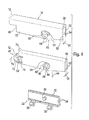
- the wiper arm is provided at its other, free end with a coupling piece 18 ( FIGS. 1 and 4 ), to which the wiper blade 14 can be connected with a joint part 20 via an adapter.
- the joint part 20 is fixedly connected to a support element 22 of the wiper blade 14, which in the embodiment has two in a common plane and spaced apart, dash-dotted lines spring rails 24 ( FIG. 2 ).
- the band-shaped elongated, resilient support element 22 thus formed is curved in its longitudinal direction over its band surfaces 26 and 28 (FIG. FIG. 1 ).
- FIG. 8 clearly visible where the wiper strip 30 is shown by dash-dotted lines.
- the joint part 20 has a longitudinal wall 32, the two opposite longitudinal cheeks 34 form guide surfaces or support walls.
- the longitudinal wall 32 is provided with retaining claws 36 which engage around the mutually remote longitudinal edges of the two spring rails 24 and secure the two spring rails 24 in the required installation position. This can be done by positive and / or non-positive acting means. Further, it is conceivable to weld the joint part 20 in the region of the retaining claws 36 with the spring rails 24. From the longitudinal wall 32 and from the longitudinal cheeks 34 projecting on both sides each a transversely to the longitudinal direction of the longitudinal wall aligned, the wiper blade side hinge means forming pivot pin 38, of which FIG. 4 but only one, at the Viewer facing side facing pivot pin is visible. The axes of the two pivot pin 38 are aligned.
- the adapter 40 has a substantially U-shaped cross section ( FIG. 4 ), whose both walls forming U-legs 42 extend from the U-base 44 from the support member 22.
- the distance between the two U-legs 42 is matched to the thickness of the longitudinal wall 32, that this can be accommodated with little play between the two legs 42 ( FIG. 8 ).
- the two U-legs 42 are provided with open to their free ends edge-open mounting channels or receiving slots 46, which pass over a respective restriction 48 in bearing mounts 50 for the pivot pin 38.
- the coupling piece 18 of the wiper arm 12 also has a U-shaped cross section which is dimensioned so that the guide walls 54 formed on the U-legs 52 of the coupling piece 18 for the wiper blade at a distance 55 from each other are suitably matched to the width 56 of the adapter 40.
- the U-base wall 58 of the coupling piece 18 practically forms a cover for the hinge connection.
- the adapter 40 the playfully free or at least low-play between the U-legs 42 receives the longitudinal wall 32 of the joint part 20 and beyond the facing guide walls 54 on the U-legs 52 of the coupling piece 18, the U-legs 42 also overlap play, This results in an excellent guide for the wiper blade when it is moved transversely to its longitudinal extent on the disc 15 to be wiped.
- a possible play-free guidance of the wiper blade on the wiper arm is desired because such counteracts the Ratterne
- the adapter 40 has at its two facing away from each other outer leg cheeks each have a collar-like projection 60 which surrounds the respective bearing seat 50.
- This collar-like projection 60 increases the bearing surface of the bearing receptacles 50 and also leads to a stabilization of the adapter 40 at least in the area where the receiving slots 46 are arranged for the hinge pin or pivot pin 38 of the joint part 20.
- These two collar-like projections 60 are each assigned an open-edged recess 62 in the guide walls 54 having U-legs 52 of the coupling piece 18.
- the recesses 62 open at the free ends of the U-legs 52.
- the end portions 63 of the recesses 62 are adapted in shape to the contours of the lugs 60.
- the course of the recesses 62 is curved so that their end portions 63 are closer to the pendulum axis 16 of the wiper arm 12 than the mouths 61 at the free ends of the U-legs 52.
- the course of the necessary curvature is designed so that in The edge region of the U-legs 52 each have a securing tongue 64 remains, which extends from the end portion 63 of the recess 62 from the mouth 61 of the recess 62 ( figure 4 ).
- a counter-stop shoulder 66 is formed on the coupling piece 18, which faces the pendulum axis 16.
- This counter-stop shoulder 66 is associated with a stop shoulder 68, which is formed on the adapter 40.
- 40 elastically deflectable extensions or tongues 70 are located on each of the two U-legs 42 of the adapter, on the outer sides of each of which a latching tooth 72 is located.
- At each of the ratchet teeth 72 are the abovementioned stop shoulders 68, which point to the collar-like projections 60 ( FIG. 4 ).
- the adapter 40 of the wiper blade in the direction of the arrow 49 is first applied to the hinge part 20 of the wiper blade 14 for its assembly.
- the constriction 48 in the U-legs 42 of the adapter 40 reach the pivot pin 38 of the joint part 20 via serving as a mounting channel receiving slots 46 in their bearing mounts 50.
- the dimensional adjustment of these components is made such that the adapter to the common axis of the pivot pin 38 is pendelbar within certain limits.
- the tongues 70 extend beyond the longitudinal wall 32 of the articulated part 20, so that they can be moved by overcoming a restoring force essentially transversely to the longitudinal cheeks or surfaces 34 of the longitudinal wall 32 facing away from one another.
- the wiper blade 14 with its adapter 40 is now introduced between the U-legs 52 of the coupling part 18 of the wiper arm 12 serving as a connection part.
- the collar-like projections 60 are introduced via the mouths 61 into the recesses 62 until the collar walls 59 abut against the end regions 63 of the recesses 62.
- the tongues 70 arranged on the walls or on the U-limbs 42 of the adapter 40 are manually deflected toward one another - ie transversely to the surfaces 34 - so that the locking teeth 72 can likewise reach between the U-limbs 52 of the connection part 18 .
- the stop shoulders 68 of the locking teeth 72 pass beyond the counter stop shoulders 66 and spring back into their starting position.
- the stop shoulders 68 hook-like engage behind the counterstop shoulders 66 (FIG. FIGS. 2 and 3 ).
- the wiper blade 14 is now fixed to the wiper arm 12 in its longitudinal direction, because the distance between the end regions 63 and the counter stop shoulders 66 is matched to the distance between the stop shoulders 68 and the collar walls 59.
- the stop shoulders 68 facing areas of the collar walls 59 together with these mutually facing positioning shoulders, which are assigned to each other weg doden counter shoulders - formed by the end portions 63 of the recesses 62 and the counter stop shoulders 66 ( FIG. 2 ).
- the two tongues 70 of the adapter 40 must be deflected towards each other (arrows 74 in FIG. 4 ) until their counter stop shoulders 68 release the stop shoulders 66 of the connector 18. Thereafter, the wiper blade can be pressed towards the free end of the wiper arm until the lugs 60 emerge from the recesses 62, so that the wiper blade 14 is released from the wiper arm.
- the hinge part 20 corresponds to the hinge part described above.
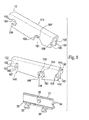
- the adapter 140 has a U-shaped cross-section with U-legs 142, which are provided with open-edge receiving slots 146.
- the constrictions 148 open the receiving slots 146 in bearing mounts 150 for the pivot pin 38 of the joint part 20.
- Collar-like projections 160 surround the bearing receivers 150 and improve the stability of the adapter and the storage of the pivot pin. Deviating from the previously described embodiment of the invention extend in the embodiment according to the FIGS.
- the adapter deflectable tongues 152 of the U-base 144 of the adapter 140 in the direction of the height of the U-legs 142, which represent walls between which dive the formed on the hinge part 20 support walls.
- the tongues 152 are formed by extensions of the U-legs 142.
- a latching tooth 154 is arranged in each case. These ratchet teeth extend from their tongues 152 in opposite directions. They are provided at their the U-base 144 facing top with chamfers 155.
- this has peg-like supports 156 which are arranged on the outer side of each U-leg 142 and which likewise extend away from one another and are each provided with a rounding on their sides facing the collar-like projections 160 , Associated with these curves are recesses 158 serving as support bearings, on the end sides of the U-legs 159 of the U-shaped connecting part 118. Furthermore, the U-legs of the connecting part 118 are provided with collar-like projections 160, which are connected to the free ends of the U-shaped connection part 118. Leg are associated with open-edged recesses 161.
- the recesses 161 each have a shoulder 162 pointing toward the support bearings 158. Relative to the recesses 161, there are provided notches 163 opposite the support bearings 158 in the U-legs 160, which are assigned to the latching teeth 154 of the adapter 140 (FIG. FIG. 5 ).
- the shape of the recesses 161 is adapted at the central region 161 'the course of the collar walls 164.
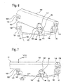
- the adapter 140 When assembling the wiper lever - as already described - first the adapter 140 is pivotally connected to the hinge part 20. Thereafter, according to FIG. 6 the wiper blade with its adapter 140 attached to the connection part 118 of the wiper arm such that the peg-like supports 156 lie in the support bearings 158 ( FIG. 6 ). Thereafter, the wiper blade is pivoted in the direction of the arrow 170 with respect to the wiper arm about a pivot axis of the peg-like supports 156, wherein the collar-like projections dive into their associated recesses 161 in the U-legs 159 of the connection part 118.
- the chamfers 155 of the locking teeth 154 abut against the free ends of the U-legs 159 and are elastically deflected towards each other until they reach the notches 163 in the U-legs 159 after completion of the pivoting movement (arrow 170).
- the ratchet teeth 154 spring back into their original position ( FIGS. 7 and 8th ).
- stop shoulders 167 pointing to the collar-like projections 160 are present on the ratchet teeth 154, which cooperate with counter-stop shoulders 168 of the notches 163 assigned to them.
- the additional shoulders required for the longitudinal locking of the wiper blade on the wiper arm can be formed either by the shoulder 162 and the collar-like projection 160 and / or realized by the peg-like supports 156 and their support bearings 158.
- the locking means are arranged on at least one of the two walls or legs 142 of the adapter 140 and movable substantially transversely to the surfaces of these walls.
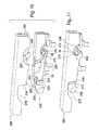
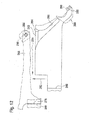
- FIGS. 9 to 12 Another embodiment of the invention is in the FIGS. 9 to 12 shown.
- the joint part 20 of the wiper blade corresponds in terms of the invention completely to the hinge part already described above.
- the adapter 240 corresponds in basic construction to the adapter 40 according to FIG. 4 , So he also has a U-shaped cross-section with U-legs 242 and arranged in the U-legs, to the free ends of open-edge recesses 244 for receiving the pivot pin 38 of the joint part 20.
- the course of the recesses 244 is arranged so that their Mouths 246 are further away from stop shoulders 248 than the bearing receptacles 250 located at the ends of the recesses 244 for the pivot pins 38 of the hinge part 20.
- the recesses 244 are each provided with an elastically expandable constriction 252 Mistake. Furthermore, the recesses 244 have collar-like projections 272 which extend along the entire edge of the respective recess.
- the stop shoulders 248 are tongue-like Extensions 254 of the U-legs 242 arranged and dimensioned so that they extend with stop shoulders 248 over the longitudinal wall 32 of the joint part 20 addition.
- the stop shoulders in each case against a restoring force substantially transversely to the surfaces of the U-legs or walls 242 of the adapter 240 are movable (arrows 287 in FIG. 10 ).
- the tongue-like extension 254 are still each provided with handles 256.
- the adapter 240 has guide slots 260 in the middle area, which extend from the U-base 258 of the U-shaped adapter 240 to the free ends of the U-legs 242.
- a stabilizing web 262 remains between the guide slots 260 in each U-leg 242.
- the course of the guide slots 260 is selected such that they extend from their mouths on the U-base 258 to their sides facing the stop shoulders 248.
- Base an obtuse angle ⁇ ( FIG. 10 ).
- the groove-like guide slots 260 are each provided with a funnel-like widening 264.
- the U-legs 266 of the wiper arm connection part 268 also open-edged recesses 270 for the collar-like projections 272 of the adapter 240, which are open to the free ends of the U-legs 266 down.
- the end portions 274 of these channel-shaped recesses 270 are closer to counter stop shoulders 276, which are formed on the U-legs 266 of the connecting part 268 and point away from the base or end regions 274 of the recesses 270.
- the counter-abutment shoulders 276 are formed on recesses 278 in the U-legs 266 of the connecting part 268.
- guide pins 280 are arranged, which have been formed in the embodiment of the U-legs and pushed inward.
- the diameters of these guide pins 280 are matched to the width of the guide slots 260.
- the adapter 240 When the adapter 240 is to be connected to the hinge part 20, its pivot pins 38 are inserted into their recesses 244 in the U-legs 242 of the adapter 240 until they reach their bearing seats 250 after overcoming the constriction 252 ( FIG. 10 ). Now, the adapter 240 is pendulum but captively connected to the hinge part 20 and for final assembly of the wiper lever 10 ready. For this purpose, the adapter 240 is inserted between the U-legs 266 of the connecting part 268 such that the guide pins 280 pass through the funnel-like extensions 264 into the guide slots 260. This pre-assembly position is in FIG. 12 shown enlarged, wherein the assembly movement is indicated by the arrow 282.
- the wiper blade 14 To release the wiper blade 14 from the wiper arm 12, first the two handles 256 or the tongue-like extensions 254 of the U-legs 242 are pressed together transversely to the wall surfaces present on the outer sides of the U-legs of the adapter (arrows 287, FIGS. FIG. 9 ) that the stop shoulders 248 release the counter stop shoulders 276. Thereafter, the wiper blade can be moved counter to the direction of the arrow 284 (FIG. FIG. 12 ), wherein the guide slots 260 in cooperation with the Guide pin 280 on the connecting part 268 force an arrow 282 opposite disassembly movement.
- each wiper lever or each wiper blade is provided with locking means which are arranged on at least one of the two adapter walls and movable substantially transversely to the surfaces of these walls. Due to the arrangement of the locking devices in the region between the pendulum axis 16 of the wiper arm and the pivot axis of the wiper blade formed by the pivot pin 38, they are located in a lying below the wiper arm 12 level and are thus largely protected against unintentional operation in particular release movement.
Landscapes
- Engineering & Computer Science (AREA)
- Mechanical Engineering (AREA)
- Pivots And Pivotal Connections (AREA)
- Ink Jet (AREA)
- Vehicle Step Arrangements And Article Storage (AREA)
Applications Claiming Priority (6)
| Application Number | Priority Date | Filing Date | Title |
|---|---|---|---|
| DE10214956 | 2002-04-04 | ||
| DE10233531 | 2002-07-23 | ||
| DE10236385 | 2002-08-08 | ||
| DE10243662 | 2002-09-19 | ||
| DE10257988A DE10257988A1 (de) | 2002-04-04 | 2002-12-12 | Wischhebel mit einem Wischerarm und einem an diesem angelenkten Wischblatt |
| EP03722240A EP1494902B1 (fr) | 2002-04-04 | 2003-03-28 | Levier d'essuie-glace muni d'un bras d'essuie-glace et d'un balai d'essuie-glace articule dessus |
Related Parent Applications (1)
| Application Number | Title | Priority Date | Filing Date |
|---|---|---|---|
| EP03722240A Division EP1494902B1 (fr) | 2002-04-04 | 2003-03-28 | Levier d'essuie-glace muni d'un bras d'essuie-glace et d'un balai d'essuie-glace articule dessus |
Publications (1)
| Publication Number | Publication Date |
|---|---|
| EP2025568A1 true EP2025568A1 (fr) | 2009-02-18 |
Family
ID=28457806
Family Applications (1)
| Application Number | Title | Priority Date | Filing Date |
|---|---|---|---|
| EP08105711A Ceased EP2025568A1 (fr) | 2002-04-04 | 2003-03-28 | Dispositif d'essuyage avec un bras d'essuie-glace et un balai connecté au bras |
Country Status (3)
| Country | Link |
|---|---|
| US (2) | US7669276B2 (fr) |
| EP (1) | EP2025568A1 (fr) |
| DE (5) | DE10257991A1 (fr) |
Cited By (1)
| Publication number | Priority date | Publication date | Assignee | Title |
|---|---|---|---|---|
| DE102008033634A1 (de) * | 2008-07-17 | 2010-01-21 | Volkswagen Ag | Anschlussvorrichtung für ein Wischerblatt |
Families Citing this family (63)
| Publication number | Priority date | Publication date | Assignee | Title |
|---|---|---|---|---|
| DE10362341B3 (de) | 2002-11-26 | 2023-02-09 | Valeo Wischersysteme Gmbh | Wischerblatt |
| DE102004007779A1 (de) * | 2004-02-18 | 2005-09-08 | Robert Bosch Gmbh | Wischerarm, für eine Scheibenwischvorrichtung |
| JP4471290B2 (ja) * | 2005-06-03 | 2010-06-02 | 株式会社小糸製作所 | 車輌用灯具の洗浄装置 |
| DE102005053395A1 (de) * | 2005-11-09 | 2007-05-10 | Robert Bosch Gmbh | Gelenkarm aus Kunststoff |
| DE102008000626A1 (de) * | 2008-03-12 | 2009-09-17 | Robert Bosch Gmbh | Vorrichtung zum gelenkigen Verbinden eines Wischblatts |
| DE102008038981A1 (de) * | 2008-08-13 | 2010-02-18 | Volkswagen Ag | Scheibenwischer an einem Fahrzeug |
| DE102008041358A1 (de) * | 2008-08-20 | 2010-02-25 | Robert Bosch Gmbh | Wischblatt, insbesondere zum Wischen von Kraftfahrzeugscheiben |
| US8166604B2 (en) * | 2009-01-30 | 2012-05-01 | Honda Motor Co., Ltd. | Apparatus for preventing unintentional wiper blade removal |
| WO2010142339A1 (fr) * | 2009-06-11 | 2010-12-16 | Federal-Mogul S.A. | Dispositif essuie-glace |
| US9073520B2 (en) * | 2010-07-28 | 2015-07-07 | Teklas Kaucuk Sanayi Ve Ticaret A.S. | Connecting device for windscreen wipers |
| US8495787B2 (en) | 2010-08-03 | 2013-07-30 | Rally Manufacturing, Inc. | Windshield wiper |
| DE112011103091B4 (de) | 2010-09-15 | 2020-10-01 | Trico Products Corporation | Universelles Kopplungselement für eine Windschutzscheibenwischeranordnung vom Typ Balkenblatt |
| USD706200S1 (en) | 2010-09-22 | 2014-06-03 | Pylon Manufacturing Corporation | Windshield wiper cover |
| US20130318735A1 (en) * | 2010-12-02 | 2013-12-05 | Davy Mouth | Windscreen wiper device |
| DE102010062925A1 (de) * | 2010-12-13 | 2012-06-14 | Robert Bosch Gmbh | Wischvorrichtung |
| DE102011004632A1 (de) * | 2011-02-24 | 2012-08-30 | Robert Bosch Gmbh | Wischblatt zum Reinigen von Scheiben insbesondere von Kraftfahrzeugen |
| DE102011001687B4 (de) * | 2011-03-31 | 2025-04-24 | Valeo Systèmes d'Essuyage | Wischblatt zum Reinigen von Fahrzeugscheiben |
| US9174609B2 (en) | 2011-04-21 | 2015-11-03 | Pylon Manufacturing Corp. | Wiper blade with cover |
| US9457768B2 (en) | 2011-04-21 | 2016-10-04 | Pylon Manufacturing Corp. | Vortex damping wiper blade |
| CA2843527C (fr) | 2011-07-28 | 2018-11-27 | Pylon Manufacturing Corp. | Adaptateur, raccord et ensemble d'essuie-glace |
| US8806700B2 (en) | 2011-07-29 | 2014-08-19 | Pylon Manufacturing Corporation | Wiper blade connector |
| US9108595B2 (en) | 2011-07-29 | 2015-08-18 | Pylon Manufacturing Corporation | Windshield wiper connector |
| WO2013019645A1 (fr) | 2011-07-29 | 2013-02-07 | Pylon Manufacturing Corp. | Connecteur d'essuie-glace |
| DE102011053088A1 (de) * | 2011-08-29 | 2013-02-28 | Valeo Wischersysteme Gmbh | Wischblatt für eine Wischeinrichtung eines Kraftfahrzeugs |
| FR2979875B1 (fr) | 2011-09-12 | 2013-09-27 | Valeo Systemes Dessuyage | Adaptateur a languettes flexibles pour systeme d'essuyage |
| FR2979876B1 (fr) | 2011-09-12 | 2013-09-27 | Valeo Systemes Dessuyage | Ensemble de connexion pour systeme d'essuyage d'un vehicule automobile |
| US10723322B2 (en) | 2012-02-24 | 2020-07-28 | Pylon Manufacturing Corp. | Wiper blade with cover |
| MX385411B (es) | 2012-02-24 | 2025-03-18 | Pylon Mfg Corp | Escobilla limpiaparabrisas. |
| US20130219649A1 (en) | 2012-02-24 | 2013-08-29 | Pylon Manufacturing Corp. | Wiper blade |
| DE102012104907B4 (de) * | 2012-06-06 | 2022-08-04 | Valeo Systèmes d'Essuyage | Wischblatt zum Reinigen von Fahrzeugscheiben |
| DE102012011660A1 (de) * | 2012-06-13 | 2013-12-19 | Daimler Ag | Wischblatt, Wischarm und Verbindungsanordnung für eine Scheibenwischanlage eines Fahrzeugs |
| DE102012106947A1 (de) * | 2012-07-30 | 2014-01-30 | Valeo Systèmes d'Essuyage | Wischblatt zum Reinigen von Fahrzeugscheiben |
| US10144393B2 (en) * | 2012-08-13 | 2018-12-04 | Mitsuba Teklas Turkey Otomotiv Anonim Sirketi | Windscreen wiper |
| US10829092B2 (en) | 2012-09-24 | 2020-11-10 | Pylon Manufacturing Corp. | Wiper blade with modular mounting base |
| US10166951B2 (en) | 2013-03-15 | 2019-01-01 | Pylon Manufacturing Corp. | Windshield wiper connector |
| US9555775B2 (en) | 2013-03-15 | 2017-01-31 | Illinois Tool Works Inc. | Connectors and connector kit for attachment of a windshield wiper blade to multiple types of windshield wiper arms |
| US9511748B2 (en) | 2013-03-15 | 2016-12-06 | Illinois Tool Works Inc. | Universal connector for attachment of a windshield wiper blade with multiple types of windshield wiper arms |
| US9616854B2 (en) * | 2013-04-25 | 2017-04-11 | Trico Products Corporation | Mounting assembly for wiper blade and wiper arm |
| DE112014003093B4 (de) | 2013-07-02 | 2020-09-10 | Trico Products Corporation | Universalverbindungsanordnung |
| USD727238S1 (en) | 2013-12-13 | 2015-04-21 | Illinois Tool Works Inc. | Cover used for windshield wiper connectors |
| FR3015397B1 (fr) * | 2013-12-20 | 2017-03-31 | Valeo Systemes Dessuyage | Moyen de support pour un systeme d'essuyage d'une vitre d'un vehicule |
| US9505380B2 (en) | 2014-03-07 | 2016-11-29 | Pylon Manufacturing Corp. | Windshield wiper connector and assembly |
| USD777079S1 (en) | 2014-10-03 | 2017-01-24 | Pylon Manufacturing Corp. | Wiper blade frame |
| USD787308S1 (en) | 2014-10-03 | 2017-05-23 | Pylon Manufacturing Corp. | Wiper blade package |
| ES2579086B1 (es) * | 2015-02-04 | 2017-02-23 | Doga, S. A. | Procedimiento de fabricación de ballestas de limpiaparabrisas y conjunto de terminal de brazo de limpiaparabrisas, de adaptador de escobilla y de acoplamiento |
| CN104890638A (zh) * | 2015-05-13 | 2015-09-09 | 丹阳镇威汽配有限公司 | 用于雨刮片和摇臂之间的固定接头机构 |
| FR3037902B1 (fr) * | 2015-06-29 | 2019-05-10 | Valeo Systemes D'essuyage | Adaptateur pour relier un balai d'essuyage a un bras d'entrainement |
| US10363905B2 (en) | 2015-10-26 | 2019-07-30 | Pylon Manufacturing Corp. | Wiper blade |
| WO2017142971A1 (fr) * | 2016-02-15 | 2017-08-24 | Trico Products Corporation | Adaptateur d'essuie-glace et ensemble d'essuie-glace incorporant celui-ci |
| CN109311452A (zh) | 2016-05-19 | 2019-02-05 | 电缆塔制造有限公司 | 挡风玻璃雨刮器连接器 |
| US11040705B2 (en) | 2016-05-19 | 2021-06-22 | Pylon Manufacturing Corp. | Windshield wiper connector |
| AU2017268008A1 (en) | 2016-05-19 | 2018-11-22 | Pylon Manufacturing Corp. | Windshield wiper connector |
| CN109311450A (zh) | 2016-05-19 | 2019-02-05 | 电缆塔制造有限公司 | 挡风玻璃雨刮器连接器 |
| EP3458315B1 (fr) | 2016-05-19 | 2021-09-08 | Pylon Manufacturing Corp. | Balai d'essuie-glace |
| FR3055861B1 (fr) * | 2016-09-14 | 2019-07-12 | Valeo Systemes D'essuyage | Adaptateur pour la connexion d'un balai d'essuyage a un bras d'entrainement d'un systeme d'essuyage pour vehicule automobile |
| US10150452B2 (en) * | 2016-10-14 | 2018-12-11 | Federal-Mogul Motorparts Llc | Windscreen wiper device |
| FR3066457B1 (fr) | 2017-05-19 | 2019-07-12 | Valeo Systemes D'essuyage | Adaptateur destine a relier un balai d'essuyage a un bras d'entrainement d'un systeme d'essuyage |
| FR3069509B1 (fr) * | 2017-07-31 | 2020-09-04 | Valeo Systemes Dessuyage | Adaptateur perfectionne pour un essuie-glace de vehicule automobile, et ensemble comportant un tel adaptateur |
| FR3069510B1 (fr) * | 2017-07-31 | 2021-03-19 | Valeo Systemes Dessuyage | Adaptateur pour un essuie-glace de vehicule automobile, et ensemble comportant un tel adaptateur |
| FR3089184B1 (fr) * | 2018-12-04 | 2021-06-04 | Valeo Systemes Dessuyage | Adaptateur pour la connexion d'un balai d'essuyage a un bras d'entrainement d'un systeme d'essuyage pour vehicule automobile |
| DE102021101016A1 (de) * | 2021-01-19 | 2022-07-21 | Valeo Wischersysteme Gmbh | Wischblatt und Wischeinrichtung zur Reinigung einer Fahrzeugscheibe sowie Verfahren zur Montage eines Wischblatts |
| CN114670788A (zh) * | 2022-04-19 | 2022-06-28 | 江苏云睿汽车电器系统有限公司 | 一种全新雨刮 |
| EP4717531A1 (fr) * | 2024-09-25 | 2026-04-01 | Doga S.A. | Dispositif d'essuie-glace et balai d'essuie-glace et bras d'essuie-glace correspondants |
Citations (6)
| Publication number | Priority date | Publication date | Assignee | Title |
|---|---|---|---|---|
| DE4224866A1 (de) * | 1992-07-28 | 1994-02-03 | Bosch Gmbh Robert | Vorrichtung zum Wischen von Scheiben von Kraftfahrzeugen |
| DE19860644A1 (de) * | 1998-12-29 | 2000-07-06 | Bosch Gmbh Robert | Vorrichtung zum gelenkigen Verbinden eines Wischblatts für Scheiben von Kraftfahrzeugen mit einem Wischerarm und Verfahren zum Herstellen dieser Verbindung |
| WO2002040328A1 (fr) * | 2000-11-18 | 2002-05-23 | Robert Bosch Gmbh | Dispositif de fixation liberable d'un essuie-glace pour le nettoyage de vitres, en particulier de vehicules a moteur, sur un bras d'essuie-glace |
| DE10065124A1 (de) | 2000-12-28 | 2002-07-04 | Bosch Gmbh Robert | Vorrichtung zum lösbaren Verbinden eines Wischblatts mit einem Wischerarm |
| WO2002053421A1 (fr) * | 2000-12-28 | 2002-07-11 | Robert Bosch Gmbh | Dispositif de fixation amovible d'un balai d'essuie-glace sur un bras d'essuie-glace |
| WO2003080409A1 (fr) * | 2002-03-21 | 2003-10-02 | Valeo Systemes D'essuyage | Dispositif d'essuie-glace comprenant un balai d'essuie-glace plat et un bras d'essuie-glace |
Family Cites Families (16)
| Publication number | Priority date | Publication date | Assignee | Title |
|---|---|---|---|---|
| US3408680A (en) * | 1966-01-28 | 1968-11-05 | Fridon Mfg Ltd | Windshield wiper assemblies |
| US3576044A (en) * | 1968-02-05 | 1971-04-27 | Sev Marchal | Means for attaching the arm of a windshield wiper to the blade support thereof |
| US3757377A (en) * | 1971-10-26 | 1973-09-11 | Tridon Ltd | Windshield wiper clip assemblies |
| US3899800A (en) * | 1974-08-22 | 1975-08-19 | Anderson Co | Windshield wiper blade |
| US4120069A (en) * | 1977-04-20 | 1978-10-17 | Parker-Hannifin Corporation | Adapter for coupling windshield wiper blade holder with hooked wiper arm |
| DE2817248A1 (de) * | 1978-04-20 | 1979-10-31 | Bosch Gmbh Robert | Wischvorrichtung fuer scheiben von kraftfahrzeugen |
| IT1165191B (it) * | 1979-03-30 | 1987-04-22 | Arman Spa | Dispositivo adattatore per collegare una spatola tergicristallo ad attacco dorsale ad un braccio di comando ad attacco laterale |
| US4445249A (en) * | 1982-03-30 | 1984-05-01 | The Anderson Company Of Indiana | Rock-to-lock connection arm-to-blade |
| DE8522252U1 (de) | 1985-08-02 | 1986-11-27 | Robert Bosch Gmbh, 7000 Stuttgart | Wischvorrichtung für Scheiben von Kraftfahrzeugen, insbesondere Abdeckscheiben von Kraftfahrzeugleuchten |
| GB2193432B (en) * | 1986-08-01 | 1990-04-25 | Trico Folberth Ltd | Pivot joint |
| FR2653080B1 (fr) * | 1989-10-13 | 1991-12-06 | Journee Paul Sa | Dispositif connecteur pour balai d'essuie-glace, notamment pour vehicule automobile. |
| JPH0423555U (fr) | 1990-06-21 | 1992-02-26 | ||
| DE4438223A1 (de) | 1994-10-26 | 1996-05-02 | Bosch Gmbh Robert | Wischvorrichtung für Scheiben von Kraftfahrzeugen |
| DE19757872A1 (de) | 1997-12-24 | 1999-07-01 | Bosch Gmbh Robert | Wischvorrichtung für Scheiben von Kraftfahrzeugen mit einem am Kraftfahrzeug geführten pendelnd angetriebenen Wischerarm |
| FR2782043B1 (fr) | 1998-08-07 | 2000-09-15 | Valeo Systemes Dessuyage | Essuie-glace de vehicule automobile comportant des moyens perfectionnes d'articulation et de verrouillage d'un balai d'essuie-glace sur un bras d'essuie-glace |
| JP4087022B2 (ja) | 1999-08-31 | 2008-05-14 | アスモ株式会社 | ワイパブレード |
-
2002
- 2002-12-12 DE DE10257991A patent/DE10257991A1/de not_active Withdrawn
- 2002-12-12 DE DE10257990A patent/DE10257990A1/de not_active Withdrawn
- 2002-12-12 DE DE10257988A patent/DE10257988A1/de not_active Withdrawn
-
2003
- 2003-03-28 DE DE50310515T patent/DE50310515D1/de not_active Expired - Lifetime
- 2003-03-28 EP EP08105711A patent/EP2025568A1/fr not_active Ceased
- 2003-03-28 DE DE50310742T patent/DE50310742D1/de not_active Expired - Lifetime
- 2003-03-28 US US10/509,716 patent/US7669276B2/en not_active Expired - Fee Related
-
2010
- 2010-01-11 US US12/685,447 patent/US8069528B2/en not_active Expired - Fee Related
Patent Citations (6)
| Publication number | Priority date | Publication date | Assignee | Title |
|---|---|---|---|---|
| DE4224866A1 (de) * | 1992-07-28 | 1994-02-03 | Bosch Gmbh Robert | Vorrichtung zum Wischen von Scheiben von Kraftfahrzeugen |
| DE19860644A1 (de) * | 1998-12-29 | 2000-07-06 | Bosch Gmbh Robert | Vorrichtung zum gelenkigen Verbinden eines Wischblatts für Scheiben von Kraftfahrzeugen mit einem Wischerarm und Verfahren zum Herstellen dieser Verbindung |
| WO2002040328A1 (fr) * | 2000-11-18 | 2002-05-23 | Robert Bosch Gmbh | Dispositif de fixation liberable d'un essuie-glace pour le nettoyage de vitres, en particulier de vehicules a moteur, sur un bras d'essuie-glace |
| DE10065124A1 (de) | 2000-12-28 | 2002-07-04 | Bosch Gmbh Robert | Vorrichtung zum lösbaren Verbinden eines Wischblatts mit einem Wischerarm |
| WO2002053421A1 (fr) * | 2000-12-28 | 2002-07-11 | Robert Bosch Gmbh | Dispositif de fixation amovible d'un balai d'essuie-glace sur un bras d'essuie-glace |
| WO2003080409A1 (fr) * | 2002-03-21 | 2003-10-02 | Valeo Systemes D'essuyage | Dispositif d'essuie-glace comprenant un balai d'essuie-glace plat et un bras d'essuie-glace |
Cited By (1)
| Publication number | Priority date | Publication date | Assignee | Title |
|---|---|---|---|---|
| DE102008033634A1 (de) * | 2008-07-17 | 2010-01-21 | Volkswagen Ag | Anschlussvorrichtung für ein Wischerblatt |
Also Published As
| Publication number | Publication date |
|---|---|
| DE10257988A1 (de) | 2004-02-05 |
| US20060064842A1 (en) | 2006-03-30 |
| US20100107354A1 (en) | 2010-05-06 |
| US8069528B2 (en) | 2011-12-06 |
| DE10257991A1 (de) | 2004-02-05 |
| US7669276B2 (en) | 2010-03-02 |
| DE10257990A1 (de) | 2003-10-16 |
| DE50310742D1 (de) | 2008-12-18 |
| DE50310515D1 (de) | 2008-10-30 |
Similar Documents
| Publication | Publication Date | Title |
|---|---|---|
| EP1494902B1 (fr) | Levier d'essuie-glace muni d'un bras d'essuie-glace et d'un balai d'essuie-glace articule dessus | |
| EP2025568A1 (fr) | Dispositif d'essuyage avec un bras d'essuie-glace et un balai connecté au bras | |
| EP2146877B1 (fr) | Dispositif de connexion pour la connexion articulee d'un balai d'essuie-glace a un bras d'essuie-glace | |
| EP1484224B1 (fr) | Élément de raccordement pour une liaison articulée d'un balai d'essuie-glace avec un bras d'essuie-glace | |
| EP1494901B9 (fr) | Levier d'essuie-glace muni d'un bras d'essuie-glace et d'un balai d'essuie-glace articule dessus, pour nettoyer des vitres, en particulier d'automobiles | |
| EP0869886B1 (fr) | Balai d'essuie-glace pour vitres de vehicule | |
| EP0984878A1 (fr) | Systeme d'essuie-glace pour vehicules a moteur, comportant un bras entraine de fa on oscillante et guide au niveau du vehicule | |
| DE10194665B4 (de) | Vorrichtung zum Verbinden eines Wischerarms mit einem Wischblatt, Wischerarm und Wischblatt | |
| EP1071591B1 (fr) | Dispositif pour raccorder de maniere articulee a un bras d'essuie-glace une raclette d'essuie-glace destinee a des vitres de vehicules automobiles | |
| DE19833666B4 (de) | Wischblatt für Scheiben von Kraftfahrzeugen | |
| DE19935860A1 (de) | Wischvorrichtung für Scheiben von Kraftfahrzeugen mit einem zwischen Umkehrlagen bewegbaren, zur Scheibe belasteten Wischerarm | |
| EP1152931A1 (fr) | Dispositif d'essuie-glace pour vehicules | |
| WO2001030623A1 (fr) | Dispositif essuie-glace pour vehicules automobiles | |
| EP1117577A1 (fr) | Dispositif essuie-glace pour les vitres de vehicules a moteur, dote d'un bras d'essuie-glace contraint en direction de la vitre et mobile entre des positions d'inversion de sens | |
| DE19914413A1 (de) | Wischvorrichtung für Scheiben von Kraftfahrzeugen | |
| EP1332074B1 (fr) | Dispositif pour relier de maniere articulee et amovible un balai d'essuie-glace a un bras d'essuie-glace commande | |
| WO2002053421A1 (fr) | Dispositif de fixation amovible d'un balai d'essuie-glace sur un bras d'essuie-glace | |
| DE20321703U1 (de) | Wischhebel mit einem Wischerarm und einem an diesem angelenkten Wischblatt | |
| DE20314551U1 (de) | Wischhebel mit einem einendig angetriebenen Wischerarm, an dessen freien Ende ein an einer Scheibe anlegbares Wischblatt angeordnet ist | |
| DE2352536C3 (de) | Wischvorrichtung für Scheiben, : insbesondere Abdeckscheiben von Kraftfahrzeugleuchten | |
| DE2352536B2 (de) | Wischvorrichtung fuer scheiben, insbesondere abdeckscheiben von kraftfahrzeugleuchten |
Legal Events
| Date | Code | Title | Description |
|---|---|---|---|
| PUAI | Public reference made under article 153(3) epc to a published international application that has entered the european phase |
Free format text: ORIGINAL CODE: 0009012 |
|
| AC | Divisional application: reference to earlier application |
Ref document number: 1494902 Country of ref document: EP Kind code of ref document: P |
|
| AK | Designated contracting states |
Kind code of ref document: A1 Designated state(s): DE FR GB IT |
|
| 17P | Request for examination filed |
Effective date: 20090818 |
|
| 17Q | First examination report despatched |
Effective date: 20090914 |
|
| AKX | Designation fees paid |
Designated state(s): DE FR GB IT |
|
| APBK | Appeal reference recorded |
Free format text: ORIGINAL CODE: EPIDOSNREFNE |
|
| APBN | Date of receipt of notice of appeal recorded |
Free format text: ORIGINAL CODE: EPIDOSNNOA2E |
|
| APBR | Date of receipt of statement of grounds of appeal recorded |
Free format text: ORIGINAL CODE: EPIDOSNNOA3E |
|
| APAF | Appeal reference modified |
Free format text: ORIGINAL CODE: EPIDOSCREFNE |
|
| APBT | Appeal procedure closed |
Free format text: ORIGINAL CODE: EPIDOSNNOA9E |
|
| STAA | Information on the status of an ep patent application or granted ep patent |
Free format text: STATUS: THE APPLICATION HAS BEEN REFUSED |
|
| 18R | Application refused |
Effective date: 20150820 |