EP1495148B1 - Drehmesser zum entfleischen - Google Patents
Drehmesser zum entfleischen Download PDFInfo
- Publication number
- EP1495148B1 EP1495148B1 EP03746311A EP03746311A EP1495148B1 EP 1495148 B1 EP1495148 B1 EP 1495148B1 EP 03746311 A EP03746311 A EP 03746311A EP 03746311 A EP03746311 A EP 03746311A EP 1495148 B1 EP1495148 B1 EP 1495148B1
- Authority
- EP
- European Patent Office
- Prior art keywords
- cutter
- defleshing
- lamellar
- rotary
- insert
- Prior art date
- Legal status (The legal status is an assumption and is not a legal conclusion. Google has not performed a legal analysis and makes no representation as to the accuracy of the status listed.)
- Expired - Lifetime
Links
Images


Classifications
-
- C—CHEMISTRY; METALLURGY
- C14—SKINS; HIDES; PELTS; LEATHER
- C14B—MECHANICAL TREATMENT OR PROCESSING OF SKINS, HIDES OR LEATHER IN GENERAL; PELT-SHEARING MACHINES; INTESTINE-SPLITTING MACHINES
- C14B17/00—Details of apparatus or machines for manufacturing or treating skins, hides, leather, or furs
- C14B17/02—Blading cylinders or other working cylinders, e.g. slicking or scraping cylinders
-
- C—CHEMISTRY; METALLURGY
- C14—SKINS; HIDES; PELTS; LEATHER
- C14B—MECHANICAL TREATMENT OR PROCESSING OF SKINS, HIDES OR LEATHER IN GENERAL; PELT-SHEARING MACHINES; INTESTINE-SPLITTING MACHINES
- C14B1/00—Manufacture of leather; Machines or devices therefor
- C14B1/02—Fleshing, unhairing, samming, stretching-out, setting-out, shaving, splitting, or skiving skins, hides, or leather
- C14B1/04—Fleshing, unhairing, samming, stretching-out, setting-out, shaving, splitting, or skiving skins, hides, or leather using slicking, scraping, or smoothing-out cylinders or blades fixed on supports, e.g. cylinders, in a plane substantially at right angles to the working surface
Definitions
- the present invention relates to a rotary defleshing cutter comprising a central cutter head of a substantially circular or polygonal cross section having its periphery provided with substantially axially aligned grooves adapted to accommodate individually replaceable elastic cutting inserts.
- a rotary defleshing cutter is described in document FI utility model No. 3272 .
- the hide In defleshing of animal hide, the hide is tensioned inside out on substantially conical defleshing drum actuated into a slow-motion rotation.
- a rapidly rotating cutter is adapted to meet the animal hide in such a position that its axis of rotation is situated in a plane perpendicular to the longitudinal axis of the defleshing drum, preferably in a vertical position.
- the cutter is drivent in a slow motion on the defleshing drum from the nose end to the tail end of the animal hide so as to perform the defleshing operation along a helical line.
- the rotation of the defleshing drum and the drive speed of the cutter are synchrohized with each other so that the forward motion of the cutter during one revolution of the defleshing drum corresponds to the width of the area defleshed by the cutter at the same time, where by the entire hide will become defleshed as the cutter reaches the tail end of the hide.
- An example of an apparatus operating according to these principles is described in WO 92/02643 .
- the above problem can be overcome by virtue of a cutter construction offering a sufficiently effective defleshing effect also when driven in a reverse direction of rotation thus allowing the flesh still adhering to the hide under the front-feet and ear portions thereof during back running of the defleshing machine, whereby also the rotating direction of the defleshing cutter is reversed.
- a defleshing cutter of the above-described type having a pair of cutting inserts mounted in a reversed position.
- this pair of cutting inserts performs a certain degree of defleshing when the cutter is driven reverse to its normal rotating direction.
- a shortcoming of such a cutter is that notwithstanding the selected rotating direction, anyhow those cutting inserts that are at any time oriented in the "wrong" direction will contribute negatively to the defleshing effect.
- This goal is attained by virtue of a defleshing cutter characterized in that the cutting inserts and mounting grooves of the cutter are shaped so as to allow a limited inclination of each cutting insert about the longitudinal axis of said insert, while the distal end of cutting insert is provided with two cutting edges running longitudinally along both edges of the distal end of the cutting insert.
- an optimized shaping of the insert and its mouting groove render at all times a desired cutting angle and inclination angle of the inserts irrespective of their rotating direction.
- the longitudinal mounting grooves on the periphery of the cutter head have a substantially keyhole-shaped cross section; on the periphery of the cutter head have a substantially keyhole-shaped cross section, whose inner portion is circularly rounded while its radially distal portion opening at the cutter head periphery is shaped slightly flaring with a width larger than the corresponding thickness of the cutting insert in this portion.
- the insert mounted in the groove respectively, comprises an inner stem part having a circular cross section adapted to fit into the circularly rounded inner portion of the groove, and a distal tip part extending radially outwardly from the insert stem and having a thickness smaller than the width of the flaring slot portion of the mounting groove and is provided at its freely projecting distal end with two cutting edges running longitudinally along the insert tip.
- the insert tip part may have a constant width or, alternatively, be slightly flaring, however, with a flaring angle narrower than the flaring angle of the distal portion of the mounting groove.
- the circularly rounded inner portion of the mounting groove and the periphery of the insert stem form with each other such gliding surfaces that allow the insert to pivot around its longitudinal axis, whereby the walls of the flaring slot portion of the mounting groove serve as back stop surfaces for the tip of the insert thus determining the limit angles of insert inclination in either direction.
- the cross section of the mounting groove comprises a rounded main portion with circularly segmental walls, which main portion is recessed inwardly toward the cutter head center axis under a slot made to the cutter head periphery and has thereunder, still more inwardly radially situated under its circular shape, a key slot of a given width.
- the cross section of the key slot may be either rectangular or have the shape of an annular sector.
- a cutting insert designed insertable into this kind of mounting groove has a stem part of circular cross section that in cooperation with the main portion of the mounting groove forms a sliding bearing supporting the inclination of the cutting insert around its longitudinal axis.
- a key portion projects radially inwardly, said key portion being adapted to cooperate with the key slot of the cutter head groove so as to limit the inclination angle of the cutting insert around its longitudinal axis in the mounting groove, whereby the width of the cutter head key slot and the insert key, respectively, are selected such that a desired cutting angle and inclination angle of the insert are obtained irrespective of the rotating direction of the defleshing cutter.
- each one of the inserts having two cutting edges of which the leading edge in regard to the rotating direction of the cutter is at all times the one actively performing defleshing.
- the distal end of the radially outwardly projecting portion of the insert has a concave cross section resulting in sharper cutting edges, particularly if the insert tip cross section additionally is made outwardly flaring toward the distally projecting insert tip.
- the maximum allowable inclination of an insert about its longitudinal axis from its radially neutral position depends on the design of the insert tip, and particularly on the design of its cutting edges.
- the insert inclination angle is in the range of 10° to 15°.
- the defleshing cutter head comprises a cylindrical, central clamping headstock member with a rigid flange at its one end plus a plurality of identical lamellar cutter members adapted rotatable on the cylindrical headstock center member and having above-described mounting grooves made on their periphery for accommodating the cutter inserts and the rigid flange as well as the lamellar cutter members are provided with mutually interacting elements that allow a given degree of mutual angular displacement between the adjacent lamellar members of the defleshing cutter head as well as between the rigid flange and the closest lamellar member abutting the same.
- the mutual angular displacement between the abutting lamellar members makes it possible during the rotation of the defleshing cutter against the animal hide to shift each cutting insert angularly so that a helical alignment of the cutting inserts along the cutter periphery results.
- the rotation of the cutter in a given direction causes each cutting insert sequentially counted from the rigid flange to become angularly displaced in regard to each other in the reverse direction to the rotation by the differential angle permitted by the limited mutual angular displacement facility provided between each two abutting lamellar cutter members.
- the cutting inserts When the cutter rotation is reversed, the cutting inserts will in a similar fashion become angularly shifted in the opposite direction into new positions along the cutter periphery such that their helical alignment assumes the same lamellar member-to-member differential angles as those of the first helical alignment but now with a reversed handedness of the helical alignment.
- This mutual alignment arrangement of the cutting inserts serves to prevent the defleshed tissue from splashing around during defleshing, particularly as the cutter is arranged to be driven about a substantially vertically aligned axis of rotation having the rigid flange situated upmost. In this position of the cutter, the helical alignment of the cutting inserts force the defleshed tissue to be ejected downward so that the removed tissue can be readily collected into a container included in the defleshing machine construction.
- the mutually cooperating elements permitting a certain mutual angular displacement between any two abutting lamellar cutter members, as well as between the rigid flange and the lamellar cutter member closest adjacent thereto comprise in the first embodiment of the invention at least one guide pin projecting in the axial direction from each one of the lamellar cutter members and, respectively, at least one guide hole made in the rigid flange and each one of the lamellar cutter members at the same radial distance from the central axis of the cutter head as the respective guide pins are located, whereby the guide hole has a diameter larger than the outer diameter of the guide pin and the guide pins have a length so short as to extend only into the hole made in the rigid flange or the closest adjacent abutting lamellar cutter member as seen in the direction of the rigid flange.
- the difference between the diameters of the guide pin and the respective guide hole drilled in the lamellar cutter member allows a certain lamellar member during the rotation thereof in a given direction to rotate in the opposite direction by a differential angle in regard to the closest adjacent abutting lamellar cutter member as compared with the angular position of the rigid flange, whereby the differential angle of the mutual rotation between the members is determined by the difference between the diameters of the guide hole and pin.
- the cutting inserts When the cutter rotation is reversed, the cutting inserts will become angularly shifted in the opposite direction assuming new positions along the cutter periphery such that their helical alignment assumes the same lamellar member-to-member differential angles as those of the first helical alignment but now with a reversed handedness of the helical alignment.
- the mutual tangential displacement between any two adjacently abutting lamellar cutter members can be, e.g., 1 to 2 mm as measured between the cutting inserts along the cutter periphery.
- the mutually cooperating elements that limit the mutual angular rotation between the lamellar cutter members on the cylindrical center member of the cutter headstock supporting the lamellar cutter members comprise a key, which rigidly extends longitudinally on the cylindrical center member over the entire length thereof and has a width linearly flaring toward the rigid flange of the cutter headstock, whereby the key is adapted to cooperate with a key slot made on each one of the lamellar cutter members and having a width slightly wider than the maximum width of the cutter headstock key. Then, the difference between the lamellar member key slot and the headstock key at each lamellar member determines the maximum possible angular displacement of a given lamellar member about its neutral position.
- the key of the central headstock of the cutter can have a constant width, while the lamellar cutter members are machined to have key slots of different widths, whereby the lamellar members are stacked so that the lamellar member having the narrowest key slot is placed closest to the rigid flange of the cutter headstock, whereupon the other lamellar members are stacked on the headstock in a successive order of making the key slots to become the larger the farther the individual lamellar member is from the rigid flange of the headstock.
- the number of cutting inserts on the cutter periphery is advantageously 4 to 12. Preferably, the number of inserts is eight.
- the cutting inserts are angularly displaced at equal distances from each other along the defleshing cutter periphery.
- Defleshing cutters of different shapes can be constructed by way of varying the size of the uniform lamellar cutter members. If lamellar members of equal size are used, a substantially cylindrical cutter is formed. In contrast, stacking lamellar cutter members of linearly decreasing or increasing diameter on the headstock used in the assembly of the cutter results in a conical defleshing cutter and, respectively, the use larger-diameter lamellar members at the ends of the cutter with lamellar elements of a diameter stepwise decreasing toward the cutter middle portion gives an hourglass-shaped cutter having a larger diameter at its ends and a reduced diameter at its middle portion.
- This arrangement results in a defleshing cutter of maximized effective defleshing width that further is augmented by making the cutting inserts moderately elastic.
- the cutting inserts can comply very accurately with the conical shape of the defleshing drum when the cutter moves over the defleshing drum in the defleshing of an animal hide.
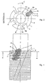
- the defleshing cutter comprises a central cutter head 1 having a substantially circular or polygonal cross section and of a plurality of cutting inserts 2 mounted thereon in substantially axially aligned grooves 3 that are angularly displaced at equal distances from each other along the defleshing cutter periphery.
- the mounting groove 3 has a substantially keyhole-shaped cross section, whose inner portion 3a is circularly rounded while the radially distal portion 3b opening at the cutter head periphery is shaped slightly outwardly flaring.
- the insert 2 mounted in the groove 3 is provided with an inner stem part 2a having a circular cross section adapted to fit into the circularly rounded inner portion of the groove 3, and with a distal tip part 2b extending radially outwardly via the flaring slot portion of the groove and having a thickness smaller than the width of the flaring slot portion 3b of the mounting groove.
- the cutting insert 2 is provided at its freely projecting distal end 2c with two cutting edges 4, 5, both of them running longitudinally along the insert tip. This shape of the mounting groove 3 and of the insert 2 allow the insert 2 to rotate around its longitudinal axis from its one limit position shown in FIG.
- insert distal part 2b By shaping the free end of insert distal part 2b to have a concave cross section (see hatched shape in FIG. 4 ) and by shaping the distal end 2b such that its thickness flares toward its free end 2c, an extremely advantageous shape of both cutting edges 4 and 5 of the insert distal tip is received.
- FIG. 4 is shown an alternative embodiment of the longitudinal mounting groove 3 on the periphery of the cutter head 1 with a cutting insert 2 placed in the groove 3.
- the cross section of the mounting groove 3 comprises a rounded main portion 3a with circularly segmental walls, the main portion being recessed inwardly toward the cutter head center axis under a slot 3b of the periphery of cutter head 1.
- the cutter head 1 is provided with a key slot 3c having a given width and extending still more inwardly radially from the most proximal portion of the above-mentioned rounded mounting groove main portion.
- the cutting insert 2 placed in the mounting groove 3 has a cross section that generally is similar to the cutting insert 2 used in the above-described first embodiment, but differs therefrom by having its stem part 2a complemented with a projection 2d directed in the opposite direction in regard to the distal tip part 2b of the insert.
- the projection 2d fits into the key slot 3c of mounting groove 3 by way of having a width smaller than the width of the key slot 3c.
- the difference between the widths of mounting groove key slot 3c and cutting insert projection 2d is employed to set the angle of inclination that the cutting insert 2 can assume as it is inclined about its longitudinal axis in the mounting groove 3.
- the defleshing cutter comprises an entirely rigid headstock 1, which in the embodiment shown in FIG. 3 is slightly conical.
- the cutter head is connected to the drive shaft of the defleshing machine by the uppermost part of the cutter head in the diagram.
- the cutter head 1 comprises a cylindrical, central clamping member 6 having a rigid flange 7 adapted at its one end.
- a plurality of uniform lamellar members 8 incorporating the above-described mounting grooves for accommodating the cutting inserts 2 of the defleshing cutter.
- the flange 7 and all the lamellar members 8 are provided with a guide hole 9 at a given and same radial distance from the center axis of the cutter head.
- each one of the lamellar members carries an axially projecting guide pin 10 of a diameter smaller than the diameter of the respective guide hole 9, the guide pins 10 being placed at the same radial distance from the center axis of the cutter head as the respective guide holes 9.
- the guide pins 10 project from the side of their respective lamellar member 8 by a length not exceeding the thickness of the adjacent lamellar member 8.
- the first lamellar member 8 is inserted onto the central clamping cylindrical member 6 of the cutter head so that the guide pin 10 of the lamellar member goes into the guide hole 9 of the flange 7.
- the next lamellar member 8 is inserted so that the guide pin of this lamellar member 8 goes into the guide hole 9 of the previously inserted lamellar member as shown in the sectional view of FIG. 1 .
- the mounting grooves 3 on their periphery are initially aligned along axially straight lines on the periphery of the defleshing cutter.
- the cutter is driven to rotate in the direction indicated by arrow C, whereby as a result each lamellar member 8 becomes angularly shifted in a reverse direction in regard to the next adjacent lamellar member 8 closer to the rigid flange 7 by an angle permitted by the difference between the diameters of guide hole 9 and guide pin 10.
- the lamellar members 8 rotate into positions such that the mounting grooves 3 on the periphery of the defleshing cutter align into helical lines as shown in FIG. 1 wherein a complete track of adjacent mounting grooves 3 is shown entirely.
- the cutting inserts 2 placed in the mounting grooves 3 respectively align themselves helically into positions wherein defleshing takes place in a fashion preventing the removed tissue from splashing around and instead the tissue is forced downward toward the lower end of the cutter wherefrom the tissue falls down into a container (not shown).
- the guide pins 10 and guide holes 9 of the lamellar members 8 are replaced by a key 10' which rigidly extends longitudinally on the cylindrical center member 6 of the cutter over the entire length of the center member and has a width linearly flaring toward the rigid flange 7, whereby the key 10' is adapted to cooperate with a key slot 9' made on each one of the lamellar cutter members 8 and having a width slightly wider than the maximum width of the cutter headstock key 10'. Then, at each lamellar member 8, the width difference between the lamellar member key slot 9' and the cutter headstock key 10' determines the maximum possible angular displacement of a given lamellar member 8 about its neutral position on the cutter center member 6.
Landscapes
- Engineering & Computer Science (AREA)
- Manufacturing & Machinery (AREA)
- Mechanical Engineering (AREA)
- Chemical & Material Sciences (AREA)
- Organic Chemistry (AREA)
- Food-Manufacturing Devices (AREA)
- Forging (AREA)
- Electrochromic Elements, Electrophoresis, Or Variable Reflection Or Absorption Elements (AREA)
- Position Input By Displaying (AREA)
- Crushing And Pulverization Processes (AREA)
- Lubricants (AREA)
- Knives (AREA)
- Harvester Elements (AREA)
- Fire-Extinguishing Compositions (AREA)
- Cleaning Or Drying Semiconductors (AREA)
- Crushing And Grinding (AREA)
- Cleaning In General (AREA)
Claims (14)
- Drehbares Entfleischungsmesser, umfassend einen zentralen, im Querschnitt im wesentlichen kreisförmigen oder mehreckigen Messerkörper (1), der an seinem Umfang mit im wesentlichen axial ausgerichteten Halterungsnuten (3) versehen ist, von denen jede zur Aufnahme eines gesondert einsetzbaren elastischen Schneideeinsatzes (2) ausgebildet ist, dadurch gekennzeichnet, dass die Schneideeinsätze (2) und die Halterungsnuten (3) so ausgebildet sind, dass sie eine beschränkte Neigung jedes Schneideeinsatzes (2) um dessen Längsachse ermöglichen, während das Distalende des Schneideeinsatzes (2) mit zwei in Längsrichtung entlang der beiden Kanten des Distalendes des Schneideeinsatzes verlaufenden Schneidekanten (4,5) versehen ist.
- Drehbares Entfleischungsmesser nach Anspruch 1, dadurch gekennzeichnet, dass die am Umfang des Schneidekörpers (1) zur Aufnahme der Schneideeinsätze (2) angeordneten Halterungsnuten (3) einen im wesentlichen Schlüssellochförmigen Querschnitt aufweisen, dessen innerer Abschnitt (3a) kreisförmig ausgebildet ist, während dessen radial in den Umfang des Messerkörpers (1) mündender, sich leicht ausbreitender Distalabschnitt (3b) eine Breite aufweist, die größer ist als die entsprechende Dicke des jeweiligen Schneideeinsatzes (2) in diesem Abschnitt.
- Drehbares Entfleischungsmesser nach Anspruch 2, dadurch gekennzeichnet, dass die Schneideeinsätze (2) im Querschnitt ein inneres, im Querschnitt kreisförmiges, zur Aufnahme in den kreisförmigen inneren Abschnitt (3a) der Halterungsnut (2) ausgebildetes Grundteil (2a) sowie eine sich radial von dem Grundteil erstreckende Distalspitze (2b), deren Dicke kleiner ist als die Breite des sich erweiternden Schlitzabschnitts (3b) der Halterungsnut, aufweisen, wobei die in Längsrichtung entlang der Spitze des Einsatzteils verlaufenden Kanten an den frei vorstehenden Distalende Spitze des Einsatzteils die zwei Schneidekanten (4,5) des Schneideeinsatzes bilden.
- Drehbares Entfleischungsmesser nach Anspruch 1, dadurch gekennzeichnet, dass die am Umfang des Messerkörpers (1) zur Aufnahme der Schneideeinsätze (2) angeordneten Halterungsnuten (3) im Querschnitt einen mit kreisrunden Segmentwänden versehenen kreisförmigen Hauptabschnitt (3a) aufweisen, wobei der Hauptabschnitt (3a) unterhalb der am Umfang des Messerkörpers (1) befindlichen Öffnung (3b) nach innen in Richtung auf die Mittelachse des Messerkörpers (1) ausgehöhlt ist und ferner mit einer Schlüsselaussparung (3c), die eine vorgegebene Breite in Richtung auf die Mitte des Messerkörpers (1) aufweist, versehen ist.
- Drehbares Entfleischungsmesser nach Anspruch 4, dadurch gekennzeichnet, dass der Schneideeinsatz (2) im Querschnitt mit einem kreisförmigen Grundteil (2a), das zur Aufnahme in den Hauptabschnitt (3a) der Halterungsnut ausgebildet ist, und einer von dem besagten Grundteil vorstehenden Distalspitze (2b), deren Breite etwas schmaler ist als die Breite der am Umfang des Messerkörpers (1) befindlichen Öffnung (3b) der Halterungsnut, und die an deren frei vorstehenem Distalende in Längsrichtung verlaufenden Kanten zwei Schneidekanten (4,5) des Schneideeinsatzes bilden, sowie einem sich von dem Grundteil (2a) bezüglich der Distalspitze des Einsatzes in die entgegengesetzte Richtung erstreckenden Vorsprung (2d), deren Breite etwas kleiner ist als die Breite der in der Halterungsnut (3) des Messerkörpers befindlichen Schlüsselaussparung (3c), versehen ist.
- Drehbares Entfleischungsmesser nach einem der vorangehenden Ansprüche, dadurch gekennzeichnet, dass die Schneideeinsätze (2) im Querschnitt eine konkave Außenkontur (2c) der Distalspitze aufweisen.
- Drehbares Entfleischungsmesser nach einem der Ansprüche 1-6, dadurch gekennzeichnet, dass die maximale Neigung der Schneideeinsätze (2) um ihre Längsachse in beide Richtungen von ihrer radialen Grundposition ca. 10 bis 15° beträgt.
- Drehbares Entfleischungsmesser nach einem der Ansprüche 1-7, dadurch gekennzeichnet, dass der Körper (1) des Entfleichungsmessers aus einem zylinderförmigen, zentralen, an einem Ende mit einem feststehenden Flansch (7) versehenen Halterungselement (6) und einer Vielzahl von auf dem besagten zylinderförmigen Element (6) frei drehbar angeordneten gleichförmigen lamellenartigen Schneideelementen (8), die mit den besagten Halterungsnuten (3) zur Aufnahme der Schneideeinsätze versehen sind, besteht, und dass der feststehende Flansch (7) und die lamellenartigen Schneideelementen (8) miteinander in Zusammenwirkung stehende Elemente (9, 10; 9', 10') aufweisen, die eine vorgegebene Verstellung zwischen den einzelnen benachbarten Lamellen (8) des Entfleischungsmesserkörpers sowie zwischen dem feststehenden Flansch (7) und dem diesem am nächsten benachbarten lamellenartigen Element (8) ermöglichen.
- Drehbares Entfleischungsmesser nach Anspruch 8, dadurch gekennzeichnet, dass die miteinander in Zusammenwirkung stehenden Elemente wenigstens einen von jedem lamellenartigen Schneideelement (8) axial vorstehenden Führungsstift (10) sowie wenigstens ein in dem feststehenden Flansch (7) und in jeder lamellenartigen Element (8) gebildetes Führungsloch (8) aufweisen, wobei jedes Führungsloch sich in demselben radialen Abstand von der Mittelachse des Messerkörpers wie der Führungsstift (10) befindet, wobei der Durchmesser des Führungsloches (9) größer ist als der Durchmesser des Führungsstiftes (10), und die Führungsstifte (10) eine solche Länge aufweisen, dass sie nur in das in dem feststehenden Flansch (7) befindliche Führungsloch (9) oder in das in Richtung des feststehenden Flansches (7) am nächsten benachbarten lamellenartigen Schneideelement (8) befindliche Führungsloch (9) eindringen können.
- Drehbares Entfleischungsmesser nach Anspruch 8 oder 9, dadurch gekennzeichnet, dass die schräge Vestellung zwischen jeweils zwei benachbarten lamellenartigen Schneideelementen (8) einer Verstellung von ca. 1 bis 2 mm entlang des Umfangs der lamellenartigen Schneideelementen entspricht.
- Drehbares Entfleischungsmesser nach Anspruch 8, dadurch gekennzeichnet, dass die miteinander in Zusammenwirkung stehenden Elemente zur Beschränkung der schrägen Neigung zwischen jeweils zwei lamellenartigen Elementen (8) um das zentrale Halterungselement (6) des Messerkörpers mit einem Keil (10'), der sich auf dem besagten Element (6) steif in der Längsrichtung erstreckt und eine Breite aufweist, die sich linear in Richtung auf das feststehende Flansch (7) ausweitet, sowie mit einem an jedem lamellenartigen Schneideelement (8) zur Zusammenwirkung mit dem Keil (10') gebildeten Keilschlitz (9'), dessen Breite etwas größer ist als die maximale Breite des Keils (10'), versehen sind.
- Drehbares Entfleischungsmesser nach Anspruch 1, dadurch gekennzeichnet, dass die Anzahl der Schneideeinsätze (2) 4 bis 12 beträgt.
- Drehbares Entfleischungsmesser nach einem der Ansprüche 8-12, dadurch gekennzeichnet, dass alle lamellenartigen Elemente (8) des Messerkörpers der Größe nach identisch sind.
- Drehbares Entfleischungsmesser nach einem der Ansprüche 8-12, dadurch gekennzeichnet, dass die lamellenartigen Elemente (8) des Messerkörpers der Größe nach verschieden sind, so dass der Messerkörper eine konische Form, oder alternativ die Form einer Sanduhr, die in seinem Mittelteil schmaler ist, bekommt.
Applications Claiming Priority (3)
| Application Number | Priority Date | Filing Date | Title |
|---|---|---|---|
| FI20020709A FI114319B (fi) | 2002-04-12 | 2002-04-12 | Pyöritettävä kaapimisterä |
| FI20020709 | 2002-04-12 | ||
| PCT/FI2003/000275 WO2003087413A1 (en) | 2002-04-12 | 2003-04-11 | Rotary defleshing cutter |
Publications (2)
| Publication Number | Publication Date |
|---|---|
| EP1495148A1 EP1495148A1 (de) | 2005-01-12 |
| EP1495148B1 true EP1495148B1 (de) | 2009-03-11 |
Family
ID=8563753
Family Applications (1)
| Application Number | Title | Priority Date | Filing Date |
|---|---|---|---|
| EP03746311A Expired - Lifetime EP1495148B1 (de) | 2002-04-12 | 2003-04-11 | Drehmesser zum entfleischen |
Country Status (7)
| Country | Link |
|---|---|
| EP (1) | EP1495148B1 (de) |
| AT (1) | ATE425268T1 (de) |
| AU (1) | AU2003226844A1 (de) |
| DE (1) | DE60326552D1 (de) |
| DK (1) | DK176616B1 (de) |
| FI (1) | FI114319B (de) |
| WO (1) | WO2003087413A1 (de) |
Families Citing this family (1)
| Publication number | Priority date | Publication date | Assignee | Title |
|---|---|---|---|---|
| DK179245B1 (en) | 2017-03-28 | 2018-03-05 | Fur Tech Aps | Scraping Roller |
Family Cites Families (6)
| Publication number | Priority date | Publication date | Assignee | Title |
|---|---|---|---|---|
| CH152023A (de) * | 1930-10-16 | 1932-01-15 | Rud Dienes Karl | Aus Stahlblech gepresstes, fräserartiges Bearbeitungswerkzeug. |
| GB707891A (en) * | 1950-02-20 | 1954-04-28 | Tanners Res Corp | Improvements in skin treating apparatus |
| DE939948C (de) * | 1954-02-06 | 1956-03-08 | Schumacher & Co | Falz-, Blanchier- oder Entfleischmesser fuer Leder |
| FI67877C (fi) * | 1983-07-04 | 1985-06-10 | Knut Ingvald Oesterberg | Skrapa till skrapmaskin foer skinn |
| DK78286D0 (da) * | 1986-02-20 | 1986-02-20 | Bent Juul Larsen | Apparat til fjernelse af fedtlag fra pelshuders koedside |
| DK173202B1 (da) * | 1990-08-09 | 2000-03-13 | Jasopan V Kamma Jensen | Skrabemaskine |
-
2002
- 2002-04-12 FI FI20020709A patent/FI114319B/fi not_active IP Right Cessation
-
2003
- 2003-03-04 DK DK200300333A patent/DK176616B1/da not_active IP Right Cessation
- 2003-04-11 AT AT03746311T patent/ATE425268T1/de not_active IP Right Cessation
- 2003-04-11 AU AU2003226844A patent/AU2003226844A1/en not_active Abandoned
- 2003-04-11 WO PCT/FI2003/000275 patent/WO2003087413A1/en not_active Ceased
- 2003-04-11 DE DE60326552T patent/DE60326552D1/de not_active Expired - Fee Related
- 2003-04-11 EP EP03746311A patent/EP1495148B1/de not_active Expired - Lifetime
Also Published As
| Publication number | Publication date |
|---|---|
| ATE425268T1 (de) | 2009-03-15 |
| WO2003087413A1 (en) | 2003-10-23 |
| FI114319B (fi) | 2004-09-30 |
| AU2003226844A1 (en) | 2003-10-27 |
| EP1495148A1 (de) | 2005-01-12 |
| DK176616B1 (da) | 2008-11-24 |
| FI20020709A0 (fi) | 2002-04-12 |
| DE60326552D1 (de) | 2009-04-23 |
| DK200300333A (da) | 2003-10-13 |
| FI20020709A7 (fi) | 2003-10-13 |
Similar Documents
| Publication | Publication Date | Title |
|---|---|---|
| US5007917A (en) | Single blade cutter for arthroscopic surgery | |
| US8568432B2 (en) | Catheter for aspirating, fragmenting and removing extractable material from blood vessels | |
| CN102448388B (zh) | 外科手术器械 | |
| US6245074B1 (en) | Orthopaedic glenoid reamer | |
| KR950011666B1 (ko) | 호울 소우(Hole-Saw) | |
| EP1403012A3 (de) | Kreismesser | |
| US20090031567A1 (en) | Fixed line trimmer head with ease of loading | |
| AU5105698A (en) | Eccentric rotational atherectomy device | |
| KR101735139B1 (ko) | 밀링 커터 | |
| DK147729B (da) | Skaeresaet for koedhakkemaskine | |
| US8468921B2 (en) | Brush cylinder | |
| EP2818033B1 (de) | Schneider und rotierender Haltekopf | |
| DK1219163T3 (da) | Snitteindretning | |
| EP0984849B1 (de) | Rasiergerät | |
| GB2207381A (en) | Transverse cutting device for travelling strip | |
| US8161773B2 (en) | Chip breakers for orthopaedic reamers | |
| EP1495148A1 (de) | Drehmesser zum entfleischen | |
| EP0198221A1 (de) | Vorrichtung zum Zerteilen eines endlosen Bandes aus Wickelmaterial in aufeinanderfolgende Einzelabschnitte | |
| US20210114241A1 (en) | External cutting member of a shaving device having hair-guiding elements with thickness profile | |
| KR20210033337A (ko) | 예초기 칼날 | |
| CN118078396A (zh) | 一种切割球囊导管 | |
| JPH10243734A (ja) | ディスク型カッターにおける排稈処理装置 | |
| ATE294642T1 (de) | Zweikammer-schleudermühle | |
| US11273568B2 (en) | Impeller, centrifugal cutting apparatus comprising same, and method of operating same | |
| KR101942909B1 (ko) | 근채류 탈피장치 |
Legal Events
| Date | Code | Title | Description |
|---|---|---|---|
| PUAI | Public reference made under article 153(3) epc to a published international application that has entered the european phase |
Free format text: ORIGINAL CODE: 0009012 |
|
| 17P | Request for examination filed |
Effective date: 20041007 |
|
| AK | Designated contracting states |
Kind code of ref document: A1 Designated state(s): AT BE BG CH CY CZ DE DK EE ES FI FR GB GR HU IE IT LI LU MC NL PT RO SE SI SK TR |
|
| AX | Request for extension of the european patent |
Extension state: AL LT LV MK |
|
| 17Q | First examination report despatched |
Effective date: 20061116 |
|
| GRAP | Despatch of communication of intention to grant a patent |
Free format text: ORIGINAL CODE: EPIDOSNIGR1 |
|
| GRAS | Grant fee paid |
Free format text: ORIGINAL CODE: EPIDOSNIGR3 |
|
| GRAA | (expected) grant |
Free format text: ORIGINAL CODE: 0009210 |
|
| AK | Designated contracting states |
Kind code of ref document: B1 Designated state(s): AT BE BG CH CY CZ DE DK EE ES FI FR GB GR HU IE IT LI LU MC NL PT RO SE SI SK TR |
|
| REG | Reference to a national code |
Ref country code: GB Ref legal event code: FG4D |
|
| REG | Reference to a national code |
Ref country code: CH Ref legal event code: EP |
|
| REG | Reference to a national code |
Ref country code: IE Ref legal event code: FG4D |
|
| REF | Corresponds to: |
Ref document number: 60326552 Country of ref document: DE Date of ref document: 20090423 Kind code of ref document: P |
|
| PG25 | Lapsed in a contracting state [announced via postgrant information from national office to epo] |
Ref country code: SI Free format text: LAPSE BECAUSE OF FAILURE TO SUBMIT A TRANSLATION OF THE DESCRIPTION OR TO PAY THE FEE WITHIN THE PRESCRIBED TIME-LIMIT Effective date: 20090311 Ref country code: NL Free format text: LAPSE BECAUSE OF FAILURE TO SUBMIT A TRANSLATION OF THE DESCRIPTION OR TO PAY THE FEE WITHIN THE PRESCRIBED TIME-LIMIT Effective date: 20090311 Ref country code: FI Free format text: LAPSE BECAUSE OF FAILURE TO SUBMIT A TRANSLATION OF THE DESCRIPTION OR TO PAY THE FEE WITHIN THE PRESCRIBED TIME-LIMIT Effective date: 20090311 |
|
| NLV1 | Nl: lapsed or annulled due to failure to fulfill the requirements of art. 29p and 29m of the patents act | ||
| PG25 | Lapsed in a contracting state [announced via postgrant information from national office to epo] |
Ref country code: SE Free format text: LAPSE BECAUSE OF FAILURE TO SUBMIT A TRANSLATION OF THE DESCRIPTION OR TO PAY THE FEE WITHIN THE PRESCRIBED TIME-LIMIT Effective date: 20090611 Ref country code: AT Free format text: LAPSE BECAUSE OF FAILURE TO SUBMIT A TRANSLATION OF THE DESCRIPTION OR TO PAY THE FEE WITHIN THE PRESCRIBED TIME-LIMIT Effective date: 20090311 |
|
| PG25 | Lapsed in a contracting state [announced via postgrant information from national office to epo] |
Ref country code: BE Free format text: LAPSE BECAUSE OF FAILURE TO SUBMIT A TRANSLATION OF THE DESCRIPTION OR TO PAY THE FEE WITHIN THE PRESCRIBED TIME-LIMIT Effective date: 20090311 |
|
| PG25 | Lapsed in a contracting state [announced via postgrant information from national office to epo] |
Ref country code: CZ Free format text: LAPSE BECAUSE OF FAILURE TO SUBMIT A TRANSLATION OF THE DESCRIPTION OR TO PAY THE FEE WITHIN THE PRESCRIBED TIME-LIMIT Effective date: 20090311 Ref country code: ES Free format text: LAPSE BECAUSE OF FAILURE TO SUBMIT A TRANSLATION OF THE DESCRIPTION OR TO PAY THE FEE WITHIN THE PRESCRIBED TIME-LIMIT Effective date: 20090622 Ref country code: PT Free format text: LAPSE BECAUSE OF FAILURE TO SUBMIT A TRANSLATION OF THE DESCRIPTION OR TO PAY THE FEE WITHIN THE PRESCRIBED TIME-LIMIT Effective date: 20090824 Ref country code: EE Free format text: LAPSE BECAUSE OF FAILURE TO SUBMIT A TRANSLATION OF THE DESCRIPTION OR TO PAY THE FEE WITHIN THE PRESCRIBED TIME-LIMIT Effective date: 20090311 |
|
| PG25 | Lapsed in a contracting state [announced via postgrant information from national office to epo] |
Ref country code: RO Free format text: LAPSE BECAUSE OF FAILURE TO SUBMIT A TRANSLATION OF THE DESCRIPTION OR TO PAY THE FEE WITHIN THE PRESCRIBED TIME-LIMIT Effective date: 20090311 Ref country code: SK Free format text: LAPSE BECAUSE OF FAILURE TO SUBMIT A TRANSLATION OF THE DESCRIPTION OR TO PAY THE FEE WITHIN THE PRESCRIBED TIME-LIMIT Effective date: 20090311 |
|
| REG | Reference to a national code |
Ref country code: CH Ref legal event code: PL |
|
| PLBE | No opposition filed within time limit |
Free format text: ORIGINAL CODE: 0009261 |
|
| STAA | Information on the status of an ep patent application or granted ep patent |
Free format text: STATUS: NO OPPOSITION FILED WITHIN TIME LIMIT |
|
| REG | Reference to a national code |
Ref country code: FR Ref legal event code: ST Effective date: 20091231 |
|
| PG25 | Lapsed in a contracting state [announced via postgrant information from national office to epo] |
Ref country code: CH Free format text: LAPSE BECAUSE OF NON-PAYMENT OF DUE FEES Effective date: 20090430 Ref country code: LI Free format text: LAPSE BECAUSE OF NON-PAYMENT OF DUE FEES Effective date: 20090430 Ref country code: DK Free format text: LAPSE BECAUSE OF FAILURE TO SUBMIT A TRANSLATION OF THE DESCRIPTION OR TO PAY THE FEE WITHIN THE PRESCRIBED TIME-LIMIT Effective date: 20090311 Ref country code: BG Free format text: LAPSE BECAUSE OF FAILURE TO SUBMIT A TRANSLATION OF THE DESCRIPTION OR TO PAY THE FEE WITHIN THE PRESCRIBED TIME-LIMIT Effective date: 20090611 Ref country code: DE Free format text: LAPSE BECAUSE OF NON-PAYMENT OF DUE FEES Effective date: 20091103 |
|
| REG | Reference to a national code |
Ref country code: IE Ref legal event code: MM4A |
|
| 26N | No opposition filed |
Effective date: 20091214 |
|
| GBPC | Gb: european patent ceased through non-payment of renewal fee |
Effective date: 20090611 |
|
| PG25 | Lapsed in a contracting state [announced via postgrant information from national office to epo] |
Ref country code: MC Free format text: LAPSE BECAUSE OF NON-PAYMENT OF DUE FEES Effective date: 20090430 Ref country code: FR Free format text: LAPSE BECAUSE OF NON-PAYMENT OF DUE FEES Effective date: 20091222 Ref country code: IE Free format text: LAPSE BECAUSE OF NON-PAYMENT OF DUE FEES Effective date: 20090411 |
|
| PG25 | Lapsed in a contracting state [announced via postgrant information from national office to epo] |
Ref country code: GB Free format text: LAPSE BECAUSE OF NON-PAYMENT OF DUE FEES Effective date: 20090611 |
|
| PG25 | Lapsed in a contracting state [announced via postgrant information from national office to epo] |
Ref country code: GR Free format text: LAPSE BECAUSE OF FAILURE TO SUBMIT A TRANSLATION OF THE DESCRIPTION OR TO PAY THE FEE WITHIN THE PRESCRIBED TIME-LIMIT Effective date: 20090612 |
|
| PG25 | Lapsed in a contracting state [announced via postgrant information from national office to epo] |
Ref country code: IT Free format text: LAPSE BECAUSE OF FAILURE TO SUBMIT A TRANSLATION OF THE DESCRIPTION OR TO PAY THE FEE WITHIN THE PRESCRIBED TIME-LIMIT Effective date: 20090311 |
|
| PG25 | Lapsed in a contracting state [announced via postgrant information from national office to epo] |
Ref country code: LU Free format text: LAPSE BECAUSE OF NON-PAYMENT OF DUE FEES Effective date: 20090411 |
|
| PG25 | Lapsed in a contracting state [announced via postgrant information from national office to epo] |
Ref country code: HU Free format text: LAPSE BECAUSE OF FAILURE TO SUBMIT A TRANSLATION OF THE DESCRIPTION OR TO PAY THE FEE WITHIN THE PRESCRIBED TIME-LIMIT Effective date: 20090912 |
|
| PG25 | Lapsed in a contracting state [announced via postgrant information from national office to epo] |
Ref country code: TR Free format text: LAPSE BECAUSE OF FAILURE TO SUBMIT A TRANSLATION OF THE DESCRIPTION OR TO PAY THE FEE WITHIN THE PRESCRIBED TIME-LIMIT Effective date: 20090311 |
|
| PG25 | Lapsed in a contracting state [announced via postgrant information from national office to epo] |
Ref country code: CY Free format text: LAPSE BECAUSE OF FAILURE TO SUBMIT A TRANSLATION OF THE DESCRIPTION OR TO PAY THE FEE WITHIN THE PRESCRIBED TIME-LIMIT Effective date: 20090311 |