EP1495943B1 - Aktuator für Lenkgetriebe - Google Patents
Aktuator für Lenkgetriebe Download PDFInfo
- Publication number
- EP1495943B1 EP1495943B1 EP20040016050 EP04016050A EP1495943B1 EP 1495943 B1 EP1495943 B1 EP 1495943B1 EP 20040016050 EP20040016050 EP 20040016050 EP 04016050 A EP04016050 A EP 04016050A EP 1495943 B1 EP1495943 B1 EP 1495943B1
- Authority
- EP
- European Patent Office
- Prior art keywords
- actuator
- driving
- screw
- gear
- hydraulic servo
- Prior art date
- Legal status (The legal status is an assumption and is not a legal conclusion. Google has not performed a legal analysis and makes no representation as to the accuracy of the status listed.)
- Expired - Lifetime
Links
- 230000033001 locomotion Effects 0.000 claims description 23
- 230000005540 biological transmission Effects 0.000 claims description 3
- 230000002146 bilateral effect Effects 0.000 claims 1
- 230000003134 recirculating effect Effects 0.000 claims 1
- 230000001131 transforming effect Effects 0.000 description 2
- 230000008878 coupling Effects 0.000 description 1
- 238000010168 coupling process Methods 0.000 description 1
- 238000005859 coupling reaction Methods 0.000 description 1
- 230000001419 dependent effect Effects 0.000 description 1
- 230000000694 effects Effects 0.000 description 1
Images
Classifications
-
- B—PERFORMING OPERATIONS; TRANSPORTING
- B62—LAND VEHICLES FOR TRAVELLING OTHERWISE THAN ON RAILS
- B62D—MOTOR VEHICLES; TRAILERS
- B62D5/00—Power-assisted or power-driven steering
- B62D5/06—Power-assisted or power-driven steering fluid, i.e. using a pressurised fluid for most or all the force required for steering a vehicle
- B62D5/09—Power-assisted or power-driven steering fluid, i.e. using a pressurised fluid for most or all the force required for steering a vehicle characterised by means for actuating valves
- B62D5/091—Hydraulic steer-by-wire systems, e.g. the valve being actuated by an electric motor
- B62D5/092—Hydraulic steer-by-wire systems, e.g. the valve being actuated by an electric motor the electric motor being connected to the final driven element of the steering gear, e.g. rack
-
- B—PERFORMING OPERATIONS; TRANSPORTING
- B62—LAND VEHICLES FOR TRAVELLING OTHERWISE THAN ON RAILS
- B62D—MOTOR VEHICLES; TRAILERS
- B62D5/00—Power-assisted or power-driven steering
- B62D5/04—Power-assisted or power-driven steering electrical, e.g. using an electric servo-motor connected to, or forming part of, the steering gear
- B62D5/0442—Conversion of rotational into longitudinal movement
- B62D5/0445—Screw drives
- B62D5/0448—Ball nuts
Definitions
- the invention relates to an actuator, in particular a Radaktuator for a steer-by-wire steering system of a vehicle according to the preamble of claim 1.
- DE 195 41 749 C1 describes an actuator for a steering system in which the mechanical forced coupling between a steering handle and steered wheels of a vehicle is canceled.
- a preferably designed as an electric motor servomotor is controlled by a control device.
- the servo motor is used to control a control valve of a servo cylinder for steering adjustment of steered wheels and also acts directly on a trained as a rack and pinion steering gear.
- the actuator thus always has two outputs and is linked to a steering gear.
- DE 100 60 832 A 1 describes an actuator of a power steering system according to the steer-by-wire principle, with an electric motor for driving a hydraulic control valve for a servo cylinder of the actuator.
- the electric motor is dimensioned so that it can handle the adjusting movement via a reduction gear, which represents the torque train via the hydraulic control valve to a motion screw, in case of failure of the servo cylinder alone.
- the actuator acts on the steered wheels via an output. Its space is not minimized due to the single-stage reduction gear. In addition, the actuator is less suitable for steering systems of heavy vehicles.
- the invention has for its object to provide an actuator which is suitable for steering systems heavy cars and commercial vehicles with minimal space requirements.
- a reduction gear forms the torque train between the electric motor and the output of the actuator, which is at least two stages, a narrow design of the actuator and a high gear ratio is provided to represent large output actuating forces.
- An idler gear of the reduction gear which is preferably driven by a wheel or pinion of the electric motor, is rotatably connected to a rotary valve of the hydraulic control valve.
- the rotary valve of the hydraulic control valve is rotatably operatively connected via a torsion element, preferably via a torsion bar, with a control bush of the hydraulic control valve.
- a wheel on the control sleeve drives the axially immovable, a rotary motion in a translational motion transforming component of the motion screw.
- the idler gear of the reduction gear is thus divided into two, another translation stage forming wheels on the hydraulic control valve.
- the ratio is selected to be slow from the electric motor to the idler gear to minimize the speed and the number of revolutions of the rotary valve and the control sleeve.
- a rotational movement in your translational motion transforming component of the motion screw is preferably designed as a nut of a ball screw, which shifts a push rod or spindle of the actuator in both directions.
- the push rod preferably forms a two-sided output of the actuator.
- the reduction gear may be formed as a spur gear or as a traction mechanism, such as V-belt, V-ribbed belt or toothed belt transmission.
- the servo cylinder may be arranged separately from the actuator, in particular to adapt its size to the required actuating forces according to the purpose.
- the servo cylinder can also be formed as a unit with the actuator and preferably act on the push rod or spindle of the actuator.
- the reduction gear is designed with its overall ratio of the wheel of the electric motors to the motion screw so that in case of failure of the servo cylinder, the electric motors can maintain a function of the actuator and / or the steering system of the vehicle.
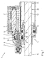
- FIG. 1 schematically illustrates a longitudinal section of an actuator 1 designed as a wheel actuator for a steer-by-wire steering system of a vehicle.
- a control and / or control device compares the desired value with an actual value of the steering angle and controls two electric motors 2, 2 '.
- the electric motors 2,2 ' are arranged in series and act on a shaft 11.
- the electric motors 2,2' provide u.a. an engine torque via a pinion 16 to a reduction gear 6 ready.
- the reduction gear 6 is formed to minimize in particular the width of the actuator 1 in two stages as a spur gear 14 with an intermediate 7.
- the idler 7 is rotatably connected to a rotary valve 8, which passes through a control bush 9.
- a torsion bar 17 which extends in the interior of the rotary valve 8 in the axial direction, the rotary valve 8 is rotationally connected to the control socket 9.
- the torsion bar 17 allows a relative rotation of the rotary valve 8 relative to the control bushing 9, whereby generated by the hydraulic control valve 3, a pressure difference of pressure medium in working spaces of the servo cylinder, not shown. An actuating movement of the servo cylinder is the result.
- the control bushing 9 has a wheel 10 at its periphery, whose longitudinal axis 18 is congruent with that of the intermediate gear 7, the control bush 9 and the rotary valve 8.
- the wheel meshes with a toothing 19 on the circumference of the trained as ball nut 12 component 4 of the movement screw 5.
- the axially immovably mounted, the rotational movement in a translational motion forming component 4 of the movement screw 5 cooperates with a trained as a spindle 20 push rod 13 and moves them axially in both directions.
- the push rod 13 forms a two-sided output 15 of the actuator. 1
- the ball screw of the ball nut 12 and the spindle 20 thus represents a third translation stage of the actuator 1.
- the actuator is due to the small radial distances of the shaft 11 of the electric motors 2,2 ', the longitudinal axis 18 and the spindle 20 to each other small, although a multi-stage Reduction gear and a high actuating force of the actuator are relativized.
- the servo cylinder instead of being arranged separately from the actuator 1, may also be formed together with the actuator 1 and preferably act on the push rod 13 or spindle 20. It is adaptable to the required size of the actuating force of the actuator 1.
Landscapes
- Engineering & Computer Science (AREA)
- Chemical & Material Sciences (AREA)
- Combustion & Propulsion (AREA)
- Transportation (AREA)
- Mechanical Engineering (AREA)
- Transmission Devices (AREA)
- Power Steering Mechanism (AREA)
Description
- Die Erfindung betrifft einen Aktuator, insbesondere einen Radaktuator für ein steer-by-wire-Lenksystem eines Fahrzeugs nach dem Oberbegriff des Anspruchs 1.
- Die DE 195 41 749 C1 beschreibt einen Aktuator für ein Lenksystem, bei dem die mechanische Zwangskoppelung zwischen einer Lenkhandhabe und gelenkten Rädern eines Fahrzeugs aufgehoben ist. Hierbei wird ein vorzugsweise als Elektromotor ausgebildeter Stellmotor von einer Regeleinrichtung angesteuert. Der Stellmotor dient zur Ansteuerung eines Stellventils eines Servozylinders zur Lenkverstellung gelenkter Räder und wirkt auch direkt auf ein als Zahnstangentrieb ausgebildetes Lenkgetriebe. Der Aktuator weist somit stets zwei Abtriebe auf und ist mit einem Lenkgetriebe verknüpft.
- Die DE 100 60 832 A 1 beschreibt einen Aktuator einer Fremdkraftlenkung nach dem steer-by-wire-Prinzip, mit einem Elektromotor zum Antrieb eines hydraulischen Stellventils für einen Servozylinder des Aktuators. Der Elektromotor ist so dimensioniert, dass er die Stellbewegung über ein Untersetzungsgetriebe, welches den Drehmomentenstrang über das hydraulische Stellventil zu einer Bewegungsschraube darstellt, bei Ausfall des Servozylinders alleine bewältigen kann.
- Der Aktuator wirkt über einen Abtrieb auf die gelenkten Räder. Sein Bauraum ist aufgrund des einstufigen Untersetzungsgetriebes nicht minimiert. Zudem eignet sich der Aktuator weniger für Lenksysteme von schweren Fahrzeugen.
- Der Erfindung liegt die Aufgabe zugrunde, einen Aktuator zu schaffen, der bei minimiertem Bauraumbedarf sich für Lenksysteme schwerer PKW und Nutzkraftwagen eignet.
- Die Aufgabe wird mit einem Aktuator mit den Merkmalen des Anspruchs 1 gelöst.
- Dadurch, dass ein Untersetzungsgetriebe den Drehmomentenstrang zwischen dem Elektromotor und dem Abtrieb des Aktuators bildet, welches zumindest zweistufig ist, ist eine schmale Bauform des Aktuators und eine hohe Übersetzung ins Langsame zur Darstellung großer Abtriebs-Stellkräfte geschaffen.
- Ein Zwischenrad des Untersetzungsgetriebes, welches bevorzugt von einem Rad oder Ritzel des Elektromotors getrieben ist, ist drehfest mit einem Drehschieber des hydraulischen Stellventils verbunden.
- Bevorzugte Ausführungen der Erfindung ergeben sich aus den Unteransprüchen.
- Der Drehschieber des hydraulischen Stellventils ist über ein Torsionselement, bevorzugt über einen Drehstab, mit einer Steuerbuchse des hydraulischen Stellventils rotatorisch wirkverbunden. Ein Rad an der Steuerbuchse treibt das axial unbewegliche, eine Drehbewegung in eine Translationsbewegung umformende Bauelement der Bewegungsschraube.
- Das Zwischenrad des Untersetzungsgetriebes ist somit in zwei, eine weitere Übersetzungsstufe bildende Räder an dem hydraulischen Stellventil, aufgeteilt. Bevorzugt ist die Übersetzung ins Langsame von dem Elektromotor zu dem Zwischenrad hoch gewählt, um die Drehzahl und die Anzahl der Umdrehungen des Drehschiebers und der Steuerbuchse zu minimieren.
- Es kann auch zweckmäßig sein, die Steuerbuchse des hydraulischen Stellventils von dem Ritzel des Elektromotors anzutreiben, wobei dann ein Rad an dem Drehschieber den weiteren Antrieb des axial unbeweglichen, eine Drehbewegung in eine Translationsbewegung umformenden Bauelementes der Bewegungsschraube übernimmt.
- Um eine hohe Stellkraft des Aktuators zu bewirken oder um den Aktuator teilredundant zu gestalten, ist es zweckmäßig zwei oder mehrere Elektromotoren vorzusehen, die bevorzugt auf eine Welle und ein Abtriebsrad oder Ritzel wirken. Das axial unbewegliche, eine Drehbewegung in deine Translationsbewegung umformende Bauelement der Bewegungsschraube ist bevorzugt als Mutter eines Kugelumlaufs ausgeführt, welche eine Schubstange oder Spindel des Aktuators in beide Richtungen verschiebt. Die Schubstange bildet bevorzugt einen zweiseitigen Abtrieb des Aktuators.
- Das Untersetzungsgetriebe kann als Stirnradgetriebe oder als Zugmittelgetriebe, wie etwa als Keilriemen-, Keilrippenriemen oder Zahnriemengetriebe ausgebildet sein.
- Der Servozylinder kann getrennt von dem Aktuator angeordnet sein, um insbesondere seine Größe an die erforderlichen Stellkräfte dem Zweck gemäß anzupassen. Der Servozylinder kann aber auch als Einheit mit dem Aktuator gebildet sein und bevorzugt auf die Schubstange oder Spindel des Aktuators wirken.
Das Untersetzungsgetriebe ist mit seiner Gesamtübersetzung von dem Rad der Elektromotoren bis zu der Bewegungsschraube so ausgelegt, dass bei Ausfall des Servozylinders die Elektromotoren eine Funktion des Aktuators und / oder des Lenksystems des Fahrzeugs aufrecht erhalten können. - Die Erfindung wird nun näher anhand eines Ausführungsbeispiels und anhand der beiliegenden Zeichnung beschrieben.
- Fig. 1
- zeigt einen schematischen Längsschnitt durch einen erfindungsgemäßen Aktuator.
- In der Fig. 1 ist ein als Radaktuator für ein steer-by-wire-Lenksystem eines Fahrzeugs ausgebildeter Aktuator 1 im Längsschnitt schematisch dargestellt.
- Durch die Betätigung einer nicht gezeigten Lenkhandhabe des Fahrzeugs wird ein Sollwert für den gewünschten Lenkwinkel der gelenkten Räder des Fahrzeugs generiert. Eine Regel- und / oder Steuereinrichtung vergleicht den Sollwert mit einem Ist-Wert des Lenkwinkels und steuert zwei Elektromotoren 2,2' an. Die Elektromotoren 2,2' sind in Reihe angeordnet und wirken auf eine Welle 11. Die Elektromotoren 2,2' stellen u.a. ein Motormoment über ein Ritzel 16 an ein Untersetzungsgetriebe 6 bereit.
- Das Untersetzungsgetriebe 6 ist zur Minimierung insbesondere der Breite des Aktuators 1 zweistufig als Stirnradgetriebe 14 mit einem Zwischenrad 7 gebildet. Das Zwischenrad 7 ist drehfest mit einem Drehschieber 8, der eine Steuerbuchse 9 durchragt, verbunden. Mit einem Drehstab 17, der im Inneren des Drehschiebers 8 in axialer Richtung verläuft, ist der Drehschieber 8 rotatorisch mit der Steuerbuchse 9 verbunden. Der Drehstab 17 ermöglicht eine Relativverdrehung des Drehschiebers 8 gegenüber der Steuerbuchse 9, wodurch durch das hydraulische Stellventil 3 eine Druckdifferenz von Druckmittel in Arbeitsräumen des nicht dargestellten Servozylinders erzeugt. Eine Stellbewegung des Servozylinders ist die Folge.
- Die Steuerbuchse 9 weist ein Rad 10 an ihrem Umfang auf, dessen Längsachse 18 mit der des Zwischenrads 7, der Steuerbuchse 9 und des Drehschiebers 8 kongruent ist. Das Rad kämmt mit einer Verzahnung 19 an dem Umfang des als Kugelumlaufmutter 12 ausgebildeten Bauelementes 4 der Bewegungsschraube 5. Das axial unbeweglich gelagerte, die Drehbewegung in eine Translationsbewegung umformende Bauelement 4 der Bewegungsschraube 5 wirkt mit einer als Spindel 20 ausgebildeten Schubstange 13 zusammen und verschiebt diese in beide Richtungen axial. Die Schubstange 13 bildet einen zweiseitigen Abtrieb 15 des Aktuators 1.
- Das Kugelgewinde der Kugelumlaufmutter 12 und der Spindel 20 stellt somit eine dritte Übersetzungsstufe des Aktuators 1 dar. Der Aktuator baut aufgrund der geringen radialen Abstände der Welle 11 der Elektromotoren 2,2', der Längsachse 18 und der Spindel 20 zueinander klein, obwohl ein mehrstufiges Untersetzungsgetriebe und eine hohe Stellkraft des Aktuators damit relativiert sind.
- Der Servozylinder kann anstatt getrennt von dem Aktuator 1 angeordnet zu sein auch zusammen mit dem Aktuator 1 gebildet sein und bevorzugt auf die Schubstange 13 oder Spindel 20 wirken. Er ist an die erforderliche Größe der Stellkraft des Aktuators 1 anpassbar.
BEZUGSZEICHENLISTE 1 Aktuator 26 2,2' Elektromotor 27 3 Stellventil, hydraulisch 28 4 Bauelement 29 5 Bewegungsschraube 30 6 Untersetzungsgetriebe 31 7 Zwischenrad 32 8 Drehschieber 33 9 Steuerbuchse 34 10 Rad 35 11 Welle 36 12 Kugelumlaufmutter 37 13 Schubstange 38 14 Stirnradgetriebe 39 15 Abtrieb, zweiseitig 40 16 Ritzel 41 17 Drehstab 42 18 Längsachse v. 10 43 19 Verzahnung 44 20 Spindel 45 21 46 22 47 23 48 24 49 25 50
Claims (11)
- Aktuator, insbesondere Radaktuator für ein steer-by-wire-Lenksystem eines Fahrzeugs, mit einem Elektromotor (2) zum Antrieb eines hydraulischen Stellventils (3) für einen Servozylinder des Aktuators (1) und zum Antrieb eines axial unbeweglichen, eine Drehbewegung in eine Translationsbewegung umformenden Bauelementes (4) einer Bewegungsschraube (5) des Aktuators (1), wobei ein Untersetzungsgetriebe (6) und ein Torsionselement (17) in dem Drehmomentenstrang zwischen dem Elektromotor (2), dem hydraulischen Stellventil (3) und der Bewegungsschraube (5) angeordnet ist, dadurch gekennzeichnet, dass das Untersetzungsgetriebe (6) zumindest zweistufig gebildet ist, wobei der Elektromotor (2) ein Zwischenrad (7) antreibt, das drehfest mit einem Drehschieber (8) des hydraulischen Stellventils (3) verbunden ist, und eine Steuerbuchse (9) des hydraulischen Stellventils (3) mit einem Rad (10) das Bauelement (4) der Bewegungsschraube (5) antreibt.
- Aktuator, insbesondere Radaktuator für ein steer-by-wire-Lenksystem eines Fahrzeugs, mit einem Elektromotor (2) zum Antrieb eines hydraulischen Stellventils (3) für einen Servozylinder des Aktuators (1) und zum Antrieb eines axial unbeweglichen, eine Drehbewegung in eine Translationsbewegung umformenden Bauelementes (4) einer Bewegungsschraube (5) des Aktuators (1), wobei ein Untersetzungsgetriebe (6) und ein Torsionselement (17) in dem Drehmomentenstrang zwischen dem Elektromotor (2), dem hydraulischen Stellventil (3) und der Bewegungsschraube (5) angeordnet ist, dadurch gekennzeichnet, dass das Untersetzungsgetriebe (6) zumindest zweistufig gebildet ist, wobei der Elektromotor (2) ein Zwischenrad (7) antreibt, das drehfest mit einer Steuerbuchse (9) des hydraulischen Stellventils (3) verbunden ist, und ein Drehschieber (8) des hydraulischen Stellventils (3) mit einem Rad (10) das Bauelement (4) der Bewegungsschraube (5) antreibt.
- Aktuator nach einem der Ansprüche 1 oder 2, dadurch gekennzeichnet, dass zwei oder mehrere Elektromotoren (2,2') vorgesehen sind, die auf eine gemeinsame Welle (11) wirken.
- Aktuator nach einem der Ansprüche 1 bis 3, dadurch gekennzeichnet, dass das axial unbewegliche, eine Drehbewegung in eine Translationsbewegung umformende Bauelement (4) der Bewegungsschraube (5) eine Kugelumlaufmutter (12) ist, welche eine Schubstange (13) oder Spindel (20) des Aktuators (1) verschiebt.
- Akutator nach einem der Ansprüche 1 bis 4, dadurch gekennzeichnet, dass das Untersetzungsgetriebe (6) als Stirnradgetriebe (14), als Keilriemen-, Keilrippenriemen-, oder Zahnriemengetriebe ausgebildet ist.
- Aktuator nach einem der Ansprüche 1 bis 5, dadurch gekennzeichnet, dass der Servozylinder getrennt zu der Bewegungsschraube (5) des Aktuators (1) angeordnet ist.
- Aktuator nach einem der Ansprüche 1 bis 6, dadurch gekennzeichnet, dass das Untersetzungsgetriebe (6) so übersetzt ist, dass bei Ausfall des Servozylinders der Elektromotor (2,2') eine Funktion des Aktuators (1) und / oder des Lenksystems des Fahrzeugs aufrecht erhalten kann.
- Aktuator nach einem der Ansprüche 1 bis 7, dadurch gekennzeichnet, dass der Servozylinder an die Größe des Fahrzeugs angepasst ist.
- Aktuator nach einem der Ansprüche 4 bis 8, dadurch gekennzeichnet, dass die Schubstange (13) einen zweiseitigen Abtrieb (15) des Aktuators (1) bildet.
- Lenksystem mit Aktuator nach Anspruch 1, dadurch gekennzeichnet, dass das Untersetzungsgetriebe (6) zumindest zweistufig gebildet ist, wobei der Elektromotor (2) ein Zwischenrad (7) antreibt, das drehfest mit einem Drehschieber (8) des hydraulischen Stellventils (3) verbunden ist, und eine Steuerbuchse (9) des hydraulischen Stellventils (3) mit einem Rad (10) das Bauelement (4) der Bewegungsschraube (5) antreibt.
- Lenksystem mit Aktuator nach Anspruch 2, dadurch gekennzeichnet, dass das Untersetzungsgetriebe (6) zumindest zweistufig gebildet ist, wobei der Elektromotor (2) ein Zwischenrad (7) antreibt, das drehfest mit einer Steuerbuchse (9) des hydraulischen Stellventils (3) verbunden ist, und ein Drehschieber (8) des hydraulischen Stellventils (3) mit einem Rad (10) das Bauelement (4) der Bewegungsschraube (5) antreibt.
Applications Claiming Priority (2)
| Application Number | Priority Date | Filing Date | Title |
|---|---|---|---|
| DE2003131598 DE10331598A1 (de) | 2003-07-11 | 2003-07-11 | Aktuator |
| DE10331598 | 2003-07-11 |
Publications (2)
| Publication Number | Publication Date |
|---|---|
| EP1495943A1 EP1495943A1 (de) | 2005-01-12 |
| EP1495943B1 true EP1495943B1 (de) | 2006-09-06 |
Family
ID=33441743
Family Applications (1)
| Application Number | Title | Priority Date | Filing Date |
|---|---|---|---|
| EP20040016050 Expired - Lifetime EP1495943B1 (de) | 2003-07-11 | 2004-07-08 | Aktuator für Lenkgetriebe |
Country Status (2)
| Country | Link |
|---|---|
| EP (1) | EP1495943B1 (de) |
| DE (2) | DE10331598A1 (de) |
Families Citing this family (3)
| Publication number | Priority date | Publication date | Assignee | Title |
|---|---|---|---|---|
| DE102005019287A1 (de) * | 2005-04-26 | 2006-11-09 | Schaeffler Kg | Elektromechanische Servolenkung |
| DE102006012598B4 (de) * | 2006-03-18 | 2010-10-07 | Zf Lenksysteme Gmbh | Wälzlager |
| DE102010028153A1 (de) | 2010-04-23 | 2011-10-27 | Zf Lenksysteme Gmbh | Servolenkung |
Family Cites Families (5)
| Publication number | Priority date | Publication date | Assignee | Title |
|---|---|---|---|---|
| GB1424937A (en) * | 1973-03-05 | 1976-02-11 | Nissan Motor | Automotive steering system process for the production of bis-halogen carbonyl anilines |
| US4655092A (en) * | 1985-05-02 | 1987-04-07 | Taig Alistair G | Transducer coupling |
| EP0309460B1 (de) * | 1986-05-14 | 1990-02-07 | ZF FRIEDRICHSHAFEN Aktiengesellschaft | Hilfskraftlenkung für kraftfahrzeuge |
| DE19541749C1 (de) * | 1995-11-09 | 1997-05-22 | Daimler Benz Ag | Servolenkung für Kraftfahrzeuge |
| DE10060832A1 (de) * | 2000-12-07 | 2002-06-13 | Zf Lenksysteme Gmbh | Fremdkraft-Lenkeinrichtung |
-
2003
- 2003-07-11 DE DE2003131598 patent/DE10331598A1/de not_active Withdrawn
-
2004
- 2004-07-08 EP EP20040016050 patent/EP1495943B1/de not_active Expired - Lifetime
- 2004-07-08 DE DE200450001388 patent/DE502004001388D1/de not_active Expired - Fee Related
Also Published As
| Publication number | Publication date |
|---|---|
| EP1495943A1 (de) | 2005-01-12 |
| DE10331598A1 (de) | 2005-02-10 |
| DE502004001388D1 (de) | 2006-10-19 |
Similar Documents
| Publication | Publication Date | Title |
|---|---|---|
| EP1237777B1 (de) | Lenkvorrichtung für kraftfahrzeuge | |
| WO2005054035A1 (de) | Überlagerungslenkung für ein fahrzeug | |
| EP3464947B1 (de) | Stelleinrichtung und verwendung der stelleinrichtung | |
| DE3708059A1 (de) | Motorgetriebene servolenkungseinrichtung | |
| DE4243267B4 (de) | Lenkgetriebe | |
| EP0827472B1 (de) | Hilfskraftlenkung für kraftfahrzeuge | |
| EP1713679B1 (de) | Lenksystem für ein fahrzeug | |
| DE10160313A1 (de) | Überlagerungsgetriebe für eine Überlagerungslenkung | |
| EP1495943B1 (de) | Aktuator für Lenkgetriebe | |
| EP1716037B1 (de) | Hydraulische servolenkung | |
| WO2005007487A1 (de) | Aktuator, insbesondere radaktuator mit einem abtrieb | |
| EP3833891B1 (de) | Zweistufiges zahnstangengetriebe | |
| EP2585357A1 (de) | Rotatorisch abgestützte lenkspindel | |
| DE2104037C3 (de) | Servolenksystem | |
| DE10234596B3 (de) | Als Kugelumlauflenkung ausgebildete elektrische Servolenkung eines Kraftfahrzeuges | |
| DE102016212818A1 (de) | Lenkung für Fahrzeuge mit Hochübersetzungsgetriebe, insbesondere für Nutzkraftfahrzeuge | |
| DE102007057391A1 (de) | Zahnstangen-Hilfskraftlenkung | |
| DE102005014560B4 (de) | Überlagerungslenkung für ein Fahrzeug | |
| EP1717128B1 (de) | Zahnstangenlenkung mit Antrieb über einen Kugelumlauf | |
| DE102007010003A1 (de) | Lenkgetriebe | |
| DE102007005713A1 (de) | Lenkgetriebe | |
| EP1431161A2 (de) | Lenksystem für ein Fahrzeug | |
| DE19931850A1 (de) | Kraftfahrzeugservolenkung mit elektrischem Servomotor und Planetenwälzgetriebespindeltrieb | |
| DE102007001823A1 (de) | Überlagerungslenkung | |
| DE69019276T2 (de) | Servolenkeinrichtung. |
Legal Events
| Date | Code | Title | Description |
|---|---|---|---|
| PUAI | Public reference made under article 153(3) epc to a published international application that has entered the european phase |
Free format text: ORIGINAL CODE: 0009012 |
|
| AK | Designated contracting states |
Kind code of ref document: A1 Designated state(s): AT BE BG CH CY CZ DE DK EE ES FI FR GB GR HU IE IT LI LU MC NL PL PT RO SE SI SK TR |
|
| AX | Request for extension of the european patent |
Extension state: AL HR LT LV MK |
|
| 17P | Request for examination filed |
Effective date: 20050122 |
|
| 17Q | First examination report despatched |
Effective date: 20050502 |
|
| AKX | Designation fees paid |
Designated state(s): DE ES FR GB IT SE |
|
| GRAP | Despatch of communication of intention to grant a patent |
Free format text: ORIGINAL CODE: EPIDOSNIGR1 |
|
| GRAS | Grant fee paid |
Free format text: ORIGINAL CODE: EPIDOSNIGR3 |
|
| GRAA | (expected) grant |
Free format text: ORIGINAL CODE: 0009210 |
|
| AK | Designated contracting states |
Kind code of ref document: B1 Designated state(s): DE ES FR GB IT SE |
|
| PG25 | Lapsed in a contracting state [announced via postgrant information from national office to epo] |
Ref country code: IT Free format text: LAPSE BECAUSE OF FAILURE TO SUBMIT A TRANSLATION OF THE DESCRIPTION OR TO PAY THE FEE WITHIN THE PRESCRIBED TIME-LIMIT;WARNING: LAPSES OF ITALIAN PATENTS WITH EFFECTIVE DATE BEFORE 2007 MAY HAVE OCCURRED AT ANY TIME BEFORE 2007. THE CORRECT EFFECTIVE DATE MAY BE DIFFERENT FROM THE ONE RECORDED. Effective date: 20060906 Ref country code: GB Free format text: LAPSE BECAUSE OF FAILURE TO SUBMIT A TRANSLATION OF THE DESCRIPTION OR TO PAY THE FEE WITHIN THE PRESCRIBED TIME-LIMIT Effective date: 20060906 |
|
| REG | Reference to a national code |
Ref country code: GB Ref legal event code: FG4D Free format text: NOT ENGLISH |
|
| REF | Corresponds to: |
Ref document number: 502004001388 Country of ref document: DE Date of ref document: 20061019 Kind code of ref document: P |
|
| PG25 | Lapsed in a contracting state [announced via postgrant information from national office to epo] |
Ref country code: ES Free format text: LAPSE BECAUSE OF FAILURE TO SUBMIT A TRANSLATION OF THE DESCRIPTION OR TO PAY THE FEE WITHIN THE PRESCRIBED TIME-LIMIT Effective date: 20061217 |
|
| REG | Reference to a national code |
Ref country code: SE Ref legal event code: TRGR |
|
| GBV | Gb: ep patent (uk) treated as always having been void in accordance with gb section 77(7)/1977 [no translation filed] |
Effective date: 20060906 |
|
| ET | Fr: translation filed | ||
| PLBE | No opposition filed within time limit |
Free format text: ORIGINAL CODE: 0009261 |
|
| STAA | Information on the status of an ep patent application or granted ep patent |
Free format text: STATUS: NO OPPOSITION FILED WITHIN TIME LIMIT |
|
| 26N | No opposition filed |
Effective date: 20070607 |
|
| PGFP | Annual fee paid to national office [announced via postgrant information from national office to epo] |
Ref country code: DE Payment date: 20080717 Year of fee payment: 5 |
|
| PGFP | Annual fee paid to national office [announced via postgrant information from national office to epo] |
Ref country code: FR Payment date: 20080718 Year of fee payment: 5 Ref country code: IT Payment date: 20080729 Year of fee payment: 5 |
|
| PGRI | Patent reinstated in contracting state [announced from national office to epo] |
Ref country code: IT Effective date: 20081001 |
|
| PGFP | Annual fee paid to national office [announced via postgrant information from national office to epo] |
Ref country code: SE Payment date: 20080709 Year of fee payment: 5 |
|
| EUG | Se: european patent has lapsed | ||
| REG | Reference to a national code |
Ref country code: FR Ref legal event code: ST Effective date: 20100331 |
|
| PG25 | Lapsed in a contracting state [announced via postgrant information from national office to epo] |
Ref country code: FR Free format text: LAPSE BECAUSE OF NON-PAYMENT OF DUE FEES Effective date: 20090731 |
|
| PG25 | Lapsed in a contracting state [announced via postgrant information from national office to epo] |
Ref country code: DE Free format text: LAPSE BECAUSE OF NON-PAYMENT OF DUE FEES Effective date: 20100202 |
|
| PG25 | Lapsed in a contracting state [announced via postgrant information from national office to epo] |
Ref country code: IT Free format text: LAPSE BECAUSE OF NON-PAYMENT OF DUE FEES Effective date: 20090708 |
|
| PG25 | Lapsed in a contracting state [announced via postgrant information from national office to epo] |
Ref country code: SE Free format text: LAPSE BECAUSE OF NON-PAYMENT OF DUE FEES Effective date: 20090709 |