EP3833891B1 - Zweistufiges zahnstangengetriebe - Google Patents
Zweistufiges zahnstangengetriebe Download PDFInfo
- Publication number
- EP3833891B1 EP3833891B1 EP19755556.8A EP19755556A EP3833891B1 EP 3833891 B1 EP3833891 B1 EP 3833891B1 EP 19755556 A EP19755556 A EP 19755556A EP 3833891 B1 EP3833891 B1 EP 3833891B1
- Authority
- EP
- European Patent Office
- Prior art keywords
- gear
- rack
- stage
- driving
- pinion
- Prior art date
- Legal status (The legal status is an assumption and is not a legal conclusion. Google has not performed a legal analysis and makes no representation as to the accuracy of the status listed.)
- Active
Links
Images


Classifications
-
- F—MECHANICAL ENGINEERING; LIGHTING; HEATING; WEAPONS; BLASTING
- F16—ENGINEERING ELEMENTS AND UNITS; GENERAL MEASURES FOR PRODUCING AND MAINTAINING EFFECTIVE FUNCTIONING OF MACHINES OR INSTALLATIONS; THERMAL INSULATION IN GENERAL
- F16H—GEARING
- F16H19/00—Gearings comprising essentially only toothed gears or friction members and not capable of conveying indefinitely-continuing rotary motion
- F16H19/02—Gearings comprising essentially only toothed gears or friction members and not capable of conveying indefinitely-continuing rotary motion for interconverting rotary or oscillating motion and reciprocating motion
- F16H19/04—Gearings comprising essentially only toothed gears or friction members and not capable of conveying indefinitely-continuing rotary motion for interconverting rotary or oscillating motion and reciprocating motion comprising a rack
-
- F—MECHANICAL ENGINEERING; LIGHTING; HEATING; WEAPONS; BLASTING
- F16—ENGINEERING ELEMENTS AND UNITS; GENERAL MEASURES FOR PRODUCING AND MAINTAINING EFFECTIVE FUNCTIONING OF MACHINES OR INSTALLATIONS; THERMAL INSULATION IN GENERAL
- F16H—GEARING
- F16H1/00—Toothed gearings for conveying rotary motion
- F16H1/02—Toothed gearings for conveying rotary motion without gears having orbital motion
- F16H1/20—Toothed gearings for conveying rotary motion without gears having orbital motion involving more than two intermeshing members
- F16H1/203—Toothed gearings for conveying rotary motion without gears having orbital motion involving more than two intermeshing members with non-parallel axes
-
- F—MECHANICAL ENGINEERING; LIGHTING; HEATING; WEAPONS; BLASTING
- F16—ENGINEERING ELEMENTS AND UNITS; GENERAL MEASURES FOR PRODUCING AND MAINTAINING EFFECTIVE FUNCTIONING OF MACHINES OR INSTALLATIONS; THERMAL INSULATION IN GENERAL
- F16H—GEARING
- F16H55/00—Elements with teeth or friction surfaces for conveying motion; Worms, pulleys or sheaves for gearing mechanisms
- F16H55/02—Toothed members; Worms
- F16H55/08—Profiling
- F16H55/0806—Involute profile
Definitions
- the invention relates to a two-stage rack and pinion gear which converts a rotational movement of a drive shaft at the gear input into a linear movement of a toothed rack at the gear output.
- Rack and pinion gears coupled to a drive on the input side are used for positioning and movement tasks, for example in robotics, assembly and automation technology, conveyor technology, process engineering and testing technology.
- the geometry of a rack with straight or helical teeth corresponds to the developed geometry of a spur gear.
- a rack meshing with an externally toothed spur gear represents a special case of spur gear teeth.
- a special application of rack and pinion gears are window drives.
- motorized window drives are used to automatically open ventilation windows, cupolas, top-hung windows and skylights for natural building ventilation; they take over the actuation of the windows and the movement of the window sash.
- These motor drives are also used for smoke and heat extraction systems.
- rack and pinion drives are very resistant to pressure and buckling, However, they have a high dead weight and can represent a visual impairment due to their dimensions.
- the rack and pinion gears for window drives known from the prior art have five to eight gear stages in order to reduce the motor speed.
- the individual gear stages are spur gear stages.
- multi-stage gears have the advantage of dividing the desired transmission ratio between several smaller gears and thus keeping the overall dimensions of the gear small. Nevertheless, the large number of gear stages required leads to dimensions of the window drive that can impair the visual appearance.
- a rack and pinion drive for an actuating cylinder of a drum brake is known, with an electric motor being provided for driving the rack toothed on both sides, the motor shaft of which is provided at the end with a few-toothed pinion, for example with a 2-toothed pinion.
- the rotation of the motor shaft is transmitted to the rack by two pairs of spur gears.
- Each pair of spur gears consists of a first spur gear and a second spur gear.
- the few-tooth pinion engages in both first spur gears, while the two second spur gears each engage in a toothing of the toothed rack, which is toothed on both sides.
- the U.S. 6,139,070 discloses a multi-stage rack and pinion gear for a window lock, wherein the first gear stage is a worm gear stage and the The second, third and fourth gear stages are spur gear stages, the fourth gear stage having a straight-toothed gear wheel as the driving gear element and a straight-toothed rack as the driven gear element.
- the invention is based on the object of proposing a multi-stage rack and pinion gear, particularly for use in window drives, which can transmit large thrust forces with a high gear ratio with particularly compact dimensions compared to the prior art.
- a rack and pinion gear having the features of claim 1.
- the pairing between a driving gear element and a driven gear element, at which the speed and/or the torque change, is referred to as a gear stage.
- Each gear stage which includes wheels as the driving and driven gear element, is assigned a specific transmission ratio to reduce it, i.e. the speed of the driven wheel is lower than the speed of the driving wheel.
- causes the torques in the upstream gear stage at higher speeds at the same time are less.
- the upstream gear stage can therefore be dimensioned weaker and consequently made more compact.
- the motor which is connected to the first gear stage and works on the drive shaft, can be made more compact.
- the overall transmission ratio i tot of the multi-stage rack and pinion gear is preferably i tot ⁇ 60:1.
- the first gear stage is a worm gear stage, which has a worm as the driving member and a worm wheel as the driven member.
- the worm is a special form of a helical gear wheel.
- the angle of the helical gearing is so large that a tooth turns helically around several times the wheel axle twists.
- the tooth in this case is called a gear.
- the worm gear qualifies as a gear stage that has wheels as the driving and driven gear members.
- the self-locking prevents reverse rotation of the motor connected to the gear input, in particular the electric motor, due to the load acting on the gear output, which is of particular importance for window drives after the desired opening angle has been set.
- worm gear stage as the first gear stage allows the axis of rotation of the input-side drive shaft to be positioned at right angles to the axis of rotation of the drive wheel of the subsequent gear stage.
- the driving element of the worm gear stage is arranged on the drive shaft at the gear input.
- the drive shaft can be connected to the drive via an elastic coupling.
- the geometry of a toothed rack (2) corresponds to the developed geometry of a gear wheel with external teeth. The distance from one tooth to the next tooth is the pitch of the rack. The division divided by n gives the module of the rack.
- the rack can have spur gearing (2.2) or helical gearing (2.1).
- figure 2 shows a first embodiment of a two-stage rack and pinion gear according to the invention, which converts a rotational movement of a drive shaft (3) at the gear input into a linear movement (4) of the rack (2) converted at the transmission output.
- the worm wheel (5) meshes with a worm (6) which is non-rotatably connected to the drive shaft (3) at the gearbox input.
- the drive shaft (3) is the motor shaft of a drive (7), which is designed as an electric motor.
- the first gear stage is a worm gear stage, which has the worm (6) as the driving element and the worm wheel (5) as the driven element.
- This gearbox design is particularly compact and allows the drive shaft of the electric motor to be arranged parallel to the longitudinal axis (2.3) of the toothed rack (2).
- Figures 3 , 4 also show a two-stage rack and pinion gear.
- the rack and pinion gear adjusts in the structure Figures 3 , 4 largely with the rack and pinion gear figure 2 match.
- the drive shaft (3) can be coupled to the drive (7) via an elastic coupling.
- the elastic coupling is designed as a torsionally flexible coupling, for example a hose coupling made of an elastic material, for example rubber.
- the elastic coupling can both compensate for a small axis offset between the drive shaft (3) and the motor shaft of the drive (7) and dampen effective torque peaks between the first gear stage and the drive (7).
- the particular advantage of the invention consists in the high transmission ratios that can be achieved, the high forces that can be transmitted with the toothed rack, the number of gear stages reduced to two and the associated particularly small volume of installation space.
- No. designation 1. gear 1.1 axis of rotation 2. rack 2.1 helical gearing 2.2 gear teeth 2.3 longitudinal axis 4. linear motion 5. worm wheel 6. Snail 7. drive
Landscapes
- Engineering & Computer Science (AREA)
- General Engineering & Computer Science (AREA)
- Mechanical Engineering (AREA)
- Transmission Devices (AREA)
Description
- Die Erfindung betrifft ein zweistufiges Zahnstangengetriebe, welches eine Rotationsbewegung einer Antriebswelle am Getriebeeingang in eine Linearbewegung einer Zahnstange am Getriebeausgang umwandelt.
- Getriebe, welche mithilfe einer Zahnstange eine Rotationsbewegung in eine Linearbewegung umwandeln, werden als Zahnstangengetriebe bezeichnet. Eingangsseitig an einen Antrieb gekoppelte Zahnstangengetriebe werden für Positionier- und Bewegungsaufgaben beispielsweise in der Robotik, der Montage- und Automatisierungstechnik, der Fördertechnik, der Verfahrenstechnik und Prüftechnik verwendet. Die Geometrie einer Zahnstange in geradverzahnter oder schrägverzahnter Ausführung entspricht der abgewickelten Geometrie eines Stirnrades. Insofern stellt eine mit einem außenverzahnten Stirnrad im Eingriff stehende Zahnstange ein Sonderfall einer Stirnradverzahnung dar.
- Ein besonderer Anwendungsfall der Zahnstangengetriebe stellen Fensterantriebe dar. In vielen Fällen ist es nicht oder nur schwer möglich, Fenster von Hand zu betätigen, zu Öffnen und zu Kippen. Neben der Steigerung des Bedienkomforts werden motorische Fensterantriebe zur automatischen Öffnung von Lüftungsfenstern, Kuppeln, Klappfenstern und Oberlichtern für die natürliche Gebäudelüftung eingesetzt; sie übernehmen die Betätigung der Fenster und das Bewegen des Fensterflügels. Diese motorischen Antriebe kommen auch für Rauch-Wärme-Abzugsanlagen zum Einsatz. Zahnstangenantriebe sind im Gegensatz zu Kettenmotoren sehr druck- und knickstabil, weisen jedoch ein hohes Eigengewicht auf und können aufgrund ihrer Abmessungen eine optische Beeinträchtigung darstellen.
- Um die erforderlichen hohen Schubkräfte von teilweise mehr als 1200 N aufzubringen, weisen die aus dem Stand der Technik bekannten Zahnstangengetriebe für Fensterantriebe fünf bis acht Getriebestufen auf, um die Motordrehzahl zu untersetzen. Bei den einzelnen Getriebestufen handelt es sich um Stirnradgetriebestufen. Grundsätzlich haben mehrstufige Getriebe den Vorteil, das gewünschte Übersetzungsverhältnis auf mehrere kleinere Zahnräder aufzuteilen und so die Abmessungen des Getriebes insgesamt klein zu halten. Gleichwohl führt die große Anzahl der erforderlichen Getriebestufen zu Abmessungen des Fensterantriebs, die das optische Bild beeinträchtigen können.
- Aus der
DE 10 2014 226 265 A1 ist ein Zahnstangenantrieb für einen Betätigungszylinder einer Trommelbremse bekannt, wobei zum Antrieb der beidseitig verzahnten Zahnstange ein Elektromotor vorgesehen ist, dessen Motorwelle endseitig mit einem Wenigzahnritzel, beispielsweise mit einem 2-Zahnritzel, versehen ist. Die Drehbewegung der Motorwelle wird durch zwei Paare von Stirnzahnrädern auf die Zahnstange übertragen. Jedes Stirnradpaar besteht aus einem ersten Stirnzahnrad und einem zweiten Stirnzahnrad. Das Wenigzahnritzel greift in beide ersten Stirnzahnräder ein, während die beiden zweiten Stirnzahnräder jeweils in eine Verzahnung der beidseitig verzahnten Zahnstange eingreifen. - Die
US 6,139 070 offenbart ein mehrstufiges Zahnstangengetriebe für eine Fensterverriegelung, wobei die erste Getriebestufe eine Schneckengetriebestufe und die zweite, dritte und vierte Getriebestufe Stirnradgetriebestufen sind, wobei die vierte Getriebestufe als treibendes Getriebeglied ein geradverzahntes Zahnrad und als getriebenes Getriebeglied eine geradverzahnte Zahnstange aufweist. - Roth, K: "Stirnradpaarungen mit 1 - bis 5 zähnigen Ritzeln im Maschinenbau", Springer, Berlin, Konstruktion 26 (1974), S. 425 -429, offenbart, dass das Gesamtübersetzungsverhältnis, welches sich aus dem Stufenübersetzungsverhältnis und der Anzahl der Stufen ergibt, die Änderung der Drehzahl bzw. des Drehmoments bestimmt. Bei einem großen Stufenübersetzungsverhältnis kann die Stufenzahl und damit auch die Anzahl der Lagerstellen verringert werden; bei gleichen Abmessungen des größeren Rades wird dann das gesamte Getriebe kleiner. Evolventenverzahnungen bis zur Zähnezahl z=1 werden erwähnt, die mit normverzahnten Gegenrädern kämmen.
- Ausgehend von diesem Stand der Technik liegt der Erfindung die Aufgabe zugrunde, ein mehrstufiges Zahnstangengetriebe, insbesondere für die Verwendung in Fensterantrieben, vorzuschlagen, welches mit einer hohen Übersetzung große Schubkräfte bei im Vergleich zum Stand der Technik besonders kompakten Abmessungen übertragen kann.
- Die Lösung basiert auf einem Zahnstangengetriebe mit zwei Getriebestufen, wobei eine der beiden Getriebestufen eine Stirnradgetriebestufe ist, die als treibendes Getriebeglied ein Zahnrad mit der Zähnezahl Z = 1 aufweist, welches unmittelbar in die Verzahnung der Zahnstange am Getriebeausgang eingreift. Im Einzelnen wird die Aufgabe durch ein Zahnstangengetriebe mit den Merkmalen des Anspruchs 1 gelöst.
- Als Getriebestufe wird die Paarung zwischen einem treibenden Getriebeglied und einem getriebenen Getriebeglied bezeichnet, an der sich die Drehzahl und/oder das Drehmoment ändern.
- Jeder Getriebestufe, die Räder als treibendes und getriebenes Getriebeglied umfasst, ist ein bestimmtes Übersetzungsverhältnis in das Langsame zugeordnet, d.h. die Drehzahl des getriebenen Rades ist geringer als die Drehzahl des treibenden Rades.
- Soweit zwei Räder drehfest auf einer gemeinsamen Welle sitzen, ist deren Drehzahl identisch und es findet weder eine Änderung der Drehzahl noch eine Änderung des Drehmomentes statt. Bei diesen Rädern handelt es sich daher nicht um eine Getriebestufe.
- Bei übereinstimmendem Gesamt-Übersetzungsverhältnis und übereinstimmender Schubkraft eines mehrstufigen Zahnstangengetriebes nach dem Stand der Technik und eines erfindungsgemäßen Zahnstangengetriebes bewirkt die erfindungsgemäß vorgesehene zweite Getriebestufe umfassend die Zahnstange und das Zahnrad mit der Zähnezahl Z=1, dass die Momente in der vorgeschalteten Getriebestufe bei zugleich höheren Drehzahlen geringer sind. Die vorgeschaltete Getriebestufe kann daher schwächer dimensioniert und infolgedessen kompakter ausgeführt werden. Zudem kann aufgrund des höheren Drehzahlniveaus der mit der ersten Getriebestufe verbundenem, auf die Antriebswelle arbeitendem Motor kompakter ausgeführt werden. Das Modul der zweiten Getriebestufe lässt sich problemlos derart dimensionieren, dass die hohen Momente von dem Zahnrad mit Z=1 auf die Zahnstange übertragen werden können.
- Bei einer Zähnezahl Z = 1 lassen sich in der zweiten Getriebestufe besonders hohe Übersetzungsverhältnisse realisieren. Das hohe Übersetzungsverhältnis in der zweiten Getriebestufe erlaubt eine Reduktion der Anzahl der Getriebestufen auf zwei Getriebestufen mit weiteren Vorteilen für den Bauraum.
- Weist die Zahnstange eine Geradverzahnung auf, verläuft die Rotationsachse des Zahnrades mit der maximalen Zähnezahl Z = 1 unter einem spitzen Winkel zur Längsachse der Zahnstange. Weist die Zahnstange eine Schrägverzahnung auf, verläuft die Rotationsachse des Zahnrades mit der maximalen Zähnezahl Z = 1 unter einem rechten Winkel zur Längsachse der Zahnstange. Abhängig von den Raumverhältnissen kann daher durch Wahl der Verzahnung die Lage des Zahnrades mit der Zähnezahl Z = 1 in der letzten Getriebestufe in Richtung des Getriebeausgangs angepasst werden.
- Das Gesamt-Übersetzungsverhältnis iges des mehrstufigen Zahnstangengetriebes ist vorzugsweise iges ≥ 60:1 ist.
- Aufgrund der hohen realisierbaren Übersetzungen und der Selbsthemmung ist die erste Getriebestufen eine Schneckengetriebestufe, die als treibendes Glied eine Schnecke und als getriebenes Glied ein Schneckenrad aufweist. Die Schnecke ist eine Sonderform eines schrägverzahnten Zahnrades. Der Winkel der Schrägverzahnung ist so groß, dass ein Zahn sich mehrfach schraubenförmig um die Radachse windet. Der Zahn wird in diesem Fall als Gang bezeichnet. Infolgedessen qualifiziert sich das Schneckengetriebe als Getriebestufe, die Räder als treibende und getriebene Getriebeglieder aufweist. Die Selbsthemmung unterbindet eine Rückdrehung des mit dem Getriebeeingang verbundenen Motors, insbesondere Elektromotors, aufgrund der am Getriebeausgang wirkenden Last, was insbesondere für Fensterantriebe nach Einstellung des gewünschten Öffnungswinkels von besonderer Bedeutung ist. Die Selbsthemmung tritt durch Gleitreibung zwischen Schnecke und Schneckenrad bei hoher Übersetzung und geringen Gangzahlen sowie einem Steigungswinkel der Schnecke γ kleiner 5° ein. Darüber hinaus trägt die Schnecke aufgrund ihrer Schrägverzahnung zur Geräuschminderung des mehrstufigen Zahnstangengetriebes bei. Ferner erlaubt eine Schneckengetriebestufe als erste Getriebestufe eine rechtwinklige Lage der Rotationsachse der eingangsseitigen Antriebswelle zu der Rotationsachse des Antriebsrades der nachfolgenden Getriebestufe.
- Erfindungsgemäß ist das treibende Glied der Schneckengetriebestufe auf der Antriebswelle am Getriebeeingang angeordnet. Um eine Stoßdämpfung für den eingangsseitig mit der Antriebswelle zu koppelnden Antrieb zu bewirken, ist in einer vorteilhaften Ausgestaltung der Erfindung die Antriebswelle über eine elastische Kupplung mit dem Antrieb verbindbar.
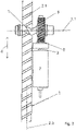
- Nachfolgend wird die Erfindung anhand der Zeichnungen näher erläutert. Es zeigen
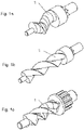
- Figuren 1 a - c
- perspektivische Darstellungen außenverzahnter Zahnräder mit einer Zähnezahl Z=1, Z=2 und Z=3,
- Figur 2
- eine Aufsicht auf eine erste Ausführungsform eines zweistufigen Zahnstangengetriebes,
- Figur 3
- eine Aufsicht auf eine zweite Ausführungsform eines zweistufigen Zahnstangengetriebes und
- Figur 4
- eine perspektivische Ansicht des Zahnstangengetriebes nach
Figur 3 . -
Figur 1a zeigt ein Zahnrad (1) mit der Zähnezahl Z=1.Figur 1b zeigt ein Zahnrad (1) mit der Zähnezahl Z=2.Figur 1c zeigt ein Zahnrad mit der Zähnezahl Z=3. - Die Geometrie einer Zahnstange (2) entspricht der abgewickelten Geometrie eines Zahnrades mit Außenverzahnung. Der Abstand von einem Zahn zum nächsten Zahn ist die Teilung der Zahnstange. Die Teilung dividiert durch n ergibt das Modul der Zahnstange. Die Zahnstange kann eine Gradverzahnung (2.2) oder Schrägverzahnung (2.1) aufweisen.
- Das Zahnrad (1) mit der Zähnezahl Z=1 steht mit der Zahnstange (2) in Eingriff. Die zweite Getriebestufe wird nachfolgend auch als "Stirnradgetriebestufe Z=1 " bezeichnet.
-
Figur 2 zeigt ein erstes Ausführungsbeispiel eines erfindungsgemäßen zweistufigen Zahnstangengetriebes, welches eine Rotationsbewegung einer Antriebswelle (3) am Getriebeeingang in eine Linearbewegung (4) der Zahnstange (2) am Getriebeausgang umwandelt. Die Zahnstange (2) weist im dargestellten Ausführungsbeispiel eine Schrägverzahnung (2.1) auf, die mit einem Zahnrad (1) mit der Zähnezahl Z=1 in Eingriff steht. Aus der Aufsicht ist erkennbar, dass die Rotationsachse (1.1) des Zahnrades (1) senkrecht zur Längsachse (2.3) der Zahnstange (2) verläuft. - Das Zahnrad (1) mit der Zähnezahl Z=1 ist drehfest mit einem Schneckenrad (5) verbunden. Das Schneckenrad (5) steht mit einer Schnecke (6) in Eingriff, die drehfest mit der Antriebswelle (3) am Getriebeeingang verbunden ist. Bei der Antriebswelle (3) handelt es sich um die Motorwelle eines Antriebs (7), der als Elektromotor ausgeführt ist.
- Ausgehend von dem Getriebeeingang ist die erste Getriebestufe eine Schneckengetriebestufe, die als treibendes Glied die Schnecke (6) und als getriebenes Glied das Schneckenrad (5) aufweist. Die zweite Getriebestufe ist die Stirnradgetriebestufe Z=1, die als treibendes Glied das außenverzahnte Zahnrad (1) mit der Zähnezahl Z=1 und als getriebenes Glied die schrägverzahnte Zahnstange (2) aufweist. Diese Getriebebauform ist besonders kompakt und lässt eine parallele Anordnung der Antriebswelle des Elektromotors zur Längsachse (2.3) der Zahnstange (2) zu.
-
Figuren 3 ,4 zeigen ebenfalls ein zweistufiges Zahnstangengetriebe. Im Aufbau stimmt das Zahnstangengetriebe nachFiguren 3 ,4 weitgehend mit dem Zahnstangengetriebe nachFigur 2 überein. Ein wesentlicher Unterschied besteht jedoch darin, dass die Zahnstange (2) keine Schrägverzahnung (2.1), sondern eine Gradverzahnung (2.2) aufweist. Abweichend zu dem Ausführungsbeispiel nachFigur 2 verläuft die Rotationsachse (1.1) des Zahnrades (1) mit der Zähnezahl Z=1 unter einem spitzen Winkel zur Längsachse (2.3) der Zahnstange (2). - Die Antriebswelle (3) kann über eine elastische Kupplung an den Antrieb (7) gekoppelt sein. Die elastische Kupplung istals drehelastische Kupplung, beispielsweise als Schlauchkupplung aus einem elastischen Werkstoff, beispielsweise Gummi, ausgeführt. Die elastische Kupplung kann sowohl einen geringen Achsversatz zwischen der Antriebswelle (3) und Motorwelle des Antriebs (7) ausgleichen, als zwischen der ersten Getriebestufe und dem Antrieb (7) wirksame Momentenspitzen dämpfen.
- Der besondere Vorteil der Erfindung besteht in den hohen realisierbaren Übersetzungsverhältnissen, den hohen mit der Zahnstange übertragbaren Kräften, der auf zwei reduzierten Anzahl der Getriebestufen und dem damit einhergehenden besonders geringen Bauraumvolumen.
Nr. Bezeichnung 1. Zahnrad 1.1 Rotationsachse 2. Zahnstange 2.1 Schrägverzahnung 2.2 Gradverzahnung 2.3 Längsachse 4. Linearbewegung 5. Schneckenrad 6. Schnecke 7. Antrieb
Claims (5)
- Mehrstufiges Zahnstangengetriebe, welches eine Rotationsbewegung einer Antriebswelle (3) an einem Getriebeeingang in eine Linearbewegung einer Zahnstange (2) an einem Getriebeausgang umwandelt, wobei- das Zahnstangengetriebe mehrere Getriebestufen mit jeweils einem treibenden und einem getriebenen Getriebeglied aufweist,- mindestens eine Getriebestufe, als treibendes und getriebenes Getriebeglied Räder aufweist,- das Übersetzungsverhältnis jeder Getriebestufe, deren treibendes und getriebenes Getriebeglied als Räder ausgeführt sind, derart bestimmt wird, dass die Drehzahl des getriebenen Rades geringer als die Drehzahl des treibenden Rades ist,dadurch gekennzeichnet, dass das Zahnstangengetriebe als zweistufiges Getriebe mit lediglich einer ersten und zweiten
Getriebestufe ausgeführt ist, wobei ausgehend von dem Getriebeeingang- die erste Getriebestufe eine Schneckengetriebestufe ist, die als treibendes Getriebeglied eine Schnecke (6) und als getriebenes Getriebeglied ein Schneckenrad (5) aufweist, wobei das treibende Getriebeglied der Schneckengetriebestufe am Getriebeeingang angeordnet ist- und die zweite Getriebestufe eine Stirnradgetriebestufe ist, die als treibendes Getriebeglied das Zahnrad (1) mit der maximalen Zähnezahl Z = 1 und als getriebenes Getriebeglied die Zahnstange (2) am Getriebeausgang aufweist. - Mehrstufiges Zahnstangengetriebe nach Anspruch 1, dadurch gekennzeichnet, dass die Antriebswelle (3) über eine elastische Kupplung (14) mit einem Antrieb (7) verbunden ist.
- Mehrstufiges Zahnstangengetriebe nach Anspruch 1 oder 2, dadurch gekennzeichnet, dass die Zahnstange (2) eine Geradverzahnung (2.2) aufweist und die Rotationsachse (1.1) des Zahnrades (1) mit der maximalen Zähnezahl Z = 1 unter einem spitzen Winkel zur Längsachse (2.3) der Zahnstange (2) verläuft.
- Mehrstufiges Zahnstangengetriebe nach Anspruch 1 oder 2, dadurch gekennzeichnet, dass die Zahnstange (2) eine Schrägverzahnung (2.1) aufweist und die Rotationsachse (1.1) des Zahnrades (1) mit der maximalen Zähnezahl Z = 1 unter einem rechten Winkel zur Längsachse (2.3) der Zahnstange (2) verläuft.
- Mehrstufiges Zahnstangengetriebe nach einem der Ansprüche 1 bis 4, dadurch gekennzeichnet, dass das Gesamt-Übersetzungsverhältnis i des mehrstufigen Zahnstangengetriebes i ≥ 60:1 ist.
Applications Claiming Priority (2)
| Application Number | Priority Date | Filing Date | Title |
|---|---|---|---|
| DE102018119418.8A DE102018119418A1 (de) | 2018-08-09 | 2018-08-09 | Zahnstangengetriebe |
| PCT/EP2019/071077 WO2020030620A1 (de) | 2018-08-09 | 2019-08-06 | Mehrstufiges zahnstangengetriebe |
Publications (2)
| Publication Number | Publication Date |
|---|---|
| EP3833891A1 EP3833891A1 (de) | 2021-06-16 |
| EP3833891B1 true EP3833891B1 (de) | 2022-08-10 |
Family
ID=67660518
Family Applications (1)
| Application Number | Title | Priority Date | Filing Date |
|---|---|---|---|
| EP19755556.8A Active EP3833891B1 (de) | 2018-08-09 | 2019-08-06 | Zweistufiges zahnstangengetriebe |
Country Status (3)
| Country | Link |
|---|---|
| EP (1) | EP3833891B1 (de) |
| DE (1) | DE102018119418A1 (de) |
| WO (1) | WO2020030620A1 (de) |
Families Citing this family (2)
| Publication number | Priority date | Publication date | Assignee | Title |
|---|---|---|---|---|
| CN114079144A (zh) | 2020-08-20 | 2022-02-22 | 康普技术有限责任公司 | 用于基站天线的传动机构和基站天线 |
| DE102022109875B3 (de) * | 2022-04-25 | 2023-05-04 | Schaeffler Technologies AG & Co. KG | CVT-Getriebe für ein motorisiertes Zweirad |
Family Cites Families (11)
| Publication number | Priority date | Publication date | Assignee | Title |
|---|---|---|---|---|
| DE1210644B (de) * | 1963-01-17 | 1966-02-10 | Karl Heinz Roth Dipl Ing Dr | Evolventenzahnradpaarung mit Schraeg-verzahnung zur UEbersetzung ins Langsame |
| AU462162B2 (en) * | 1970-08-17 | 1975-05-30 | Bishop, A.E. | Variable ratio steering mechanism for automotive vehicles |
| DE8612366U1 (de) * | 1986-05-06 | 1986-07-03 | Ehp Krueger Gmbh, 5828 Ennepetal | Elektrischer Stellantrieb zur Fernbedienung von verstellbaren Bauelementen, insbesondere Fenster-, Türflügel, Lichtkuppeln und Dachklappen |
| JPH10285870A (ja) * | 1997-04-02 | 1998-10-23 | Mabuchi Motor Co Ltd | 減速機付小型モータ |
| US6139070A (en) * | 1997-04-10 | 2000-10-31 | Truth Hardware Corporation | Integrated power window lock |
| WO2009134169A2 (ru) * | 2008-04-18 | 2009-11-05 | Stanovskoy Viktor Vladimirovic | Реечное зацепление для линейного привода (варианты) |
| JP2010174599A (ja) * | 2009-02-02 | 2010-08-12 | Nifco Inc | 押出装置 |
| DE202013010945U1 (de) * | 2013-12-10 | 2015-03-11 | Grass Gmbh | Möbel und Vorrichtung zum Öffnen eines Möbelteils |
| DE102014226265A1 (de) * | 2014-12-17 | 2016-06-23 | Continental Teves Ag & Co. Ohg | Trommelbremse |
| NL2015468B1 (nl) * | 2015-09-18 | 2017-04-19 | MCI (Mirror Controls International) Netherlands B V | Beweegbare beeldopname inrichting en voertuig voorzien van een dergelijke inrichting. |
| DE202017101466U1 (de) * | 2017-03-14 | 2017-03-31 | K + G Pneumatik Gmbh | Mit einem Kettenantrieb betätigbare rückensteife Schubkette |
-
2018
- 2018-08-09 DE DE102018119418.8A patent/DE102018119418A1/de not_active Withdrawn
-
2019
- 2019-08-06 EP EP19755556.8A patent/EP3833891B1/de active Active
- 2019-08-06 WO PCT/EP2019/071077 patent/WO2020030620A1/de not_active Ceased
Also Published As
| Publication number | Publication date |
|---|---|
| DE102018119418A1 (de) | 2020-02-13 |
| WO2020030620A1 (de) | 2020-02-13 |
| EP3833891A1 (de) | 2021-06-16 |
Similar Documents
| Publication | Publication Date | Title |
|---|---|---|
| EP3707334B1 (de) | Verwendung eines stellantriebs für kraftfahrzeugtechnische anwendungen | |
| EP3137354B1 (de) | Betätigungsvorrichtung für eine elektromechanisch betätigbare fahrzeugbremse | |
| WO2011006774A1 (de) | Antriebseinrichtung eines fahrzeug-bauteils, insbesondere einer karosserieklappe | |
| EP2037069A2 (de) | Verstellantrieb, insbesondere Kraftfahrzeug-Fensterheberantrieb | |
| DE1952545A1 (de) | Stirnradgetriebe mit Mitteln zur Beseitigung des Zahnflankenspiels | |
| EP2519759B1 (de) | Verstellantrieb mit integrierten zusatzfunktionen | |
| EP3351826A1 (de) | Kompaktes mehrstufiges getriebe mit einem planetengetriebe und einem daran anschliessenden wellgetriebe | |
| EP3833891B1 (de) | Zweistufiges zahnstangengetriebe | |
| EP0075667A1 (de) | Stellantrieb mit einem Planetengetriebe | |
| EP3768994B1 (de) | Planetengetriebe mit einzahnigem sonnenrad mit evoloidverzahnung | |
| EP2398698B1 (de) | Bootsantrieb mit steuereinrichtung | |
| DE10254127B4 (de) | Elektromotorischer Möbelantrieb zum Verstellen von Teilen eines Möbels relativ zueinander | |
| EP1134453B1 (de) | Antrieb für ein verstellbares Fahrzeugteil | |
| DE102015004051A1 (de) | Getriebeanordnung eines Antriebs für einen Doppelschneckenextruder | |
| DE10254129B4 (de) | Elektromotorischer Möbelantrieb zum Verstellen von Teilen eines Möbels relativ zueinander | |
| EP1394013A2 (de) | Spielfreies Planetenradgetriebe | |
| AT505628B1 (de) | Getriebe zur umkehrspielfreien kraftübertragung | |
| EP1495943B1 (de) | Aktuator für Lenkgetriebe | |
| EP3770098A1 (de) | Treppenlift und verfahren zum betreiben eines treppenlifts | |
| DE29918350U1 (de) | Schneckengetriebeantrieb | |
| DE202007005514U1 (de) | Antriebssystem für eine Lamellenanordnung | |
| DE19931850A1 (de) | Kraftfahrzeugservolenkung mit elektrischem Servomotor und Planetenwälzgetriebespindeltrieb | |
| EP3615359A1 (de) | Wankstabilisator sowie verwendung eines wankstabilisators in einem kraftfahrzeug | |
| EP4644651A1 (de) | Antrieb | |
| EP4632184A1 (de) | Antrieb für eine tür oder ein fenster mit verbessertem wirkungsrad |
Legal Events
| Date | Code | Title | Description |
|---|---|---|---|
| STAA | Information on the status of an ep patent application or granted ep patent |
Free format text: STATUS: UNKNOWN |
|
| STAA | Information on the status of an ep patent application or granted ep patent |
Free format text: STATUS: THE INTERNATIONAL PUBLICATION HAS BEEN MADE |
|
| PUAI | Public reference made under article 153(3) epc to a published international application that has entered the european phase |
Free format text: ORIGINAL CODE: 0009012 |
|
| STAA | Information on the status of an ep patent application or granted ep patent |
Free format text: STATUS: REQUEST FOR EXAMINATION WAS MADE |
|
| 17P | Request for examination filed |
Effective date: 20210222 |
|
| AK | Designated contracting states |
Kind code of ref document: A1 Designated state(s): AL AT BE BG CH CY CZ DE DK EE ES FI FR GB GR HR HU IE IS IT LI LT LU LV MC MK MT NL NO PL PT RO RS SE SI SK SM TR |
|
| DAV | Request for validation of the european patent (deleted) | ||
| DAX | Request for extension of the european patent (deleted) | ||
| GRAP | Despatch of communication of intention to grant a patent |
Free format text: ORIGINAL CODE: EPIDOSNIGR1 |
|
| STAA | Information on the status of an ep patent application or granted ep patent |
Free format text: STATUS: GRANT OF PATENT IS INTENDED |
|
| INTG | Intention to grant announced |
Effective date: 20220325 |
|
| GRAS | Grant fee paid |
Free format text: ORIGINAL CODE: EPIDOSNIGR3 |
|
| GRAA | (expected) grant |
Free format text: ORIGINAL CODE: 0009210 |
|
| STAA | Information on the status of an ep patent application or granted ep patent |
Free format text: STATUS: THE PATENT HAS BEEN GRANTED |
|
| AK | Designated contracting states |
Kind code of ref document: B1 Designated state(s): AL AT BE BG CH CY CZ DE DK EE ES FI FR GB GR HR HU IE IS IT LI LT LU LV MC MK MT NL NO PL PT RO RS SE SI SK SM TR |
|
| REG | Reference to a national code |
Ref country code: AT Ref legal event code: REF Ref document number: 1510770 Country of ref document: AT Kind code of ref document: T Effective date: 20220815 Ref country code: CH Ref legal event code: EP |
|
| REG | Reference to a national code |
Ref country code: DE Ref legal event code: R096 Ref document number: 502019005277 Country of ref document: DE |
|
| REG | Reference to a national code |
Ref country code: IE Ref legal event code: FG4D Free format text: LANGUAGE OF EP DOCUMENT: GERMAN |
|
| REG | Reference to a national code |
Ref country code: NL Ref legal event code: MP Effective date: 20220810 |
|
| REG | Reference to a national code |
Ref country code: LT Ref legal event code: MG9D |
|
| PG25 | Lapsed in a contracting state [announced via postgrant information from national office to epo] |
Ref country code: SE Free format text: LAPSE BECAUSE OF FAILURE TO SUBMIT A TRANSLATION OF THE DESCRIPTION OR TO PAY THE FEE WITHIN THE PRESCRIBED TIME-LIMIT Effective date: 20220810 Ref country code: RS Free format text: LAPSE BECAUSE OF FAILURE TO SUBMIT A TRANSLATION OF THE DESCRIPTION OR TO PAY THE FEE WITHIN THE PRESCRIBED TIME-LIMIT Effective date: 20220810 Ref country code: PT Free format text: LAPSE BECAUSE OF FAILURE TO SUBMIT A TRANSLATION OF THE DESCRIPTION OR TO PAY THE FEE WITHIN THE PRESCRIBED TIME-LIMIT Effective date: 20221212 Ref country code: NO Free format text: LAPSE BECAUSE OF FAILURE TO SUBMIT A TRANSLATION OF THE DESCRIPTION OR TO PAY THE FEE WITHIN THE PRESCRIBED TIME-LIMIT Effective date: 20221110 Ref country code: NL Free format text: LAPSE BECAUSE OF FAILURE TO SUBMIT A TRANSLATION OF THE DESCRIPTION OR TO PAY THE FEE WITHIN THE PRESCRIBED TIME-LIMIT Effective date: 20220810 Ref country code: LV Free format text: LAPSE BECAUSE OF FAILURE TO SUBMIT A TRANSLATION OF THE DESCRIPTION OR TO PAY THE FEE WITHIN THE PRESCRIBED TIME-LIMIT Effective date: 20220810 Ref country code: LT Free format text: LAPSE BECAUSE OF FAILURE TO SUBMIT A TRANSLATION OF THE DESCRIPTION OR TO PAY THE FEE WITHIN THE PRESCRIBED TIME-LIMIT Effective date: 20220810 Ref country code: FI Free format text: LAPSE BECAUSE OF FAILURE TO SUBMIT A TRANSLATION OF THE DESCRIPTION OR TO PAY THE FEE WITHIN THE PRESCRIBED TIME-LIMIT Effective date: 20220810 |
|
| PG25 | Lapsed in a contracting state [announced via postgrant information from national office to epo] |
Ref country code: PL Free format text: LAPSE BECAUSE OF FAILURE TO SUBMIT A TRANSLATION OF THE DESCRIPTION OR TO PAY THE FEE WITHIN THE PRESCRIBED TIME-LIMIT Effective date: 20220810 Ref country code: IS Free format text: LAPSE BECAUSE OF FAILURE TO SUBMIT A TRANSLATION OF THE DESCRIPTION OR TO PAY THE FEE WITHIN THE PRESCRIBED TIME-LIMIT Effective date: 20221210 Ref country code: HR Free format text: LAPSE BECAUSE OF FAILURE TO SUBMIT A TRANSLATION OF THE DESCRIPTION OR TO PAY THE FEE WITHIN THE PRESCRIBED TIME-LIMIT Effective date: 20220810 Ref country code: GR Free format text: LAPSE BECAUSE OF FAILURE TO SUBMIT A TRANSLATION OF THE DESCRIPTION OR TO PAY THE FEE WITHIN THE PRESCRIBED TIME-LIMIT Effective date: 20221111 |
|
| PG25 | Lapsed in a contracting state [announced via postgrant information from national office to epo] |
Ref country code: SM Free format text: LAPSE BECAUSE OF FAILURE TO SUBMIT A TRANSLATION OF THE DESCRIPTION OR TO PAY THE FEE WITHIN THE PRESCRIBED TIME-LIMIT Effective date: 20220810 Ref country code: RO Free format text: LAPSE BECAUSE OF FAILURE TO SUBMIT A TRANSLATION OF THE DESCRIPTION OR TO PAY THE FEE WITHIN THE PRESCRIBED TIME-LIMIT Effective date: 20220810 Ref country code: ES Free format text: LAPSE BECAUSE OF FAILURE TO SUBMIT A TRANSLATION OF THE DESCRIPTION OR TO PAY THE FEE WITHIN THE PRESCRIBED TIME-LIMIT Effective date: 20220810 Ref country code: DK Free format text: LAPSE BECAUSE OF FAILURE TO SUBMIT A TRANSLATION OF THE DESCRIPTION OR TO PAY THE FEE WITHIN THE PRESCRIBED TIME-LIMIT Effective date: 20220810 Ref country code: CZ Free format text: LAPSE BECAUSE OF FAILURE TO SUBMIT A TRANSLATION OF THE DESCRIPTION OR TO PAY THE FEE WITHIN THE PRESCRIBED TIME-LIMIT Effective date: 20220810 |
|
| REG | Reference to a national code |
Ref country code: DE Ref legal event code: R097 Ref document number: 502019005277 Country of ref document: DE |
|
| PG25 | Lapsed in a contracting state [announced via postgrant information from national office to epo] |
Ref country code: SK Free format text: LAPSE BECAUSE OF FAILURE TO SUBMIT A TRANSLATION OF THE DESCRIPTION OR TO PAY THE FEE WITHIN THE PRESCRIBED TIME-LIMIT Effective date: 20220810 Ref country code: EE Free format text: LAPSE BECAUSE OF FAILURE TO SUBMIT A TRANSLATION OF THE DESCRIPTION OR TO PAY THE FEE WITHIN THE PRESCRIBED TIME-LIMIT Effective date: 20220810 |
|
| PLBE | No opposition filed within time limit |
Free format text: ORIGINAL CODE: 0009261 |
|
| STAA | Information on the status of an ep patent application or granted ep patent |
Free format text: STATUS: NO OPPOSITION FILED WITHIN TIME LIMIT |
|
| PG25 | Lapsed in a contracting state [announced via postgrant information from national office to epo] |
Ref country code: AL Free format text: LAPSE BECAUSE OF FAILURE TO SUBMIT A TRANSLATION OF THE DESCRIPTION OR TO PAY THE FEE WITHIN THE PRESCRIBED TIME-LIMIT Effective date: 20220810 |
|
| 26N | No opposition filed |
Effective date: 20230511 |
|
| PG25 | Lapsed in a contracting state [announced via postgrant information from national office to epo] |
Ref country code: SI Free format text: LAPSE BECAUSE OF FAILURE TO SUBMIT A TRANSLATION OF THE DESCRIPTION OR TO PAY THE FEE WITHIN THE PRESCRIBED TIME-LIMIT Effective date: 20220810 |
|
| PGFP | Annual fee paid to national office [announced via postgrant information from national office to epo] |
Ref country code: DE Payment date: 20230515 Year of fee payment: 5 |
|
| PG25 | Lapsed in a contracting state [announced via postgrant information from national office to epo] |
Ref country code: MC Free format text: LAPSE BECAUSE OF FAILURE TO SUBMIT A TRANSLATION OF THE DESCRIPTION OR TO PAY THE FEE WITHIN THE PRESCRIBED TIME-LIMIT Effective date: 20220810 |
|
| REG | Reference to a national code |
Ref country code: CH Ref legal event code: PL |
|
| PG25 | Lapsed in a contracting state [announced via postgrant information from national office to epo] |
Ref country code: MC Free format text: LAPSE BECAUSE OF FAILURE TO SUBMIT A TRANSLATION OF THE DESCRIPTION OR TO PAY THE FEE WITHIN THE PRESCRIBED TIME-LIMIT Effective date: 20220810 |
|
| PG25 | Lapsed in a contracting state [announced via postgrant information from national office to epo] |
Ref country code: LU Free format text: LAPSE BECAUSE OF NON-PAYMENT OF DUE FEES Effective date: 20230806 |
|
| GBPC | Gb: european patent ceased through non-payment of renewal fee |
Effective date: 20230806 |
|
| PG25 | Lapsed in a contracting state [announced via postgrant information from national office to epo] |
Ref country code: LU Free format text: LAPSE BECAUSE OF NON-PAYMENT OF DUE FEES Effective date: 20230806 Ref country code: CH Free format text: LAPSE BECAUSE OF NON-PAYMENT OF DUE FEES Effective date: 20230831 |
|
| REG | Reference to a national code |
Ref country code: BE Ref legal event code: MM Effective date: 20230831 |
|
| REG | Reference to a national code |
Ref country code: IE Ref legal event code: MM4A |
|
| PG25 | Lapsed in a contracting state [announced via postgrant information from national office to epo] |
Ref country code: IT Free format text: LAPSE BECAUSE OF FAILURE TO SUBMIT A TRANSLATION OF THE DESCRIPTION OR TO PAY THE FEE WITHIN THE PRESCRIBED TIME-LIMIT Effective date: 20220810 |
|
| PG25 | Lapsed in a contracting state [announced via postgrant information from national office to epo] |
Ref country code: IE Free format text: LAPSE BECAUSE OF NON-PAYMENT OF DUE FEES Effective date: 20230806 |
|
| PG25 | Lapsed in a contracting state [announced via postgrant information from national office to epo] |
Ref country code: GB Free format text: LAPSE BECAUSE OF NON-PAYMENT OF DUE FEES Effective date: 20230806 |
|
| PG25 | Lapsed in a contracting state [announced via postgrant information from national office to epo] |
Ref country code: IE Free format text: LAPSE BECAUSE OF NON-PAYMENT OF DUE FEES Effective date: 20230806 Ref country code: GB Free format text: LAPSE BECAUSE OF NON-PAYMENT OF DUE FEES Effective date: 20230806 Ref country code: FR Free format text: LAPSE BECAUSE OF NON-PAYMENT OF DUE FEES Effective date: 20230831 |
|
| PG25 | Lapsed in a contracting state [announced via postgrant information from national office to epo] |
Ref country code: BE Free format text: LAPSE BECAUSE OF NON-PAYMENT OF DUE FEES Effective date: 20230831 |
|
| PG25 | Lapsed in a contracting state [announced via postgrant information from national office to epo] |
Ref country code: BG Free format text: LAPSE BECAUSE OF FAILURE TO SUBMIT A TRANSLATION OF THE DESCRIPTION OR TO PAY THE FEE WITHIN THE PRESCRIBED TIME-LIMIT Effective date: 20220810 |
|
| PG25 | Lapsed in a contracting state [announced via postgrant information from national office to epo] |
Ref country code: BG Free format text: LAPSE BECAUSE OF FAILURE TO SUBMIT A TRANSLATION OF THE DESCRIPTION OR TO PAY THE FEE WITHIN THE PRESCRIBED TIME-LIMIT Effective date: 20220810 |
|
| REG | Reference to a national code |
Ref country code: DE Ref legal event code: R119 Ref document number: 502019005277 Country of ref document: DE |
|
| PG25 | Lapsed in a contracting state [announced via postgrant information from national office to epo] |
Ref country code: DE Free format text: LAPSE BECAUSE OF NON-PAYMENT OF DUE FEES Effective date: 20250301 |
|
| PG25 | Lapsed in a contracting state [announced via postgrant information from national office to epo] |
Ref country code: CY Free format text: LAPSE BECAUSE OF FAILURE TO SUBMIT A TRANSLATION OF THE DESCRIPTION OR TO PAY THE FEE WITHIN THE PRESCRIBED TIME-LIMIT; INVALID AB INITIO Effective date: 20190806 |
|
| PG25 | Lapsed in a contracting state [announced via postgrant information from national office to epo] |
Ref country code: HU Free format text: LAPSE BECAUSE OF FAILURE TO SUBMIT A TRANSLATION OF THE DESCRIPTION OR TO PAY THE FEE WITHIN THE PRESCRIBED TIME-LIMIT; INVALID AB INITIO Effective date: 20190806 |
|
| REG | Reference to a national code |
Ref country code: AT Ref legal event code: MM01 Ref document number: 1510770 Country of ref document: AT Kind code of ref document: T Effective date: 20240806 |
|
| PG25 | Lapsed in a contracting state [announced via postgrant information from national office to epo] |
Ref country code: AT Free format text: LAPSE BECAUSE OF NON-PAYMENT OF DUE FEES Effective date: 20240806 |
|
| PG25 | Lapsed in a contracting state [announced via postgrant information from national office to epo] |
Ref country code: TR Free format text: LAPSE BECAUSE OF FAILURE TO SUBMIT A TRANSLATION OF THE DESCRIPTION OR TO PAY THE FEE WITHIN THE PRESCRIBED TIME-LIMIT Effective date: 20220810 |
|
| PGFP | Annual fee paid to national office [announced via postgrant information from national office to epo] |
Ref country code: AT Payment date: 20260410 Year of fee payment: 5 |