EP1496009B1 - Suspension hydraulique - Google Patents
Suspension hydraulique Download PDFInfo
- Publication number
- EP1496009B1 EP1496009B1 EP04103115A EP04103115A EP1496009B1 EP 1496009 B1 EP1496009 B1 EP 1496009B1 EP 04103115 A EP04103115 A EP 04103115A EP 04103115 A EP04103115 A EP 04103115A EP 1496009 B1 EP1496009 B1 EP 1496009B1
- Authority
- EP
- European Patent Office
- Prior art keywords
- hydraulic
- valve
- pressure
- control unit
- control
- Prior art date
- Legal status (The legal status is an assumption and is not a legal conclusion. Google has not performed a legal analysis and makes no representation as to the accuracy of the status listed.)
- Expired - Lifetime
Links
- 239000000725 suspension Substances 0.000 title claims description 67
- 239000010720 hydraulic oil Substances 0.000 claims abstract description 92
- 238000005259 measurement Methods 0.000 claims description 4
- 230000004913 activation Effects 0.000 claims description 3
- 230000035939 shock Effects 0.000 description 14
- 238000010586 diagram Methods 0.000 description 9
- 230000001105 regulatory effect Effects 0.000 description 9
- 238000013016 damping Methods 0.000 description 8
- 239000003921 oil Substances 0.000 description 7
- 230000008859 change Effects 0.000 description 6
- 230000001133 acceleration Effects 0.000 description 5
- 230000007423 decrease Effects 0.000 description 5
- 230000009467 reduction Effects 0.000 description 5
- 230000000903 blocking effect Effects 0.000 description 4
- 230000003247 decreasing effect Effects 0.000 description 4
- 230000009471 action Effects 0.000 description 3
- 230000001419 dependent effect Effects 0.000 description 3
- 238000000034 method Methods 0.000 description 3
- 241001124569 Lycaenidae Species 0.000 description 2
- 230000006835 compression Effects 0.000 description 2
- 238000007906 compression Methods 0.000 description 2
- 238000010276 construction Methods 0.000 description 2
- 238000011161 development Methods 0.000 description 2
- 230000018109 developmental process Effects 0.000 description 2
- 230000000694 effects Effects 0.000 description 2
- 238000012986 modification Methods 0.000 description 2
- 230000004048 modification Effects 0.000 description 2
- 230000004936 stimulating effect Effects 0.000 description 2
- 238000011144 upstream manufacturing Methods 0.000 description 2
- 230000033228 biological regulation Effects 0.000 description 1
- 238000004891 communication Methods 0.000 description 1
- 230000001276 controlling effect Effects 0.000 description 1
- 238000006073 displacement reaction Methods 0.000 description 1
- 238000007667 floating Methods 0.000 description 1
- 239000007788 liquid Substances 0.000 description 1
- 230000007246 mechanism Effects 0.000 description 1
- 230000008569 process Effects 0.000 description 1
- 230000004044 response Effects 0.000 description 1
- 238000007665 sagging Methods 0.000 description 1
Images



Classifications
-
- F—MECHANICAL ENGINEERING; LIGHTING; HEATING; WEAPONS; BLASTING
- F15—FLUID-PRESSURE ACTUATORS; HYDRAULICS OR PNEUMATICS IN GENERAL
- F15B—SYSTEMS ACTING BY MEANS OF FLUIDS IN GENERAL; FLUID-PRESSURE ACTUATORS, e.g. SERVOMOTORS; DETAILS OF FLUID-PRESSURE SYSTEMS, NOT OTHERWISE PROVIDED FOR
- F15B21/00—Common features of fluid actuator systems; Fluid-pressure actuator systems or details thereof, not covered by any other group of this subclass
- F15B21/008—Reduction of noise or vibration
-
- B—PERFORMING OPERATIONS; TRANSPORTING
- B66—HOISTING; LIFTING; HAULING
- B66F—HOISTING, LIFTING, HAULING OR PUSHING, NOT OTHERWISE PROVIDED FOR, e.g. DEVICES WHICH APPLY A LIFTING OR PUSHING FORCE DIRECTLY TO THE SURFACE OF A LOAD
- B66F9/00—Devices for lifting or lowering bulky or heavy goods for loading or unloading purposes
- B66F9/06—Devices for lifting or lowering bulky or heavy goods for loading or unloading purposes movable, with their loads, on wheels or the like, e.g. fork-lift trucks
- B66F9/065—Devices for lifting or lowering bulky or heavy goods for loading or unloading purposes movable, with their loads, on wheels or the like, e.g. fork-lift trucks non-masted
-
- B—PERFORMING OPERATIONS; TRANSPORTING
- B66—HOISTING; LIFTING; HAULING
- B66F—HOISTING, LIFTING, HAULING OR PUSHING, NOT OTHERWISE PROVIDED FOR, e.g. DEVICES WHICH APPLY A LIFTING OR PUSHING FORCE DIRECTLY TO THE SURFACE OF A LOAD
- B66F9/00—Devices for lifting or lowering bulky or heavy goods for loading or unloading purposes
- B66F9/06—Devices for lifting or lowering bulky or heavy goods for loading or unloading purposes movable, with their loads, on wheels or the like, e.g. fork-lift trucks
- B66F9/075—Constructional features or details
- B66F9/20—Means for actuating or controlling masts, platforms, or forks
- B66F9/22—Hydraulic devices or systems
-
- E—FIXED CONSTRUCTIONS
- E02—HYDRAULIC ENGINEERING; FOUNDATIONS; SOIL SHIFTING
- E02F—DREDGING; SOIL-SHIFTING
- E02F9/00—Component parts of dredgers or soil-shifting machines, not restricted to one of the kinds covered by groups E02F3/00 - E02F7/00
- E02F9/20—Drives; Control devices
- E02F9/22—Hydraulic or pneumatic drives
- E02F9/2203—Arrangements for controlling the attitude of actuators, e.g. speed, floating function
- E02F9/2207—Arrangements for controlling the attitude of actuators, e.g. speed, floating function for reducing or compensating oscillations
-
- F—MECHANICAL ENGINEERING; LIGHTING; HEATING; WEAPONS; BLASTING
- F15—FLUID-PRESSURE ACTUATORS; HYDRAULICS OR PNEUMATICS IN GENERAL
- F15B—SYSTEMS ACTING BY MEANS OF FLUIDS IN GENERAL; FLUID-PRESSURE ACTUATORS, e.g. SERVOMOTORS; DETAILS OF FLUID-PRESSURE SYSTEMS, NOT OTHERWISE PROVIDED FOR
- F15B11/00—Servomotor systems without provision for follow-up action; Circuits therefor
- F15B11/02—Systems essentially incorporating special features for controlling the speed or actuating force of an output member
- F15B11/028—Systems essentially incorporating special features for controlling the speed or actuating force of an output member for controlling the actuating force
-
- F—MECHANICAL ENGINEERING; LIGHTING; HEATING; WEAPONS; BLASTING
- F15—FLUID-PRESSURE ACTUATORS; HYDRAULICS OR PNEUMATICS IN GENERAL
- F15B—SYSTEMS ACTING BY MEANS OF FLUIDS IN GENERAL; FLUID-PRESSURE ACTUATORS, e.g. SERVOMOTORS; DETAILS OF FLUID-PRESSURE SYSTEMS, NOT OTHERWISE PROVIDED FOR
- F15B13/00—Details of servomotor systems ; Valves for servomotor systems
- F15B13/02—Fluid distribution or supply devices characterised by their adaptation to the control of servomotors
- F15B13/021—Valves for interconnecting the fluid chambers of an actuator
-
- F—MECHANICAL ENGINEERING; LIGHTING; HEATING; WEAPONS; BLASTING
- F15—FLUID-PRESSURE ACTUATORS; HYDRAULICS OR PNEUMATICS IN GENERAL
- F15B—SYSTEMS ACTING BY MEANS OF FLUIDS IN GENERAL; FLUID-PRESSURE ACTUATORS, e.g. SERVOMOTORS; DETAILS OF FLUID-PRESSURE SYSTEMS, NOT OTHERWISE PROVIDED FOR
- F15B2211/00—Circuits for servomotor systems
- F15B2211/30—Directional control
- F15B2211/305—Directional control characterised by the type of valves
- F15B2211/30525—Directional control valves, e.g. 4/3-directional control valve
-
- F—MECHANICAL ENGINEERING; LIGHTING; HEATING; WEAPONS; BLASTING
- F15—FLUID-PRESSURE ACTUATORS; HYDRAULICS OR PNEUMATICS IN GENERAL
- F15B—SYSTEMS ACTING BY MEANS OF FLUIDS IN GENERAL; FLUID-PRESSURE ACTUATORS, e.g. SERVOMOTORS; DETAILS OF FLUID-PRESSURE SYSTEMS, NOT OTHERWISE PROVIDED FOR
- F15B2211/00—Circuits for servomotor systems
- F15B2211/30—Directional control
- F15B2211/305—Directional control characterised by the type of valves
- F15B2211/3056—Assemblies of multiple valves
- F15B2211/30565—Assemblies of multiple valves having multiple valves for a single output member, e.g. for creating higher valve function by use of multiple valves like two 2/2-valves replacing a 5/3-valve
- F15B2211/3058—Assemblies of multiple valves having multiple valves for a single output member, e.g. for creating higher valve function by use of multiple valves like two 2/2-valves replacing a 5/3-valve having additional valves for interconnecting the fluid chambers of a double-acting actuator, e.g. for regeneration mode or for floating mode
-
- F—MECHANICAL ENGINEERING; LIGHTING; HEATING; WEAPONS; BLASTING
- F15—FLUID-PRESSURE ACTUATORS; HYDRAULICS OR PNEUMATICS IN GENERAL
- F15B—SYSTEMS ACTING BY MEANS OF FLUIDS IN GENERAL; FLUID-PRESSURE ACTUATORS, e.g. SERVOMOTORS; DETAILS OF FLUID-PRESSURE SYSTEMS, NOT OTHERWISE PROVIDED FOR
- F15B2211/00—Circuits for servomotor systems
- F15B2211/30—Directional control
- F15B2211/31—Directional control characterised by the positions of the valve element
- F15B2211/3105—Neutral or centre positions
- F15B2211/3116—Neutral or centre positions the pump port being open in the centre position, e.g. so-called open centre
-
- F—MECHANICAL ENGINEERING; LIGHTING; HEATING; WEAPONS; BLASTING
- F15—FLUID-PRESSURE ACTUATORS; HYDRAULICS OR PNEUMATICS IN GENERAL
- F15B—SYSTEMS ACTING BY MEANS OF FLUIDS IN GENERAL; FLUID-PRESSURE ACTUATORS, e.g. SERVOMOTORS; DETAILS OF FLUID-PRESSURE SYSTEMS, NOT OTHERWISE PROVIDED FOR
- F15B2211/00—Circuits for servomotor systems
- F15B2211/30—Directional control
- F15B2211/31—Directional control characterised by the positions of the valve element
- F15B2211/3144—Directional control characterised by the positions of the valve element the positions being continuously variable, e.g. as realised by proportional valves
-
- F—MECHANICAL ENGINEERING; LIGHTING; HEATING; WEAPONS; BLASTING
- F15—FLUID-PRESSURE ACTUATORS; HYDRAULICS OR PNEUMATICS IN GENERAL
- F15B—SYSTEMS ACTING BY MEANS OF FLUIDS IN GENERAL; FLUID-PRESSURE ACTUATORS, e.g. SERVOMOTORS; DETAILS OF FLUID-PRESSURE SYSTEMS, NOT OTHERWISE PROVIDED FOR
- F15B2211/00—Circuits for servomotor systems
- F15B2211/30—Directional control
- F15B2211/32—Directional control characterised by the type of actuation
- F15B2211/327—Directional control characterised by the type of actuation electrically or electronically
-
- F—MECHANICAL ENGINEERING; LIGHTING; HEATING; WEAPONS; BLASTING
- F15—FLUID-PRESSURE ACTUATORS; HYDRAULICS OR PNEUMATICS IN GENERAL
- F15B—SYSTEMS ACTING BY MEANS OF FLUIDS IN GENERAL; FLUID-PRESSURE ACTUATORS, e.g. SERVOMOTORS; DETAILS OF FLUID-PRESSURE SYSTEMS, NOT OTHERWISE PROVIDED FOR
- F15B2211/00—Circuits for servomotor systems
- F15B2211/40—Flow control
- F15B2211/405—Flow control characterised by the type of flow control means or valve
- F15B2211/40515—Flow control characterised by the type of flow control means or valve with variable throttles or orifices
-
- F—MECHANICAL ENGINEERING; LIGHTING; HEATING; WEAPONS; BLASTING
- F15—FLUID-PRESSURE ACTUATORS; HYDRAULICS OR PNEUMATICS IN GENERAL
- F15B—SYSTEMS ACTING BY MEANS OF FLUIDS IN GENERAL; FLUID-PRESSURE ACTUATORS, e.g. SERVOMOTORS; DETAILS OF FLUID-PRESSURE SYSTEMS, NOT OTHERWISE PROVIDED FOR
- F15B2211/00—Circuits for servomotor systems
- F15B2211/40—Flow control
- F15B2211/415—Flow control characterised by the connections of the flow control means in the circuit
- F15B2211/41527—Flow control characterised by the connections of the flow control means in the circuit being connected to an output member and a directional control valve
- F15B2211/41536—Flow control characterised by the connections of the flow control means in the circuit being connected to an output member and a directional control valve being connected to multiple ports of an output member
-
- F—MECHANICAL ENGINEERING; LIGHTING; HEATING; WEAPONS; BLASTING
- F15—FLUID-PRESSURE ACTUATORS; HYDRAULICS OR PNEUMATICS IN GENERAL
- F15B—SYSTEMS ACTING BY MEANS OF FLUIDS IN GENERAL; FLUID-PRESSURE ACTUATORS, e.g. SERVOMOTORS; DETAILS OF FLUID-PRESSURE SYSTEMS, NOT OTHERWISE PROVIDED FOR
- F15B2211/00—Circuits for servomotor systems
- F15B2211/40—Flow control
- F15B2211/415—Flow control characterised by the connections of the flow control means in the circuit
- F15B2211/41581—Flow control characterised by the connections of the flow control means in the circuit being connected to an output member and a return line
-
- F—MECHANICAL ENGINEERING; LIGHTING; HEATING; WEAPONS; BLASTING
- F15—FLUID-PRESSURE ACTUATORS; HYDRAULICS OR PNEUMATICS IN GENERAL
- F15B—SYSTEMS ACTING BY MEANS OF FLUIDS IN GENERAL; FLUID-PRESSURE ACTUATORS, e.g. SERVOMOTORS; DETAILS OF FLUID-PRESSURE SYSTEMS, NOT OTHERWISE PROVIDED FOR
- F15B2211/00—Circuits for servomotor systems
- F15B2211/40—Flow control
- F15B2211/42—Flow control characterised by the type of actuation
- F15B2211/426—Flow control characterised by the type of actuation electrically or electronically
-
- F—MECHANICAL ENGINEERING; LIGHTING; HEATING; WEAPONS; BLASTING
- F15—FLUID-PRESSURE ACTUATORS; HYDRAULICS OR PNEUMATICS IN GENERAL
- F15B—SYSTEMS ACTING BY MEANS OF FLUIDS IN GENERAL; FLUID-PRESSURE ACTUATORS, e.g. SERVOMOTORS; DETAILS OF FLUID-PRESSURE SYSTEMS, NOT OTHERWISE PROVIDED FOR
- F15B2211/00—Circuits for servomotor systems
- F15B2211/40—Flow control
- F15B2211/45—Control of bleed-off flow, e.g. control of bypass flow to the return line
-
- F—MECHANICAL ENGINEERING; LIGHTING; HEATING; WEAPONS; BLASTING
- F15—FLUID-PRESSURE ACTUATORS; HYDRAULICS OR PNEUMATICS IN GENERAL
- F15B—SYSTEMS ACTING BY MEANS OF FLUIDS IN GENERAL; FLUID-PRESSURE ACTUATORS, e.g. SERVOMOTORS; DETAILS OF FLUID-PRESSURE SYSTEMS, NOT OTHERWISE PROVIDED FOR
- F15B2211/00—Circuits for servomotor systems
- F15B2211/40—Flow control
- F15B2211/47—Flow control in one direction only
- F15B2211/473—Flow control in one direction only without restriction in the reverse direction
-
- F—MECHANICAL ENGINEERING; LIGHTING; HEATING; WEAPONS; BLASTING
- F15—FLUID-PRESSURE ACTUATORS; HYDRAULICS OR PNEUMATICS IN GENERAL
- F15B—SYSTEMS ACTING BY MEANS OF FLUIDS IN GENERAL; FLUID-PRESSURE ACTUATORS, e.g. SERVOMOTORS; DETAILS OF FLUID-PRESSURE SYSTEMS, NOT OTHERWISE PROVIDED FOR
- F15B2211/00—Circuits for servomotor systems
- F15B2211/50—Pressure control
- F15B2211/505—Pressure control characterised by the type of pressure control means
- F15B2211/50509—Pressure control characterised by the type of pressure control means the pressure control means controlling a pressure upstream of the pressure control means
- F15B2211/50518—Pressure control characterised by the type of pressure control means the pressure control means controlling a pressure upstream of the pressure control means using pressure relief valves
-
- F—MECHANICAL ENGINEERING; LIGHTING; HEATING; WEAPONS; BLASTING
- F15—FLUID-PRESSURE ACTUATORS; HYDRAULICS OR PNEUMATICS IN GENERAL
- F15B—SYSTEMS ACTING BY MEANS OF FLUIDS IN GENERAL; FLUID-PRESSURE ACTUATORS, e.g. SERVOMOTORS; DETAILS OF FLUID-PRESSURE SYSTEMS, NOT OTHERWISE PROVIDED FOR
- F15B2211/00—Circuits for servomotor systems
- F15B2211/50—Pressure control
- F15B2211/505—Pressure control characterised by the type of pressure control means
- F15B2211/50509—Pressure control characterised by the type of pressure control means the pressure control means controlling a pressure upstream of the pressure control means
- F15B2211/50545—Pressure control characterised by the type of pressure control means the pressure control means controlling a pressure upstream of the pressure control means using braking valves to maintain a back pressure
-
- F—MECHANICAL ENGINEERING; LIGHTING; HEATING; WEAPONS; BLASTING
- F15—FLUID-PRESSURE ACTUATORS; HYDRAULICS OR PNEUMATICS IN GENERAL
- F15B—SYSTEMS ACTING BY MEANS OF FLUIDS IN GENERAL; FLUID-PRESSURE ACTUATORS, e.g. SERVOMOTORS; DETAILS OF FLUID-PRESSURE SYSTEMS, NOT OTHERWISE PROVIDED FOR
- F15B2211/00—Circuits for servomotor systems
- F15B2211/50—Pressure control
- F15B2211/515—Pressure control characterised by the connections of the pressure control means in the circuit
- F15B2211/5151—Pressure control characterised by the connections of the pressure control means in the circuit being connected to a pressure source and a directional control valve
-
- F—MECHANICAL ENGINEERING; LIGHTING; HEATING; WEAPONS; BLASTING
- F15—FLUID-PRESSURE ACTUATORS; HYDRAULICS OR PNEUMATICS IN GENERAL
- F15B—SYSTEMS ACTING BY MEANS OF FLUIDS IN GENERAL; FLUID-PRESSURE ACTUATORS, e.g. SERVOMOTORS; DETAILS OF FLUID-PRESSURE SYSTEMS, NOT OTHERWISE PROVIDED FOR
- F15B2211/00—Circuits for servomotor systems
- F15B2211/50—Pressure control
- F15B2211/52—Pressure control characterised by the type of actuation
- F15B2211/526—Pressure control characterised by the type of actuation electrically or electronically
-
- F—MECHANICAL ENGINEERING; LIGHTING; HEATING; WEAPONS; BLASTING
- F15—FLUID-PRESSURE ACTUATORS; HYDRAULICS OR PNEUMATICS IN GENERAL
- F15B—SYSTEMS ACTING BY MEANS OF FLUIDS IN GENERAL; FLUID-PRESSURE ACTUATORS, e.g. SERVOMOTORS; DETAILS OF FLUID-PRESSURE SYSTEMS, NOT OTHERWISE PROVIDED FOR
- F15B2211/00—Circuits for servomotor systems
- F15B2211/50—Pressure control
- F15B2211/52—Pressure control characterised by the type of actuation
- F15B2211/528—Pressure control characterised by the type of actuation actuated by fluid pressure
-
- F—MECHANICAL ENGINEERING; LIGHTING; HEATING; WEAPONS; BLASTING
- F15—FLUID-PRESSURE ACTUATORS; HYDRAULICS OR PNEUMATICS IN GENERAL
- F15B—SYSTEMS ACTING BY MEANS OF FLUIDS IN GENERAL; FLUID-PRESSURE ACTUATORS, e.g. SERVOMOTORS; DETAILS OF FLUID-PRESSURE SYSTEMS, NOT OTHERWISE PROVIDED FOR
- F15B2211/00—Circuits for servomotor systems
- F15B2211/50—Pressure control
- F15B2211/55—Pressure control for limiting a pressure up to a maximum pressure, e.g. by using a pressure relief valve
-
- F—MECHANICAL ENGINEERING; LIGHTING; HEATING; WEAPONS; BLASTING
- F15—FLUID-PRESSURE ACTUATORS; HYDRAULICS OR PNEUMATICS IN GENERAL
- F15B—SYSTEMS ACTING BY MEANS OF FLUIDS IN GENERAL; FLUID-PRESSURE ACTUATORS, e.g. SERVOMOTORS; DETAILS OF FLUID-PRESSURE SYSTEMS, NOT OTHERWISE PROVIDED FOR
- F15B2211/00—Circuits for servomotor systems
- F15B2211/60—Circuit components or control therefor
- F15B2211/63—Electronic controllers
- F15B2211/6303—Electronic controllers using input signals
- F15B2211/6306—Electronic controllers using input signals representing a pressure
- F15B2211/6313—Electronic controllers using input signals representing a pressure the pressure being a load pressure
-
- F—MECHANICAL ENGINEERING; LIGHTING; HEATING; WEAPONS; BLASTING
- F15—FLUID-PRESSURE ACTUATORS; HYDRAULICS OR PNEUMATICS IN GENERAL
- F15B—SYSTEMS ACTING BY MEANS OF FLUIDS IN GENERAL; FLUID-PRESSURE ACTUATORS, e.g. SERVOMOTORS; DETAILS OF FLUID-PRESSURE SYSTEMS, NOT OTHERWISE PROVIDED FOR
- F15B2211/00—Circuits for servomotor systems
- F15B2211/60—Circuit components or control therefor
- F15B2211/63—Electronic controllers
- F15B2211/6303—Electronic controllers using input signals
- F15B2211/6336—Electronic controllers using input signals representing a state of the output member, e.g. position, speed or acceleration
-
- F—MECHANICAL ENGINEERING; LIGHTING; HEATING; WEAPONS; BLASTING
- F15—FLUID-PRESSURE ACTUATORS; HYDRAULICS OR PNEUMATICS IN GENERAL
- F15B—SYSTEMS ACTING BY MEANS OF FLUIDS IN GENERAL; FLUID-PRESSURE ACTUATORS, e.g. SERVOMOTORS; DETAILS OF FLUID-PRESSURE SYSTEMS, NOT OTHERWISE PROVIDED FOR
- F15B2211/00—Circuits for servomotor systems
- F15B2211/60—Circuit components or control therefor
- F15B2211/63—Electronic controllers
- F15B2211/6303—Electronic controllers using input signals
- F15B2211/6346—Electronic controllers using input signals representing a state of input means, e.g. joystick position
-
- F—MECHANICAL ENGINEERING; LIGHTING; HEATING; WEAPONS; BLASTING
- F15—FLUID-PRESSURE ACTUATORS; HYDRAULICS OR PNEUMATICS IN GENERAL
- F15B—SYSTEMS ACTING BY MEANS OF FLUIDS IN GENERAL; FLUID-PRESSURE ACTUATORS, e.g. SERVOMOTORS; DETAILS OF FLUID-PRESSURE SYSTEMS, NOT OTHERWISE PROVIDED FOR
- F15B2211/00—Circuits for servomotor systems
- F15B2211/70—Output members, e.g. hydraulic motors or cylinders or control therefor
- F15B2211/705—Output members, e.g. hydraulic motors or cylinders or control therefor characterised by the type of output members or actuators
- F15B2211/7051—Linear output members
- F15B2211/7052—Single-acting output members
-
- F—MECHANICAL ENGINEERING; LIGHTING; HEATING; WEAPONS; BLASTING
- F15—FLUID-PRESSURE ACTUATORS; HYDRAULICS OR PNEUMATICS IN GENERAL
- F15B—SYSTEMS ACTING BY MEANS OF FLUIDS IN GENERAL; FLUID-PRESSURE ACTUATORS, e.g. SERVOMOTORS; DETAILS OF FLUID-PRESSURE SYSTEMS, NOT OTHERWISE PROVIDED FOR
- F15B2211/00—Circuits for servomotor systems
- F15B2211/70—Output members, e.g. hydraulic motors or cylinders or control therefor
- F15B2211/705—Output members, e.g. hydraulic motors or cylinders or control therefor characterised by the type of output members or actuators
- F15B2211/7051—Linear output members
- F15B2211/7053—Double-acting output members
-
- F—MECHANICAL ENGINEERING; LIGHTING; HEATING; WEAPONS; BLASTING
- F15—FLUID-PRESSURE ACTUATORS; HYDRAULICS OR PNEUMATICS IN GENERAL
- F15B—SYSTEMS ACTING BY MEANS OF FLUIDS IN GENERAL; FLUID-PRESSURE ACTUATORS, e.g. SERVOMOTORS; DETAILS OF FLUID-PRESSURE SYSTEMS, NOT OTHERWISE PROVIDED FOR
- F15B2211/00—Circuits for servomotor systems
- F15B2211/70—Output members, e.g. hydraulic motors or cylinders or control therefor
- F15B2211/765—Control of position or angle of the output member
Definitions
- Hydraulic suspension in particular for a boom of a loader vehicle, comprising at least one hydraulic cylinder having at least one chamber, a control valve which is connected via at least one hydraulic line to the at least one chamber and which selectively connects to a hydraulic oil pump and a hydraulic oil tank, and a connection line.
- suspension / damping systems consisting of one or more gas-filled hydraulic accumulators, which are connected as needed to a hydraulic lifting cylinder of a respective boom to dampen the effects of vibrations from the boom to a vehicle chassis and vice versa.
- passive suspension systems A disadvantage is that passive suspension systems are generally subject to a constant suspension characteristic and thus do not react variably in their suspension characteristic to a load acting on the lifting cylinder or boom.
- a load-dependent variably responsive suspension can be achieved using hydraulic accumulators usually only by means of complex nozzle and valve arrangements.
- Active vibration damping has been known for some years by rear-end lifters on agricultural tractors. These “active” damping systems measure the loads that act on the vehicle due to vibrations and adjust the loads according to the lifting cylinder of a power lift such that the stimulating vibrations is counteracted, which attenuates the stimulating vibrations. Since the power lift is actively raised and lowered by the hydraulic system depending on the load condition, this is called “active” vibration damping.
- An "active" vibration damping system is used in the DE 100 46 546 A1 disclosed.
- a large manipulator with vibration damper is proposed, which has means for damping mechanical vibrations in a buckling mast of a concrete pump system.
- the vibration damper changes the pressures in the individual hydraulic cylinders of the articulated mast of the concrete pump system in such a way that the end piece from which the liquid concrete flows is relatively calm in its position.
- the vibration damping system is very complex, since each hydraulic cylinder with two pressure sensors and each articulated joint must be equipped with a rotation angle sensor. Furthermore, a very complex control algorithm is used, which is unsuitable for the active suspension of a boom of a loader vehicle.
- the DE 100 06 908 A1 discloses an agricultural work machine, with the front of a telescopic Boom is connected. This boom is raised or lowered by a hydraulic piston-cylinder unit.
- a hydraulic circuit is proposed which has a releasable seat valve and an adjustable pressure control valve, so that in a piston bottom side cylinder chamber a constant pressure is maintained and the attachment always rests with one and the same bearing force on the ground regardless of whether the ground is level or uneven.
- a disadvantage is that the proposed hydraulic circuit is designed only for a predefinable pressure limit and thus is not suitable in the form of an active suspension system.
- the object underlying the invention is seen to provide a hydraulic suspension of the type mentioned, by which the aforementioned problems are overcome.
- an active suspension is to be created, which reacts variably to the load conditions of a boom of a loader vehicle.
- a hydraulic suspension of the aforementioned type in which a control unit and the position of the hydraulic cylinder-indicating sensor is contained and in which the connecting line has a controllable in dependence of the sensor signal pressure limiting unit.
- the hydraulic cylinder may be a double-acting or even a single-acting hydraulic cylinder.
- the suspension system according to the invention can thus be used for any hydraulic cylinder.
- the suspension system according to the invention can also be used, for example, in a telescopic cylinder whose individual telescope segments enclose a pressurizable chamber. By pressurizing this chamber, the individual telescopic segments of the hydraulic cylinder can be extended.
- the pressure in the chamber or in the chambers of the hydraulic cylinder is regulated such that at a deflection of the hydraulic piston from an original position, the deflection is damped by the regulated pressure limiting and the hydraulic piston is moved back to its original position.
- a suspension system is created, which can react load-independent on the deflection of the hydraulic piston and thus on the deflection of the boom. Regardless of the height of a load of the boom can thus be active and optimized to the load condition on Auslenkddlingen the boom, caused by dynamic forces (eg shock or acceleration forces), to be reacted.
- the connecting line connects the at least one chamber with the hydraulic oil tank.
- the at least one hydraulic line which connects the at least one chamber to the control valve, represents a stroke-side hydraulic line in a single-acting hydraulic cylinder.
- the hydraulic oil pressure in the connecting line increases such that the controllable pressure limiting unit opens and drain excess hydraulic oil in the hydraulic oil tank and the hydraulic piston retract or can.
- a sensor signal is registered by the control unit, which leads to an altered pressure limitation in the controllable pressure limiting unit, so that the pressure limiting unit closes again and hydraulic oil flowing in from the hydraulic oil pump causes the hydraulic piston to rise again.
- the hydraulic cylinder on a hub-side and a lower-side chamber In such a double-acting hydraulic cylinder, the two chambers are connected to each other via the connecting line. Furthermore, here each chamber is connected via a hydraulic line to the control valve.
- the control valve is designed such that one of the hydraulic lines is connected to the hydraulic oil tank when a hydraulic oil flow takes place by the hydraulic oil pump in the respective other chamber.
- the connecting line includes a first check valve, with which by opening and closing the hydraulic suspension can be activated or deactivated. If the first check valve is opened and the control valve is switched to a stroke position, then a constantly circulating volume flow sets in, starting from the hydraulic oil pump through the control valve via the lift-side line to the lift-side chamber, via the connection line through the pressure-limiting unit and through the check valve senk Materialen chamber and flows through the vertical line through the control valve into the tank. Similarly, in the case of a hydraulic cylinder acting on one side, a continuously circulating volume flow flows, starting from the hydraulic oil pump through the control valve via the hydraulic line into the chamber and via the connecting line through the pressure limiting unit and through the check valve into the tank.
- the sensor initially supplies a position signal for the hydraulic piston, which is registered as the reference variable to be maintained by the control unit. If the position of the hydraulic piston now changes due to a change in position of the boom (the boom is raised or lowered by an external force), the pressure limiting unit is controlled by the control unit on the basis of a control signal generated by the control unit as a function of the continuously tapped sensor signal (actual value) controlled or regulated.
- the pressure in the chamber or in the chambers of the hydraulic cylinder changes such that the position of the hydraulic piston is changed until the original position of the hydraulic piston sets again or the difference between the sensor signal and reference variable is zero or below a predetermined threshold .
- the self-adjusting dynamics in the control process leads to a damping of the movement of the hydraulic piston by a counteracting the movement of pressure. If the first shut-off valve is closed, then no more hydraulic oil can circulate, whereby a pressure builds up in the stroke-side chamber or in the chamber of the single-acting hydraulic cylinder, which raises the hydraulic piston. Similarly, in a double-acting hydraulic cylinder, when the first check valve is closed, a pressure builds up in the lower-side chamber when the control valve is switched to a lowered position.
- the connecting line preferably in double-acting hydraulic cylinders in the direction of the stroke-side chamber closing check valve.
- the check valve may be required if z. B. no check valve is contained in the connecting line. Since individual pressure limiting units, such as throttles or orifices, are permeable in both directions or seal leak-free other pressure limiting units in one direction, they can be secured by a check valve, so that no oil feed can take place in the connecting line from the lower-side chamber to the hub chandelier.
- the pressure limiting unit is a controllable, preferably electrically adjustable pressure relief valve.
- the pressure relief valve Upon reaching a limit pressure on a stroke side of the hydraulic system, which is determined by the control position of the controllable pressure limiting valve, the pressure relief valve opens, so that the pressure on the lift side of the hydraulic system can drop. As soon as the limit pressure is undershot, the pressure relief valve closes again, so that the pressure on the lift side of the hydraulic system can rise again.
- the limit pressure can be varied or regulated by the control unit and thus the position of the hydraulic piston can be changed.
- the pressure limiting unit is an adjustable or controllable throttle.
- the passage cross section of the throttle is increased or reduced by the control unit in the case of the adjustable or controllable throttle.
- the pressure drops on the stroke side of the hydraulic system or increases the pressure, so that thereby the position of the hydraulic piston is variable.
- an adjustable throttle here, for example, a diaphragm, a controllable flow control valve or other controllable or adjustable means for controlling the flow cross-section is considered.
- control valve has a closed position. In the closed position, the hydraulic piston is held in its position when the first check valve is closed.
- open first check valve is realized for a double-acting hydraulic cylinder, a floating position in which the hydraulic piston is changed by external forces in position or the boom can be lowered or raised by a force acting on the hydraulic piston force.
- a load-holding valve is arranged in the lift-side line.
- the load-holding valve provides a safety function and assures a controlled lowering of the boom in the event of an accident, such as an accident. at a pipe breakage of the lift-side line.
- a pressure limiting valve provided with a pressure limiting valve and in communication with the tank is arranged between the hydraulic pump and the control valve.
- the pressure oil supply can be done for example by a constant pump, with a pressure limit is ensured by the pressure relief line and the pressure relief valve.
- a pressure oil supply by a constant pump but also a pressure oil supply by means of a variable displacement conceivable, which is controlled in the context of a hydraulic load-sense system.
- the control unit regulates the controllable pressure limiting unit in response to a resulting from the variable sensor signal and a setpoint signal Difference signal, wherein the setpoint signal corresponds to the sensor signal upon activation of the hydraulic suspension and the difference signal reaches a predetermined threshold.
- the suspension is activated when the control valve is not closed and the reference variable or setpoint is determined on the basis of the signal supplied by the sensor.
- a difference value to the setpoint value is determined on the basis of the continuously tapped sensor signal (actual value).
- the control unit generates the control signal or a manipulated variable for the controllable pressure limiting unit.
- a regulation is only carried out when the difference value reaches a preset threshold value. This threshold value can also be zero, which would mean that the control intervenes even with the slightest deviation between the setpoint and the actual value.
- a second vertical line is included with a second check valve which connects the lower-side chamber with the tank.
- This embodiment of the invention is an on-demand hydraulic suspension, since in this case the control valve is in a closed position and is opened only when needed. The hydraulic suspension is active when the first and second check valves are open.
- the controllable pressure relief valve is used as a controllable pressure limiting unit. If a change in position of the hydraulic piston now occurs in such a way that the hydraulic piston falls, hydraulic oil can flow away to the tank via the second vertical line. At the same time, a control signal is generated by the control unit, whereupon the control valve is opened and hydraulic oil can flow to lift the hydraulic piston. Once the original position is reached again, the control unit outputs a signal to close the control valve.
- the hydraulic cylinder contains means for measuring load, in particular a pressure sensor.
- a load measurement for example, by a hydraulic piston arranged on the pressure sensor allows the use of a variable throttle instead of the controllable pressure relief valve with demand-controlled hydraulic suspension.
- the load measurement may be required so that when the control valve is closed no hydraulic oil can flow off via the first and second shut-off valve and the first and second shut-off valves are opened only when a predeterminable limit pressure is reached in one of the two chambers.
- a Boundary pressure is reached when, for example, an impact acts on the boom and the hydraulic piston should deflect or rebound.
- the load measuring device signals the control unit a limit pressure signal, whereupon the check valves are opened.
- the hydraulic piston is lowered or raised depending on the direction of impact, whereupon the control unit generates a control signal, the controllable throttle controls and opens the control valve, so that hydraulic oil can flow and the hydraulic piston resumes its original position.
- the check valves and the control valve are closed.
- a hydraulic suspension according to the invention can be particularly advantageous to various types of boom vehicles, such. B. wheel loader, backhoe loader, telescopic loader, skid steer loader or even be used on tractors with front loaders and the like. Other uses are z. B. at mowing tables of harvesters such as combine harvesters and shredders.
- a hydraulic suspension according to the invention can be designed more cost-effective, and be used on conventional components without special valve development.
- the space for an inventive active suspension system is much smaller than passive suspension systems, since, for example, no voluminous hydraulic accumulators are needed.
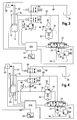
- FIG. 1 shows a hydraulic cylinder 10 with a hydraulic piston 12 which serves to raise and lower a boom of a loader vehicle (both not shown).
- the hydraulic cylinder 10 has a lifting-side chamber 14 and a lowering-side chamber 16.
- the lift-side chamber 14 is connected via a stroke-side hydraulic line 18 and the lower-side chamber 16 via a vertical hydraulic line 20 with an electrically switchable control valve 22.
- the control valve 22 is connected via a drain line 24 and via a pressure limiting line 26 with a hydraulic oil tank 28.
- a hydraulic oil pump 30 delivers hydraulic oil via the control valve 22 into the respective hydraulic lines 18, 20.
- the control valve 22 is switchable in three positions, in a closed position, in which no flow for both hydraulic lines 18, 20 takes place, a stroke position in which the stroke-side hydraulic line 18 is supplied with hydraulic oil, wherein the vertical-side hydraulic line 20 emits hydraulic oil to the hydraulic tank 28 , and a lowering position, in which the vertical-side hydraulic line 20 is supplied with hydraulic oil, wherein the stroke-side hydraulic line 18 emits hydraulic oil to the hydraulic tank 28.
- the pressure limiting line 26 contains a pressure limiting valve 32 which opens when a limiting pressure is reached and allows a flow from the hydraulic oil pump 30 to the hydraulic oil tank 28.
- the hydraulic oil pump 30 can promote hydraulic oil in this way even when the control valve 22 is closed.
- the lift-side hydraulic line 18 contains a load-holding valve 34, which allows a hydraulic oil flow in the direction of the hydraulic cylinder 10 via a bypass line 36. Via control lines 38, the load-holding valve is opened in the direction of the hydraulic oil tank 28 in the event of an overload, so that a hydraulic oil flow to the hydraulic oil tank 28 can take place.
- a connecting line 40 is arranged, which contains an electrically switchable first check valve 42.
- the first check valve contains a blocking position in which there is no flow in both directions and an open position in which a flow is possible in both directions.
- the connecting line 40 contains a controllable pressure limiting valve 44, which opens via a control line 46 in the direction of the vertical hydraulic line 20.
- the control pressure for opening the pressure limiting valve can be regulated via a regulator 48.
- a position sensor 50 is connected to a piston rod 52 of the hydraulic cylinder 10 and provides a sensor signal representing the position of the hydraulic piston 12 to a control unit 54.
- the control unit 54 is connected to a switching device 56, via which the control unit 54 and thus the hydraulic suspension are activated can.
- the hydraulic active suspension is realized with a constantly flowing volume flow.
- the control unit 54 is activated via the switching device 56, wherein the control unit 54, the first check valve 42 opens and the control valve 22 switches to the stroke position.
- the Hydraulic oil pump 30 delivers the hydraulic oil via the control valve 22 and via the load-holding valve 34 to the hydraulic cylinder 10 of the boom. There, a certain pressure builds up, which is adjusted by means of the controllable pressure limiting valve 44. As soon as a pressure equilibrium has been established, the hydraulic piston 12 assumes a specific position, wherein excess hydraulic oil delivered by the hydraulic oil pump flows via the pressure limiting valve 44 and via the first shut-off valve 42 to the hydraulic tank.
- the basic operating principle is that the pressure on the lifting side of the hydraulic cylinder 10 is controlled by a certain inflow of hydraulic oil controlled to the hub side can flow to the hydraulic tank 28 again.
- the pressure is generated such that the hydraulic oil can flow to the hydraulic tank 28 only against a certain resistance which is predetermined by the pressure limiting valve 44, this pressure being so high that it can counteract a load which acts on the hydraulic cylinder 10 ,
- the check valve 42 must be switched to its open position. If this is not the case, a pressure builds up on the lifting side of the hydraulic cylinder 10 and thus in the lifting-side chamber 14, which extends the piston and thus causes the boom to rise. About the controllable pressure relief valve 44, the pressure which is to prevail on the stroke side of the hydraulic cylinder 10, adjusted as needed by the control unit 54.
- the position of the arm or the position of the piston rod 52 and the hydraulic piston 12 is continuously measured via the position sensor 50 and serves as a controlled variable (actual value) for adjusting the pressure on the stroke side of the hydraulic cylinder 10.
- This position can be measured in different ways and Wise. One way is shown in Figure 1, in which the position of the piston rod 52 is tapped. Also suitable would be the lifting angle of the boom.
- control unit 54 Upon activation of the control unit 54, the control is activated and the original position of the boom as maintained reference variable (setpoint) recorded.
- the control unit 54 determines via an integrated processor (not shown) from the reference variable and the current measured controlled variable (actual value) the deviation (control difference) from each other to make on this basis, the adjustment of the pressure relief valve 44 by means of a manipulated variable.
- the pressure limiting valve 44 is set to a higher value, so that the pressure on the lifting side of the hydraulic cylinder 10 increases and the hydraulic piston 12 is extended.
- control unit 54 determines that the boom has been lifted too high, the pressure limiting valve 44 is reduced to a lower value, so that the pressure on the lifting side of the hydraulic cylinder is reduced and the hydraulic cylinder is retracted.
- accelerations shocks and vibrations
- the acceleration generated by the mass of the boom a force that transmits as a disturbance to the hydraulic cylinder 10 and thus displaces or relieves the hydraulic oil on the stroke side of the hydraulic cylinder 10.
- the oil from the stroke side of the hydraulic cylinder 10 is displaced by the hydraulic piston 12 and flows through the pressure relief valve 44 from. Due to the displaced hydraulic oil volume of the boom decreases, which in turn is detected as a control difference from the control unit 54, whereupon the control unit increases the opening pressure of the pressure relief valve 44 by the control unit 54 determines the manipulated variable according to the control difference. Due to the increase in the opening pressure and the constant flow of control valve 22 volumetric flow, the boom is raised again until the control difference has decreased again to zero or to a presettable threshold.
- a shock which can extend the hydraulic piston 12
- the hydraulic oil is relieved on the stroke side of the hydraulic cylinder 10 by the movement of the hydraulic piston 12 and an increase in volume of the stroke-side chamber 14 occurs.
- the constantly flowing volume flow of control valve 22 fills this volume increase, so that the hydraulic cylinder 10 can extend without the risk of generating a vacuum occurs.
- a control difference is detected by the control unit 54, whereupon the control unit 54 the opening pressure of the pressure relief valve 44 is reduced by the control unit 54 determines the corresponding manipulated variable according to the control difference. Due to the reduction in the opening pressure, hydraulic oil flows from the lift side of the hydraulic cylinder 10 via the pressure relief valve 44 and the boom lowers until the control difference has decreased to zero or to a presettable threshold.
- control valve 22 is additionally variably changed in its opening cross section depending on the current demand, so that more volume flow can flow to the hydraulic cylinder 10. In extreme cases, a reversal of the volume flow direction would also be conceivable by a lowering, to retract the hydraulic piston 12 faster.
- control valve 22 may be electrical, pneumatic or otherwise. It is also conceivable that the controllable pressure limiting valve 44 is controlled pneumatically or hydraulically and not as shown in Figure 1 electrically. This can be advantageous at high pressures and / or high volume flows, since then very high forces must be applied by the adjusting mechanism.
- an electrically variable throttle 58 can be used instead of the electrically controllable pressure relief valve 44, as shown in Figure 2, an electrically variable throttle 58 can be used. However, the basic principle of action remains the same.
- the hydraulic oil flowing through the lift-side line constantly flows through the throttle 58 to the hydraulic tank 28 when the check valve 42 is open.
- a specific pressure drop across the throttle 58 which depends on the volume flow and the opening cross section of the throttle 58, so that on the stroke side of the hydraulic cylinder 10, a certain dynamic pressure is created, which prevents sagging of the boom.
- the height of the back pressure can be changed via the volume flow from the control valve 22 or via the controllable opening cross section of the throttle 58.
- the position of the boom is also constantly measured and used as a control variable (actual value) for adjusting the back pressure on the stroke side of the hydraulic cylinder 10.
- This position can also be measured in different ways. It would be conceivable, as shown in Figure 2, the position of the piston rod 52 or the lifting angle of the boom.
- control unit 54 If the control is activated, the control unit 54, analogous to the example of FIG. 1, generates a manipulated variable with which the opening cross-section of the throttle 58 is regulated via a throttle controller 60 and / or a change in the volume flow is caused by the control valve 22.
- the opening cross section of the throttle 58 is set to a smaller value, so that the dynamic pressure increases on the lifting side of the hydraulic cylinder 10 and the hydraulic piston 12 is extended. Also, in this case, either only or simultaneously Volume flow can be increased by the control valve 22 to increase the back pressure.
- the opening area of the throttle 58 is set to a higher value so that the back pressure on the lift side of the hydraulic cylinder 10 decreases and the hydraulic piston 12 is retracted. Also, in this case, either only or simultaneously, the volume flow from the control valve 22 can be reduced in order to reduce the back pressure.
- a shock which can extend the hydraulic cylinder 10
- the hydraulic oil is relieved on the lift side of the hydraulic cylinder 10 by the movement of the hydraulic piston 12 and an increase in volume of the stroke-side chamber 14 occurs.
- the constantly flowing volume flow of control valve 22 fills the increase in volume, so that the hydraulic piston 12 can extend without the risk of generating a vacuum occurs.
- the boom lifts which in turn is detected by the control unit 54 as a control difference, whereupon the control unit 54 increases the opening cross section of the throttle 58 by the control unit 54 determines the manipulated variable corresponding to the control difference. Due to this reduction of the dynamic pressure, more hydraulic oil flows from the lifting side of the hydraulic cylinder 10 via the throttle 58 as volume flow from the control valve 22 can flow.
- the boom lowers until the control difference has returned to zero or to a presettable threshold.
- the electrically controllable throttle 58, as well as the first check valve 42 or the control valve 22, are controlled pneumatically or hydraulically.
- a second vertical line 62 is provided, which leads from the first vertical line 20 to the hydraulic tank 28 and is provided with a second check valve 64, wherein the first and the second check valve 42nd , 64 may be identical.
- FIGS. 3 and 4 are demand-controlled suspension systems, in which, in contrast to the exemplary embodiments illustrated in FIGS. 1 and 2, only a volume flow from the control valve 22 via a load-holding valve 34 to the hydraulic cylinder 10 of the delivery arm is required flows.
- the control valve 22 is thus in the closed position and is switched as needed by the control unit 54 in the corresponding other positions.
- FIG. 3 shows the demand-controlled hydraulic suspension with the electrically controllable pressure limiting valve 44, as can also be seen in FIG.
- control unit 56 If the control is activated by the switching unit 56, the original position of the boom is held as the reference variable to be observed and the control unit determines from this command variable and the current, measured position (control variable) the deviation (control difference) from each other, on this basis, the scheme perform the pressure limiting valve 44 and adjust the height of the flow rate of the control valve 22 by means of further control variables.
- the pressure on the stroke side of the hydraulic cylinder 10th should act, as required regulated by the control unit 54.
- the pressure relief valve 44 is set to a higher value and the control valve 22 is opened, so that increased by the flowing volume of the pressure on the lifting side of the hydraulic cylinder 10 and the hydraulic cylinder 10 extended becomes.
- the pressure limiting valve 44 is set to a lower value, so that the pressure on the lifting side of the hydraulic cylinder 10 is reduced and the hydraulic piston 12 is retracted.
- the hydraulic oil which then flows from the lift side of the hydraulic cylinder 10 via the pressure limiting valve 44 and the first check valve 42 to the lowering side of the hydraulic cylinder 10, flows from there via the second check valve 64 to the hydraulic tank 28.
- the hydraulic oil from the stroke side of the hydraulic cylinder 10 is displaced by the hydraulic piston 12 and flows through the pressure relief valve 44 and via the check valves 42, 64 from. Due to the displaced oil volume of the boom decreases, which in turn is detected as a control difference from the control unit 54, whereupon the control unit 54 increases the opening pressure of the pressure relief valve 44 and the control valve 22 in the stroke position, so that a flow to the stroke side of the hydraulic cylinder 10 flows the manipulated variables are determined by the control unit 54 according to the control difference. Due to the increase of the opening pressure and of the Control valve 22 flowing volume flow, the boom is raised again until the control difference has reduced back to zero or to a presettable threshold.
- control unit 54 switches the control valve 22 back into the closed position. Due to the reduction in the opening pressure, hydraulic oil flows from the lift side of the hydraulic cylinder 10 via the pressure relief valve 44 and the boom lowers until the control difference has decreased to zero or to a presettable threshold.
- control valves 22 and check valves 42, 64 shown in Figures 1 to 4 are shown electrically switchable, but can also be controlled pneumatically, hydraulically or in another way.
- FIG. 2 Another embodiment is shown in FIG. The difference from the previous exemplary embodiment illustrated in FIG. 3 is that, as also shown in FIG. 2, an adjustable throttle 58 is used instead of the controllable pressure limiting valve 44.
- a pressure sensor 66 is arranged on the lift side of the hydraulic cylinder 10, which is required to deliver an opening signal for the check valves 42, 64 to the control unit 54.
- other types of acceleration measuring devices with the aid of which the loads on the hydraulic cylinder 10 can be measured, can be used.
- the measurement of the load on the hydraulic cylinder 10 is required to determine when the check valves 42, 64 must be opened, otherwise via the variable throttle 58, the hydraulic oil from the lift side of the hydraulic cylinder 10 can flow and the boom would drop.
- the load of the hydraulic cylinder 10 is measured directly via the pressure sensor 66 or alternatively indirectly via an acceleration sensor. This load is recorded together with the original position of the boom as the reference variable to be observed.
- control unit 54 If the control unit 54 now determines a certain deviation of the hydraulic cylinder load, the control unit 54 opens the control valve 22 and the two check valves 42, 64 so that a volume flow can flow. Due to the throttling, this volume flow generates such a dynamic pressure on the lifting side of the hydraulic cylinder 10 that the load acting on the hydraulic cylinder 10 is borne.
- the control unit 54 determines one or more manipulated variables in the presence of control deviation in order to adjust the opening cross section of the throttle 58 and / or the change in the volume flow of the control valve 22. If the control unit 54 determines that the boom has fallen too low after opening the control valve 22 and the check valves 42, 64, the opening cross section of the throttle becomes 58 is set to a smaller value, so that the dynamic pressure increases on the lifting side of the hydraulic cylinder 10 and the hydraulic piston 12 is extended.
- the opening area of the throttle 58 is set to a larger value, so that the back pressure on the lift side of the hydraulic cylinder 10 decreases and the hydraulic piston 12 is retracted.
- the control unit 54 In a shock, which exerts a force on the lift-side chamber 14, the control unit 54 generates a manipulated variable due to the opening signal by the pressure sensor 66, which leads to the opening of the control valve 22 and the check valves 42, 64, so that the hydraulic piston 12 can retract ,
- the hydraulic oil from the lifting side of the hydraulic cylinder 10 is displaced by the hydraulic piston 12 and flows through the throttle 58 and the check valves 42, 64 from. Due to the displaced hydraulic oil volume of the boom decreases, which in turn is recognized as a control difference from the controller, whereupon the control unit 54 reduces the opening cross-section of the throttle 58. Due to the resulting increase in the dynamic pressure and the volume flow flowing through control valve 22, the boom is raised again until the control difference has reduced again to zero or to a presettable threshold value.
- the control unit 54 In a shock, which exerts a force on the lower-side chamber 16, the control unit 54 generates a manipulated variable due to the opening signal by the pressure sensor 66, which leads to the opening of the control valve 22 and the check valves 42, 64, so that the hydraulic piston 12 can extend .
- the hydraulic oil is relieved on the stroke side of the hydraulic cylinder 10 and an increase in volume of the stroke-side chamber 14 occurs because oil is displaced from the lower-side chamber 16 to the hydraulic tank 28 out.
- This raising of the boom is detected by the control unit 54 as a control difference and the control valve 22 is opened to fill by means of a volume flow, the resulting increase in volume on the stroke side of the hydraulic cylinder 10.
- FIGS 5 to 7 show simplified embodiments of the invention, which substantially correspond to the embodiments described in Figures 1 and 2, except that the first check valve is omitted.
- Figure 5 shows the simplest of the illustrated embodiments, in comparison to Figure 1, the first check valve 42 has been saved.
- the pressure limiting valve 44 shown in FIG. 5 is then regulated to a correspondingly high pressure limiting value when the suspension is not activated, so that the connecting line 40 is essentially closed, in a manner similar to that which would be achieved by a blocking valve 42. Only when the suspension is activated, the pressure limiting valve 44 is downshifted by the control unit 54 to a control range, which essentially corresponds to a control range corresponding to the functional principle with respect to Figure 1.
- the procedure for the exemplary embodiment in FIG. 1 is analogous to the previously described functional principle.
- a check valve 68 may preferably be used, as shown in Figure 6.
- FIG. 7 A further exemplary embodiment is illustrated in FIG. 7, in which, in comparison to FIG. 2, the first check valve 42 has been replaced by a check valve 68.
- This Embodiment represents in comparison to the embodiment of Figure 2 is a variant with the switching operations for the first check valve 42 can be saved.
- the throttle 58 shown in Figure 7 is then regulated at non-activated suspension to a correspondingly small, a high back pressure generating passage cross section or closed accordingly, so that the passage cross section of the throttle is substantially zero and the connecting line 40 is substantially closed, similar how it would cause a check valve 42.
- the throttle 58 is controlled by the control unit 54 to a control range with a larger, a lower back pressure generating, passage cross-section or opened accordingly, the control range substantially corresponds to a control range according to the principle of operation with respect to Figure 2.
- the check valve 68 is in this case necessary to prevent an inflow in the direction of the stroke-side chamber 14 through the connecting line 40 with activated suspension, since a throttle 58 or aperture is permeable in both directions.
- leaks in the direction of the stroke-side chamber 14 can occur at the throttle 58 with deactivated suspension, which can be avoided by the check valve 68.
- the check valve 68 thus also contributes to a proper function of the load-holding valve 34. In a hydraulic suspension without load-holding valve 34 could be dispensed with the check valve 68, since then hydraulic oil can always flow from the hub Carnegieen chamber.
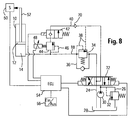
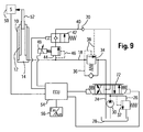
- FIGS. 8 and 9 show exemplary embodiments of single-acting lifting cylinders 10. It can be seen in FIG. 8 that it is essentially the hydraulic circuit of FIG. Since a single-acting hydraulic cylinder 10 is used here, the hydraulic line 20 is omitted, so that the connecting line 40 now connects the stroke-side chamber 14 of the hydraulic cylinder 10 with a control valve 72 or via the control valve 72 with the hydraulic oil tank 28.
- the control valve 72 is designed such that it connects the connection line 40 with the hydraulic oil pump 30 and the lift-side hydraulic line 18 with the hydraulic oil tank 28 in the lowered position.
- a check valve 70 is provided behind the connection to the control line 38 in the connecting line 40. Only by the check valve 70, the hydraulic cylinder 10 can be lowered.
- the control valve 72 is brought to the lowering position, whereby the hydraulic oil pump 30 generates an opening pressure in the control line 38 due to the closing in the pump delivery direction check valve 70, so that the load-holding valve 34 is opened and the hydraulic oil from the chamber 14 through the lift-side hydraulic line 18 into the hydraulic oil tank 28th can drain away.
- the check valve 42 is adapted to the configuration with a single-acting lifting cylinder 10, since only one hydraulic oil flow in one direction is to be expected here. Analogously to this, the changes can also be made in conjunction with the hydraulic circuits shown in FIGS. 2 and 5 to 7, so that the use of a single-acting hydraulic cylinder 10 in the exemplary embodiments illustrated in FIGS. 2 and 5 to 7 is likewise possible.
- a telescopic cylinder is arranged as a hydraulic cylinder 10 in FIG.
- the operation of the suspension is not affected. It should only be shown with reference to FIG. 9 that telescoping hydraulic cylinders 10 can also be used.
- the hydraulic active suspension for a single-acting hydraulic cylinder 10 can be realized both with a constantly flowing volume flow and with an on-demand flow rate.
- the control unit 54 is activated via the switching device 56, wherein the control unit 54 opens the check valve 42 and the control valve 72 switches to the stroke position in which the hydraulic oil pump 30 is connected to the lift-side hydraulic line 18.
- the hydraulic oil pump 30 delivers the hydraulic oil via the control valve 72 and via the load-holding valve 34 to the hydraulic cylinder 10 of the boom. There, a certain pressure builds up, which is adjusted by means of the controllable pressure limiting valve 44.
- the hydraulic piston 12 assumes a specific position, wherein excess hydraulic oil delivered by the hydraulic oil pump 30 flows in the connecting line 40 via the pressure limiting valve 44 and via the first shut-off valve 42 and via the check valve 70 to the hydraulic tank 28. If it now happens with activated suspension (check valve 42 is open) for compression of the hydraulic piston 12, generated the control unit 54 on the basis of the signal of the position sensor 50, a control signal for the pressure limiting valve 44, which then increase the pressure in the lift-side hydraulic line 18 until the hydraulic piston 12 has again assumed its initial position.
- the basic mode of action therefore also corresponds to a simple-acting hydraulic cylinder 10, whether conventional or designed as a telescopic cylinder, the principle described in Figure 1, so that the pressure in the stroke-side chamber 14 of the single-acting hydraulic cylinder 10 is controlled by a certain inflow of hydraulic oil to the lifting side (to the chamber 14) controlled to the hydraulic tank 28 can flow through the connecting line 40.
- a simple-acting hydraulic cylinder 10 whether conventional or designed as a telescopic cylinder, the principle described in Figure 1, so that the pressure in the stroke-side chamber 14 of the single-acting hydraulic cylinder 10 is controlled by a certain inflow of hydraulic oil to the lifting side (to the chamber 14) controlled to the hydraulic tank 28 can flow through the connecting line 40.
- the control valve 72 is switched after lifting or lowering of the hydraulic cylinder 10 (via the lifting or lowering position of the control valve 72) in its middle position in which both the hydraulic line 18 and the connecting line 40 with the hydraulic oil tank 28th get connected. In this position, no hydraulic oil flows through the lines 18 and 40 from the hydraulic oil pump 30. If the suspension is activated (check valve 42 is open), for example due to shocks, an increase in pressure in the lift-side chamber 14 occurs with a drop or compression of the piston Hydraulic piston 12 is connected, this is detected by the position sensor 50. The control unit 54 registers the change and generates a control signal by which the Control valve 72 is switched to its stroke position. This is followed by the renewed lifting of the hydraulic piston 10 until the starting position of the hydraulic piston 10 is reached again. As soon as the starting position is reached, the control unit 54 switches the control valve 72 back to the middle position.
Landscapes
- Engineering & Computer Science (AREA)
- Mechanical Engineering (AREA)
- Structural Engineering (AREA)
- Transportation (AREA)
- General Engineering & Computer Science (AREA)
- Fluid Mechanics (AREA)
- Physics & Mathematics (AREA)
- Chemical & Material Sciences (AREA)
- Civil Engineering (AREA)
- Analytical Chemistry (AREA)
- Life Sciences & Earth Sciences (AREA)
- Geology (AREA)
- Mining & Mineral Resources (AREA)
- Combustion & Propulsion (AREA)
- Fluid-Pressure Circuits (AREA)
- Vehicle Body Suspensions (AREA)
- Fluid-Damping Devices (AREA)
Claims (13)
- Suspension hydraulique, en particulier pour un bras d'une chargeuse, comportant au moins un vérin hydraulique (10), qui comporte au moins une chambre (14, 16), une vanne pilote (22), qui est reliée à ladite au moins une chambre (14, 16) par l'intermédiaire d'au moins une conduite hydraulique (18, 20) et qui établit au choix une liaison vers une pompe à huile hydraulique (30) et vers un réservoir d'huile hydraulique (28), et une conduite de liaison (40), caractérisée en ce qu'il est prévu une unité de commande (54) et un capteur (50) indiquant la position du vérin hydraulique (10) et en ce que la conduite de liaison (40) comporte une unité de limitation de pression (44, 58) réglable en fonction du signal du capteur.
- Suspension hydraulique selon la revendication 1, caractérisée en ce que la conduite de liaison (40) relie ladite au moins une chambre (14, 16) avec le réservoir d'huile hydraulique (28).
- Suspension hydraulique selon les revendications 1 et 2, caractérisée en ce que le vérin hydraulique (10) comporte une chambre (14) du côté levage et une chambre (16) du côté abaissement, qui communiquent l'une avec l'autre via la conduite de liaison (40) et la vanne pilote est reliée aux chambres (14, 16) via une première conduite (20) du côté abaissement et via une conduite (18) du côté levage.
- Suspension hydraulique selon l'une quelconque des revendications précédentes, caractérisée en ce que la conduite de liaison (40) comporte une première vanne de fermeture (42), qui par son ouverture et sa fermeture active et désactive la suspension hydraulique.
- Suspension hydraulique selon l'une quelconque des revendications 3 à 4, caractérisée en ce que la conduite de liaison (40) comporte un clapet anti-retour (68) qui ferme vers la chambre (14) du côté levage.
- Suspension hydraulique selon l'une quelconque des revendications précédentes, caractérisée en ce que l'unité de limitation de pression est un limiteur de pression (44) réglable.
- Suspension hydraulique selon l'une quelconque des revendications 1 à 5, caractérisée en ce que l'unité de limitation de pression est un étranglement (58) réglable.
- Suspension hydraulique selon l'une quelconque des revendications précédentes, caractérisée en ce que la vanne pilote (22) a une position de fermeture.
- Suspension hydraulique selon l'une quelconque des revendications précédentes, caractérisée en ce qu'une vanne de maintien en charge (34) est agencée dans ladite au moins une conduite hydraulique (18, 20).
- Suspension hydraulique selon l'une quelconque des revendications précédentes, caractérisée en ce qu'une conduite de limitation de pression (26), munie d'un limiteur de pression (32) et reliée au réservoir hydraulique (28), est montée entre la pompe hydraulique (30) et la vanne pilote (22).
- Suspension hydraulique selon l'une quelconque des revendications précédentes, caractérisée en ce que l'unité de commande (54) règle l'unité de limitation de pression (44, 58) réglable en fonction d'un signal de différence résultant du signal de capteur variable et d'un signal de valeur de consigne, le signal de valeur de consigne correspondant au signal de capteur lors de l'activation de la suspension hydraulique et le signal de différence atteignant une valeur seuil prédéfinissable.
- Suspension hydraulique selon l'une quelconque des revendications 3 à 11, caractérisée en ce qu'il est prévu une deuxième conduite (62) du côté abaissement avec une deuxième vanne de fermeture (64), qui relie la chambre (16) du côté abaissement avec le réservoir hydraulique (28).
- Suspension hydraulique selon l'une quelconque des revendications précédentes, caractérisée en ce que le vérin hydraulique (10) comporte des moyens de mesure de charge, en particulier un capteur de pression (66).
Applications Claiming Priority (4)
| Application Number | Priority Date | Filing Date | Title |
|---|---|---|---|
| DE10330344 | 2003-07-05 | ||
| DE2003130344 DE10330344A1 (de) | 2003-07-05 | 2003-07-05 | Hydraulische Federung |
| DE10343742 | 2003-09-22 | ||
| DE10343742 | 2003-09-22 |
Publications (2)
| Publication Number | Publication Date |
|---|---|
| EP1496009A1 EP1496009A1 (fr) | 2005-01-12 |
| EP1496009B1 true EP1496009B1 (fr) | 2007-09-05 |
Family
ID=33453881
Family Applications (1)
| Application Number | Title | Priority Date | Filing Date |
|---|---|---|---|
| EP04103115A Expired - Lifetime EP1496009B1 (fr) | 2003-07-05 | 2004-07-01 | Suspension hydraulique |
Country Status (5)
| Country | Link |
|---|---|
| US (1) | US6988363B2 (fr) |
| EP (1) | EP1496009B1 (fr) |
| AT (1) | ATE372296T1 (fr) |
| DE (1) | DE502004004847D1 (fr) |
| ES (1) | ES2289436T3 (fr) |
Cited By (1)
| Publication number | Priority date | Publication date | Assignee | Title |
|---|---|---|---|---|
| CN108328524A (zh) * | 2017-01-17 | 2018-07-27 | 雷蒙德股份有限公司 | 用于物料搬运车辆的可变液压压力卸载系统和方法 |
Families Citing this family (45)
| Publication number | Priority date | Publication date | Assignee | Title |
|---|---|---|---|---|
| JP2004348650A (ja) * | 2003-05-26 | 2004-12-09 | Toshiba Corp | 電子機器 |
| US7130721B2 (en) * | 2004-10-29 | 2006-10-31 | Caterpillar Inc | Electrohydraulic control system |
| DE102004056418B4 (de) * | 2004-11-23 | 2013-02-28 | Deere & Company | Hydraulische Anordnung |
| DE102005021887A1 (de) * | 2005-05-04 | 2006-11-16 | Kässbohrer Geländefahrzeug AG | Verfahren sowie Vorrichtung zur Fahrstabilitätserhöhung von Kraftfahrzeugen |
| DE102005038333A1 (de) * | 2005-08-11 | 2007-02-15 | Deere & Company, Moline | Hydraulische Anordnung |
| DE102005039251A1 (de) | 2005-08-19 | 2007-02-22 | Deere & Company, Moline | Ladegerät |
| DE102005043447A1 (de) | 2005-09-13 | 2007-03-15 | Deere & Company, Moline | Ladegerät sowie Verfahren für ein Ladegerät |
| DE102005059240A1 (de) * | 2005-12-12 | 2007-06-14 | Linde Ag | Hydrostatisches Antriebssystem |
| SE531309C2 (sv) * | 2006-01-16 | 2009-02-17 | Volvo Constr Equip Ab | Styrsystem för en arbetsmaskin och förfarande för styrning av en hydraulcylinder hos en arbetsmaskin |
| JP4353190B2 (ja) * | 2006-02-27 | 2009-10-28 | コベルコ建機株式会社 | 建設機械の油圧回路 |
| DE102006042372A1 (de) * | 2006-09-08 | 2008-03-27 | Deere & Company, Moline | Ladegerät |
| US7845169B2 (en) * | 2006-10-17 | 2010-12-07 | Caterpillar Inc | Drift compensation control method for a machine |
| US8204653B2 (en) * | 2007-02-21 | 2012-06-19 | Deere & Company | Automated control of boom and attachment for work vehicle |
| JP5064843B2 (ja) * | 2007-03-08 | 2012-10-31 | 株式会社小松製作所 | 作業機ポンプの回転制御システム |
| DE102007051857B3 (de) * | 2007-10-30 | 2009-04-23 | Siemens Ag | Regeleinrichtung zum Positionsregeln einer Hydraulikzylindereinheit mit Linearisierungseinheit |
| RU2453658C2 (ru) * | 2007-11-21 | 2012-06-20 | Вольво Констракшн Эквипмент Аб | Чувствительная к нагрузке система, содержащая её рабочая машина и способ управления гидроприводом |
| WO2009067050A1 (fr) * | 2007-11-21 | 2009-05-28 | Volvo Construction Equipment Ab | Système de détection de charge, machine d'usinage comprenant le système et procédé pour commander une fonction hydraulique |
| US9932721B2 (en) | 2007-11-21 | 2018-04-03 | Volvo Construction Equipment Ab | System, working machine comprising the system, and method of springing an implement of a working machine during transport |
| US20140026548A1 (en) | 2011-04-15 | 2014-01-30 | Volvo Construction Equipment Ab | Method and a device for reducing vibrations in a working machine |
| US9187297B2 (en) * | 2011-05-13 | 2015-11-17 | Kabushiki Kaisha Kobe Seiko Sho | Hydraulic driving apparatus for working machine |
| JP6305996B2 (ja) * | 2012-06-22 | 2018-04-04 | エボリュート・ドライヴズ・リミテッド | 変速機システム |
| DE102012106185B3 (de) * | 2012-07-10 | 2013-11-21 | Fsp Fluid Systems Partners Holding Ag | Steueranordnung für ein hydropneumatisches Federungssystem sowie hydropneumatisches Federungssystem mit einer solchen Steueranordnung |
| US8833481B2 (en) * | 2012-09-06 | 2014-09-16 | Cnh Industrial America Llc | System for controlling wing tool bars of an agricultural implement having an angle sensor |
| DE102012022030A1 (de) * | 2012-11-12 | 2014-05-15 | Deere & Company | Federungseinrichtung für eine beweglich gelagerte Fahrzeugachse |
| JP5661085B2 (ja) | 2012-11-13 | 2015-01-28 | 株式会社神戸製鋼所 | 作業機械の油圧駆動装置 |
| JP5661084B2 (ja) * | 2012-11-13 | 2015-01-28 | 株式会社神戸製鋼所 | 作業機械の油圧駆動装置 |
| US9204626B2 (en) * | 2013-10-23 | 2015-12-08 | Ms Gregson | Method and system for controlling an inclination of a boom carried by a vehicle |
| EP3306283B1 (fr) * | 2015-05-26 | 2020-12-23 | Hitachi Construction Machinery Co., Ltd | Dispositif de mesure de charge pour machine de construction |
| EP3196623A1 (fr) * | 2016-01-25 | 2017-07-26 | Primetals Technologies Germany GmbH | Detection simple de fuite dans une unite de verin hydraulique |
| US11357177B2 (en) * | 2017-08-03 | 2022-06-14 | Firefly Automatix, Inc. | Sod harvester hydraulic system for actuating components with precise timing |
| DE102018104586A1 (de) * | 2018-02-28 | 2019-08-29 | Jungheinrich Aktiengesellschaft | Flurförderzeug mit mindestens einem hydraulischen Masthubzylinder |
| US10724209B2 (en) | 2018-04-13 | 2020-07-28 | Deere & Company | Adjustable work implement |
| JP2019199881A (ja) * | 2018-05-14 | 2019-11-21 | 株式会社神戸製鋼所 | 作業機械の油圧駆動装置 |
| US10760599B2 (en) | 2018-06-29 | 2020-09-01 | Kti Hydraulics Inc. | Power units with manual override controls for hydraulic systems |
| DE102019209091A1 (de) * | 2019-06-24 | 2020-12-24 | Festo Se & Co. Kg | Verfahren zum Betreiben eines Fluidsystems, Fluidsystem und Computerprogrammprodukt |
| CN110319242B (zh) * | 2019-08-05 | 2024-03-26 | 安徽理工大学 | 一种基于双向扭转弹簧的旋转阀芯切换机构 |
| US11408144B2 (en) | 2019-08-29 | 2022-08-09 | Deere & Company | Variable float and variable blade impact |
| CN112010166B (zh) * | 2020-08-26 | 2022-09-06 | 江苏金风科技有限公司 | 叶片吊装工装及其液压系统 |
| ZA202110395B (en) * | 2020-12-30 | 2023-11-29 | Manitou Italia Srl | Telehandler with facilitated alignment adjustment |
| CN113007159B (zh) * | 2021-02-09 | 2023-03-10 | 中国煤炭科工集团太原研究院有限公司 | 液压张紧方法、液压张紧装置和连续采煤机 |
| US12428811B2 (en) * | 2021-11-19 | 2025-09-30 | Robert Bosch Gmbh | Construction machine with active ride control |
| DE102022124970A1 (de) * | 2022-09-28 | 2024-03-28 | Deere & Company | Anordnung zur Steuerung eines hydraulischen Dreipunkt- Krafthebers |
| DE102022124969A1 (de) | 2022-09-28 | 2024-03-28 | Deere & Company | Anordnung zur Steuerung eines hydraulischen Dreipunkt- Krafthebers |
| EP4365023B1 (fr) | 2022-11-07 | 2025-09-17 | Hiab AB | Équipement de travail ayant des capacités d'empêcher le flambage d'un cylindre hydraulique |
| EP4585433A1 (fr) * | 2024-01-09 | 2025-07-16 | Volvo Construction Equipment AB | Système de suspension à base de fluide d'un véhicule |
Family Cites Families (17)
| Publication number | Priority date | Publication date | Assignee | Title |
|---|---|---|---|---|
| US4643074A (en) * | 1985-03-07 | 1987-02-17 | Vickers, Incorporated | Power transmission |
| EP0378129B1 (fr) * | 1989-01-13 | 1994-11-30 | Hitachi Construction Machinery Co., Ltd. | Système hydraulique pour le vérin de la flèche d'une machine de construction |
| JPH0662268B2 (ja) * | 1989-04-21 | 1994-08-17 | 株式会社神戸製鋼所 | 移動式クレーンの変位抑制装置 |
| JPH0815998B2 (ja) * | 1989-10-14 | 1996-02-21 | 株式会社神戸製鋼所 | ホイール式クレーンの振動抑制装置 |
| DE4105459A1 (de) | 1991-02-21 | 1992-08-27 | Heilmeier & Weinlein | Hydraulische steuervorrichtung |
| DE4221943C2 (de) * | 1991-09-04 | 1996-01-25 | Orenstein & Koppel Ag | Hydraulikanlage für mit Arbeitsgeräten versehene fahrbare Arbeitsmaschinen |
| DE4129509C2 (de) | 1991-09-05 | 1994-06-16 | Rexroth Mannesmann Gmbh | Hydraulische Steueranordnung für Baumaschinen |
| DE4231399A1 (de) | 1992-08-20 | 1994-02-24 | Rexroth Mannesmann Gmbh | Hydraulische Steuereinrichtung |
| DE4402580B4 (de) | 1994-01-28 | 2006-12-14 | Linde Ag | Hydraulisches Antriebssystem |
| JPH0812546A (ja) | 1994-06-30 | 1996-01-16 | Toray Dow Corning Silicone Co Ltd | 日焼け防止用化粧料 |
| US5666806A (en) * | 1995-07-05 | 1997-09-16 | Caterpillar Inc. | Control system for a hydraulic cylinder and method |
| US5622226A (en) * | 1996-01-29 | 1997-04-22 | Caterpillar Inc. | Method for controlling bounce of a work implement |
| JP3501902B2 (ja) * | 1996-06-28 | 2004-03-02 | コベルコ建機株式会社 | 建設機械の制御回路 |
| US5890870A (en) | 1996-09-25 | 1999-04-06 | Case Corporation | Electronic ride control system for off-road vehicles |
| DE10006908A1 (de) | 2000-02-16 | 2001-08-23 | Caterpillar Sarl Genf Geneva | Hydraulische Kolbenzylindereinheit für landwirtschaftliche Arbeitsmaschinen |
| US6422804B1 (en) | 2000-02-18 | 2002-07-23 | Deere & Company | Inertia load dampening hydraulic system |
| DE10046546A1 (de) | 2000-09-19 | 2002-03-28 | Putzmeister Ag | Großmanipulator mit Schwingungsdämpfer |
-
2004
- 2004-07-01 DE DE502004004847T patent/DE502004004847D1/de not_active Expired - Lifetime
- 2004-07-01 ES ES04103115T patent/ES2289436T3/es not_active Expired - Lifetime
- 2004-07-01 AT AT04103115T patent/ATE372296T1/de not_active IP Right Cessation
- 2004-07-01 EP EP04103115A patent/EP1496009B1/fr not_active Expired - Lifetime
- 2004-07-02 US US10/884,716 patent/US6988363B2/en not_active Expired - Fee Related
Cited By (1)
| Publication number | Priority date | Publication date | Assignee | Title |
|---|---|---|---|---|
| CN108328524A (zh) * | 2017-01-17 | 2018-07-27 | 雷蒙德股份有限公司 | 用于物料搬运车辆的可变液压压力卸载系统和方法 |
Also Published As
| Publication number | Publication date |
|---|---|
| EP1496009A1 (fr) | 2005-01-12 |
| ATE372296T1 (de) | 2007-09-15 |
| ES2289436T3 (es) | 2008-02-01 |
| US20050011190A1 (en) | 2005-01-20 |
| DE502004004847D1 (de) | 2007-10-18 |
| US6988363B2 (en) | 2006-01-24 |
Similar Documents
| Publication | Publication Date | Title |
|---|---|---|
| EP1496009A1 (fr) | Suspension hydraulique | |
| EP1450048B1 (fr) | Agencement de vanne | |
| EP1918136B1 (fr) | Système de ressort | |
| DE102004012382B4 (de) | Hydraulische Anordnung | |
| EP1911614B1 (fr) | Système de ressort | |
| EP2064948B1 (fr) | Rampe de pulvérisation | |
| EP1897847B1 (fr) | Appareil de chargement | |
| EP3914463B1 (fr) | Système d'amortisseur à ressort | |
| EP2031256A2 (fr) | Dispositif de levage et procédé de commande d'un dispositif de levage | |
| DE102011101553A1 (de) | Hubwerk | |
| WO1999029970A1 (fr) | Systeme de commande hydraulique pour engin mobile, notamment pour chargeuse sur roues, afin d'amortir les oscillations dues au tangage | |
| DE68908846T2 (de) | Hydraulisches Fahrzeugaufhängungssystem. | |
| DE102005038333A1 (de) | Hydraulische Anordnung | |
| EP1743981A1 (fr) | Agencement hydraulique | |
| WO2007073786A2 (fr) | Suspension hydropneumatique de l'essieu de vehicules automobiles | |
| DE10330344A1 (de) | Hydraulische Federung | |
| EP1762535B1 (fr) | Engin roulant du type muni d'un bras et procédé pour celui-ci | |
| EP1754836A2 (fr) | Chargeur | |
| EP2685109B1 (fr) | Agencement de commande pour un système de suspension hydropneumatique et système de suspension hydropneumatique doté d'un tel agencement de commande | |
| EP0719947B1 (fr) | Circuit de détection de charge | |
| DE102004032652A1 (de) | Hydraulische Federung | |
| EP1606988B1 (fr) | Dispositif d'adaptation à la surface du sol | |
| DE69520585T2 (de) | Ventileinrichtung zur verhinderung des zusammenfallens eines baumaschinen-arbeitswerkzeuges | |
| EP2952419A2 (fr) | Élément ressort amortisseur pour la suspension de cabine de véhicules | |
| EP4096943B1 (fr) | Système de suspension hydropneumatique pour véhicules |
Legal Events
| Date | Code | Title | Description |
|---|---|---|---|
| PUAI | Public reference made under article 153(3) epc to a published international application that has entered the european phase |
Free format text: ORIGINAL CODE: 0009012 |
|
| AK | Designated contracting states |
Kind code of ref document: A1 Designated state(s): AT BE BG CH CY CZ DE DK EE ES FI FR GB GR HU IE IT LI LU MC NL PL PT RO SE SI SK TR |
|
| AX | Request for extension of the european patent |
Extension state: AL HR LT LV MK |
|
| 17P | Request for examination filed |
Effective date: 20050712 |
|
| AKX | Designation fees paid |
Designated state(s): AT BE BG CH CY CZ DE DK EE ES FI FR GB GR HU IE IT LI LU MC NL PL PT RO SE SI SK TR |
|
| GRAP | Despatch of communication of intention to grant a patent |
Free format text: ORIGINAL CODE: EPIDOSNIGR1 |
|
| GRAS | Grant fee paid |
Free format text: ORIGINAL CODE: EPIDOSNIGR3 |
|
| GRAA | (expected) grant |
Free format text: ORIGINAL CODE: 0009210 |
|
| AK | Designated contracting states |
Kind code of ref document: B1 Designated state(s): AT BE BG CH CY CZ DE DK EE ES FI FR GB GR HU IE IT LI LU MC NL PL PT RO SE SI SK TR |
|
| REG | Reference to a national code |
Ref country code: GB Ref legal event code: FG4D Free format text: NOT ENGLISH |
|
| REG | Reference to a national code |
Ref country code: CH Ref legal event code: EP |
|
| REF | Corresponds to: |
Ref document number: 502004004847 Country of ref document: DE Date of ref document: 20071018 Kind code of ref document: P |
|
| REG | Reference to a national code |
Ref country code: IE Ref legal event code: FG4D Free format text: LANGUAGE OF EP DOCUMENT: GERMAN |
|
| GBT | Gb: translation of ep patent filed (gb section 77(6)(a)/1977) |
Effective date: 20071015 |
|
| PG25 | Lapsed in a contracting state [announced via postgrant information from national office to epo] |
Ref country code: FI Free format text: LAPSE BECAUSE OF FAILURE TO SUBMIT A TRANSLATION OF THE DESCRIPTION OR TO PAY THE FEE WITHIN THE PRESCRIBED TIME-LIMIT Effective date: 20070905 |
|
| REG | Reference to a national code |
Ref country code: ES Ref legal event code: FG2A Ref document number: 2289436 Country of ref document: ES Kind code of ref document: T3 |
|
| PG25 | Lapsed in a contracting state [announced via postgrant information from national office to epo] |
Ref country code: PL Free format text: LAPSE BECAUSE OF FAILURE TO SUBMIT A TRANSLATION OF THE DESCRIPTION OR TO PAY THE FEE WITHIN THE PRESCRIBED TIME-LIMIT Effective date: 20070905 |
|
| NLV1 | Nl: lapsed or annulled due to failure to fulfill the requirements of art. 29p and 29m of the patents act | ||
| REG | Reference to a national code |
Ref country code: IE Ref legal event code: FD4D |
|
| PG25 | Lapsed in a contracting state [announced via postgrant information from national office to epo] |
Ref country code: NL Free format text: LAPSE BECAUSE OF FAILURE TO SUBMIT A TRANSLATION OF THE DESCRIPTION OR TO PAY THE FEE WITHIN THE PRESCRIBED TIME-LIMIT Effective date: 20070905 Ref country code: GR Free format text: LAPSE BECAUSE OF FAILURE TO SUBMIT A TRANSLATION OF THE DESCRIPTION OR TO PAY THE FEE WITHIN THE PRESCRIBED TIME-LIMIT Effective date: 20071206 |
|
| PG25 | Lapsed in a contracting state [announced via postgrant information from national office to epo] |
Ref country code: SK Free format text: LAPSE BECAUSE OF FAILURE TO SUBMIT A TRANSLATION OF THE DESCRIPTION OR TO PAY THE FEE WITHIN THE PRESCRIBED TIME-LIMIT Effective date: 20070905 Ref country code: CZ Free format text: LAPSE BECAUSE OF FAILURE TO SUBMIT A TRANSLATION OF THE DESCRIPTION OR TO PAY THE FEE WITHIN THE PRESCRIBED TIME-LIMIT Effective date: 20070905 Ref country code: IE Free format text: LAPSE BECAUSE OF FAILURE TO SUBMIT A TRANSLATION OF THE DESCRIPTION OR TO PAY THE FEE WITHIN THE PRESCRIBED TIME-LIMIT Effective date: 20070905 Ref country code: PT Free format text: LAPSE BECAUSE OF FAILURE TO SUBMIT A TRANSLATION OF THE DESCRIPTION OR TO PAY THE FEE WITHIN THE PRESCRIBED TIME-LIMIT Effective date: 20080206 |
|
| PG25 | Lapsed in a contracting state [announced via postgrant information from national office to epo] |
Ref country code: SE Free format text: LAPSE BECAUSE OF FAILURE TO SUBMIT A TRANSLATION OF THE DESCRIPTION OR TO PAY THE FEE WITHIN THE PRESCRIBED TIME-LIMIT Effective date: 20071205 Ref country code: RO Free format text: LAPSE BECAUSE OF FAILURE TO SUBMIT A TRANSLATION OF THE DESCRIPTION OR TO PAY THE FEE WITHIN THE PRESCRIBED TIME-LIMIT Effective date: 20070905 |
|
| PLBE | No opposition filed within time limit |
Free format text: ORIGINAL CODE: 0009261 |
|
| STAA | Information on the status of an ep patent application or granted ep patent |
Free format text: STATUS: NO OPPOSITION FILED WITHIN TIME LIMIT |
|
| PG25 | Lapsed in a contracting state [announced via postgrant information from national office to epo] |
Ref country code: DK Free format text: LAPSE BECAUSE OF FAILURE TO SUBMIT A TRANSLATION OF THE DESCRIPTION OR TO PAY THE FEE WITHIN THE PRESCRIBED TIME-LIMIT Effective date: 20070905 |
|
| 26N | No opposition filed |
Effective date: 20080606 |
|
| REG | Reference to a national code |
Ref country code: CH Ref legal event code: PL |
|
| PG25 | Lapsed in a contracting state [announced via postgrant information from national office to epo] |
Ref country code: MC Free format text: LAPSE BECAUSE OF NON-PAYMENT OF DUE FEES Effective date: 20080731 |
|
| PG25 | Lapsed in a contracting state [announced via postgrant information from national office to epo] |
Ref country code: EE Free format text: LAPSE BECAUSE OF FAILURE TO SUBMIT A TRANSLATION OF THE DESCRIPTION OR TO PAY THE FEE WITHIN THE PRESCRIBED TIME-LIMIT Effective date: 20070905 |
|
| PG25 | Lapsed in a contracting state [announced via postgrant information from national office to epo] |
Ref country code: SI Free format text: LAPSE BECAUSE OF FAILURE TO SUBMIT A TRANSLATION OF THE DESCRIPTION OR TO PAY THE FEE WITHIN THE PRESCRIBED TIME-LIMIT Effective date: 20070905 Ref country code: LI Free format text: LAPSE BECAUSE OF NON-PAYMENT OF DUE FEES Effective date: 20080731 Ref country code: CH Free format text: LAPSE BECAUSE OF NON-PAYMENT OF DUE FEES Effective date: 20080731 |
|
| PG25 | Lapsed in a contracting state [announced via postgrant information from national office to epo] |
Ref country code: CY Free format text: LAPSE BECAUSE OF FAILURE TO SUBMIT A TRANSLATION OF THE DESCRIPTION OR TO PAY THE FEE WITHIN THE PRESCRIBED TIME-LIMIT Effective date: 20070905 |
|
| PG25 | Lapsed in a contracting state [announced via postgrant information from national office to epo] |
Ref country code: BG Free format text: LAPSE BECAUSE OF FAILURE TO SUBMIT A TRANSLATION OF THE DESCRIPTION OR TO PAY THE FEE WITHIN THE PRESCRIBED TIME-LIMIT Effective date: 20071205 |
|
| PG25 | Lapsed in a contracting state [announced via postgrant information from national office to epo] |
Ref country code: AT Free format text: LAPSE BECAUSE OF NON-PAYMENT OF DUE FEES Effective date: 20080701 |
|
| PG25 | Lapsed in a contracting state [announced via postgrant information from national office to epo] |
Ref country code: LU Free format text: LAPSE BECAUSE OF NON-PAYMENT OF DUE FEES Effective date: 20080701 Ref country code: HU Free format text: LAPSE BECAUSE OF FAILURE TO SUBMIT A TRANSLATION OF THE DESCRIPTION OR TO PAY THE FEE WITHIN THE PRESCRIBED TIME-LIMIT Effective date: 20080306 Ref country code: BE Free format text: LAPSE BECAUSE OF NON-PAYMENT OF DUE FEES Effective date: 20080731 |
|
| PG25 | Lapsed in a contracting state [announced via postgrant information from national office to epo] |
Ref country code: TR Free format text: LAPSE BECAUSE OF FAILURE TO SUBMIT A TRANSLATION OF THE DESCRIPTION OR TO PAY THE FEE WITHIN THE PRESCRIBED TIME-LIMIT Effective date: 20070905 |
|
| PGFP | Annual fee paid to national office [announced via postgrant information from national office to epo] |
Ref country code: DE Payment date: 20140619 Year of fee payment: 11 |
|
| PGFP | Annual fee paid to national office [announced via postgrant information from national office to epo] |
Ref country code: FR Payment date: 20140717 Year of fee payment: 11 Ref country code: ES Payment date: 20140728 Year of fee payment: 11 Ref country code: GB Payment date: 20140729 Year of fee payment: 11 |
|
| PGFP | Annual fee paid to national office [announced via postgrant information from national office to epo] |
Ref country code: IT Payment date: 20140723 Year of fee payment: 11 |
|
| REG | Reference to a national code |
Ref country code: DE Ref legal event code: R119 Ref document number: 502004004847 Country of ref document: DE |
|
| GBPC | Gb: european patent ceased through non-payment of renewal fee |
Effective date: 20150701 |
|
| PG25 | Lapsed in a contracting state [announced via postgrant information from national office to epo] |
Ref country code: GB Free format text: LAPSE BECAUSE OF NON-PAYMENT OF DUE FEES Effective date: 20150701 Ref country code: DE Free format text: LAPSE BECAUSE OF NON-PAYMENT OF DUE FEES Effective date: 20160202 Ref country code: IT Free format text: LAPSE BECAUSE OF NON-PAYMENT OF DUE FEES Effective date: 20150701 |
|
| REG | Reference to a national code |
Ref country code: FR Ref legal event code: ST Effective date: 20160331 |
|
| PG25 | Lapsed in a contracting state [announced via postgrant information from national office to epo] |
Ref country code: FR Free format text: LAPSE BECAUSE OF NON-PAYMENT OF DUE FEES Effective date: 20150731 |
|
| REG | Reference to a national code |
Ref country code: ES Ref legal event code: FD2A Effective date: 20160928 |
|
| PG25 | Lapsed in a contracting state [announced via postgrant information from national office to epo] |
Ref country code: ES Free format text: LAPSE BECAUSE OF NON-PAYMENT OF DUE FEES Effective date: 20150702 |