EP1496300A1 - Collier de serrage à deux tours - Google Patents
Collier de serrage à deux tours Download PDFInfo
- Publication number
- EP1496300A1 EP1496300A1 EP04013110A EP04013110A EP1496300A1 EP 1496300 A1 EP1496300 A1 EP 1496300A1 EP 04013110 A EP04013110 A EP 04013110A EP 04013110 A EP04013110 A EP 04013110A EP 1496300 A1 EP1496300 A1 EP 1496300A1
- Authority
- EP
- European Patent Office
- Prior art keywords
- overlap portion
- tool
- clamp band
- receiving hole
- fixed
- Prior art date
- Legal status (The legal status is an assumption and is not a legal conclusion. Google has not performed a legal analysis and makes no representation as to the accuracy of the status listed.)
- Withdrawn
Links
- 238000004891 communication Methods 0.000 claims abstract description 32
- 239000000463 material Substances 0.000 claims description 43
- 239000002184 metal Substances 0.000 claims description 29
- 238000000034 method Methods 0.000 claims description 13
- 230000008569 process Effects 0.000 claims description 13
- 230000008878 coupling Effects 0.000 claims description 11
- 238000010168 coupling process Methods 0.000 claims description 11
- 238000005859 coupling reaction Methods 0.000 claims description 11
- 230000008602 contraction Effects 0.000 claims description 9
- 229920003002 synthetic resin Polymers 0.000 claims description 9
- 239000000057 synthetic resin Substances 0.000 claims description 9
- 239000012530 fluid Substances 0.000 claims description 7
- 230000015572 biosynthetic process Effects 0.000 claims description 3
- 239000004033 plastic Substances 0.000 claims description 3
- 238000013000 roll bending Methods 0.000 claims description 3
- 230000008901 benefit Effects 0.000 description 8
- 230000009471 action Effects 0.000 description 6
- 238000004519 manufacturing process Methods 0.000 description 5
- 238000005520 cutting process Methods 0.000 description 4
- 230000000694 effects Effects 0.000 description 4
- 238000002360 preparation method Methods 0.000 description 3
- 230000032683 aging Effects 0.000 description 2
- 239000011324 bead Substances 0.000 description 2
- 230000000052 comparative effect Effects 0.000 description 2
- 230000002093 peripheral effect Effects 0.000 description 2
- 230000001681 protective effect Effects 0.000 description 2
- 238000004080 punching Methods 0.000 description 2
- 230000003014 reinforcing effect Effects 0.000 description 2
- 229910001220 stainless steel Inorganic materials 0.000 description 2
- 239000010935 stainless steel Substances 0.000 description 2
- 229910000619 316 stainless steel Inorganic materials 0.000 description 1
- 230000008859 change Effects 0.000 description 1
- 230000010485 coping Effects 0.000 description 1
- 230000007547 defect Effects 0.000 description 1
- 230000002950 deficient Effects 0.000 description 1
- 238000010586 diagram Methods 0.000 description 1
- 239000013013 elastic material Substances 0.000 description 1
- 230000008030 elimination Effects 0.000 description 1
- 238000003379 elimination reaction Methods 0.000 description 1
- 238000007667 floating Methods 0.000 description 1
- 239000007788 liquid Substances 0.000 description 1
- 230000035939 shock Effects 0.000 description 1
Images


Classifications
-
- F—MECHANICAL ENGINEERING; LIGHTING; HEATING; WEAPONS; BLASTING
- F16—ENGINEERING ELEMENTS AND UNITS; GENERAL MEASURES FOR PRODUCING AND MAINTAINING EFFECTIVE FUNCTIONING OF MACHINES OR INSTALLATIONS; THERMAL INSULATION IN GENERAL
- F16L—PIPES; JOINTS OR FITTINGS FOR PIPES; SUPPORTS FOR PIPES, CABLES OR PROTECTIVE TUBING; MEANS FOR THERMAL INSULATION IN GENERAL
- F16L33/00—Arrangements for connecting hoses to rigid members; Rigid hose-connectors, i.e. single members engaging both hoses
- F16L33/02—Hose-clips
- F16L33/035—Hose-clips fixed by means of teeth or hooks
-
- F—MECHANICAL ENGINEERING; LIGHTING; HEATING; WEAPONS; BLASTING
- F16—ENGINEERING ELEMENTS AND UNITS; GENERAL MEASURES FOR PRODUCING AND MAINTAINING EFFECTIVE FUNCTIONING OF MACHINES OR INSTALLATIONS; THERMAL INSULATION IN GENERAL
- F16L—PIPES; JOINTS OR FITTINGS FOR PIPES; SUPPORTS FOR PIPES, CABLES OR PROTECTIVE TUBING; MEANS FOR THERMAL INSULATION IN GENERAL
- F16L33/00—Arrangements for connecting hoses to rigid members; Rigid hose-connectors, i.e. single members engaging both hoses
- F16L33/02—Hose-clips
-
- F—MECHANICAL ENGINEERING; LIGHTING; HEATING; WEAPONS; BLASTING
- F16—ENGINEERING ELEMENTS AND UNITS; GENERAL MEASURES FOR PRODUCING AND MAINTAINING EFFECTIVE FUNCTIONING OF MACHINES OR INSTALLATIONS; THERMAL INSULATION IN GENERAL
- F16L—PIPES; JOINTS OR FITTINGS FOR PIPES; SUPPORTS FOR PIPES, CABLES OR PROTECTIVE TUBING; MEANS FOR THERMAL INSULATION IN GENERAL
- F16L33/00—Arrangements for connecting hoses to rigid members; Rigid hose-connectors, i.e. single members engaging both hoses
- F16L33/20—Undivided rings, sleeves, or like members contracted on the hose or expanded inside the hose by means of tools; Arrangements using such members
-
- Y—GENERAL TAGGING OF NEW TECHNOLOGICAL DEVELOPMENTS; GENERAL TAGGING OF CROSS-SECTIONAL TECHNOLOGIES SPANNING OVER SEVERAL SECTIONS OF THE IPC; TECHNICAL SUBJECTS COVERED BY FORMER USPC CROSS-REFERENCE ART COLLECTIONS [XRACs] AND DIGESTS
- Y10—TECHNICAL SUBJECTS COVERED BY FORMER USPC
- Y10T—TECHNICAL SUBJECTS COVERED BY FORMER US CLASSIFICATION
- Y10T24/00—Buckles, buttons, clasps, etc.
- Y10T24/14—Bale and package ties, hose clamps
- Y10T24/1457—Metal bands
- Y10T24/1459—Separate connections
- Y10T24/1461—One piece
- Y10T24/1463—Sheet metal
- Y10T24/1469—End-to-end integral with band connecting means
-
- Y—GENERAL TAGGING OF NEW TECHNOLOGICAL DEVELOPMENTS; GENERAL TAGGING OF CROSS-SECTIONAL TECHNOLOGIES SPANNING OVER SEVERAL SECTIONS OF THE IPC; TECHNICAL SUBJECTS COVERED BY FORMER USPC CROSS-REFERENCE ART COLLECTIONS [XRACs] AND DIGESTS
- Y10—TECHNICAL SUBJECTS COVERED BY FORMER USPC
- Y10T—TECHNICAL SUBJECTS COVERED BY FORMER US CLASSIFICATION
- Y10T24/00—Buckles, buttons, clasps, etc.
- Y10T24/14—Bale and package ties, hose clamps
- Y10T24/1457—Metal bands
- Y10T24/148—End-to-end integral band end connection
Definitions
- the present invention relates to a two-loop coiled type clamping device for semipermanently fasteningly fixing a fluid conveying hose, dustproof bellows, shaft coupling boot or some other article to be fixed made of a plastic material, such as rubber or synthetic resin, to the connecting circumferential surface of optional equipment.
- a clamp band 11 of metal strip material M of fixed length L is roll-bent for three-dimensionalization in an overall two-loop circular coiled state in which an inner overlap portion 11a which forms one roll-bent end side and an outer overlap portion 11b which forms the other roll-bent end side overlap each other in three layers by a fixed amount L through an intermediate overlap portion 11c.
- the bore diameter of the clamp band 11 can be lightly and smoothly contractively deformed with a draw operating force (tightening torque) which is as low as only half and that, furthermore, an article to be fixed 10 can be stably fasteningly fixed to the connecting circumferential surface 32 of optional equipment 31, in a uniform overall surface close contact state, by means of the clamp band 11 which maintains a very high degree of circularity.
- the clamp band 11 has an external contact region X1 and an internal contact region X2 which are held in a two-layer overlap state, and a plurality of float leg pieces 23 which are cut up in an inwardly bent state from an external contact region X1 are elastically contacted with an internal contact region X2 out of the two, the external and internal contact regions X1 and X2, or reversely, a plurality of float leg pieces 23 which are cut up in an outwardly bent state from the internal contact region X2 are elastically contacted with the external contact region X1, thereby causing said clamp band 11 itself to store a diametrical expansion/contraction spring force.
- the article to be fixed 10 can be fasteningly fixed to the connecting circumferential surface 32 of optional equipment 31, always in a uniform overall surface close contact state, by the action of the clamp band 11 of absorbing changes in the rigidity and thickness of the article to be fixed 10 with said float leg pieces 23 serving as the expansion/contraction spring elements of the clamp band 11. Furthermore, it may be said that keeping the overall flat state provides the advantage of being usable with equipment, such as vehicles subjected to turning forces, vibrations, and shocks, without any trouble.
- the arrangement of said known inventions is such that the second fixing tooth 22 is bent out in an outwardly raised state from the intermediate overlap portion 11c to seizure-wise engage the first fixing tooth 18 of the outer overlap portion 11b in the first lap of the clamp band 11; therefore, the clamp band 11 is no different in terms of a mechanical fasteningly fixing means for the clamp band 11 from a one-loop clamping device.
- said post-slack still frequently occurs.
- the article to be fixed 10 is a thick-walled fluid conveying hose or the like made of elastic rubber material, it is capable of absorbing said amount of slack by its thick-walled elastic material, whereas if the article to be fixed 10 is a thin-walled protective bellows, shaft coupling boot or the like particularly formed of inelastic rigid synthetic resin material, said amount of slack leads to a fatal defect for the clamping device.
- the amount of seizure engagement of said first and second fixing teeth 18 and 22 being 0.5 mm, suppose mutual move-across by a greater amount of 0.6 mm. Then, the first and second fixing teeth 18 and 22 spring back by an amount of about 0.19 mm in calculation along the circumference of the clamp band 11.
- the amount of such post-slack of about 0.19 mm is an excessive numerical value for the article to be fixed 10 such as a protective bellows, shaft coupling boot or the like which is usually formed about 1.0 - 1. 5 mm thin-walled from rigid synthetic resin material, with the result that it happens that the stable firm tightened state of the article to be fixed 10 cannot be obtained.
- the distance between said first and second fixing teeth 18 and 22 has to be changed.
- the second fixing tooth 22 is bent out in an outwardly raised state from the intermediate overlap portion 11c of the clamp band 11, the calculation of accurately determining the bending-out process position is very difficult to the extent that even a slight positional deviation makes it impossible to firmly stably tighten the second fixing tooth 22 to the first fixing tooth 18 of the outer overlap portion 11b, in which sense also the clamping device becomes fatally defective, detracting from the economics of multiproduct mass production.
- the present invention which is intended to eliminate such various problems, has for its object the provision of a two-loop coiled type clamping device wherein a clamp band made of metal strip material cut to a fixed length is roll-bent for three-dimensionalization in an overall two-loop circular coiled state in which an inner overlap portion which forms one roll-bent end side and an outer overlap portion which forms the other roll-bent end side overlap each other in three layers by a fixed amount through an intermediate overlap portion, the bore diameter of the clamp band is forcibly contractively deformed, thereby fasteningly fixing a fluid conveying hose, dustproof bellows, shaft coupling boot or some other article to be fixed made of plastic material such as rubber or synthetic resin to the connecting circumferential surface of optional equipment, said two-loop coiled type clamping device being characterized in that only one severed end of said inner overlap portion is notched to provide a pilot nose having a fixed width narrower than the fixed width of the metal strip material itself, and a second fixing tooth receiving hole and a first tool
- the first fixing tooth forming a mechanical fasteningly fixing means of the clamp band is bent out in raised channel shape in an outwardly raised state from the inner overlap portion and is adapted to seizure-wise engage the second fixing tooth bent out in recessed channel shape in an inwardly recessed state from the outer overlap portion, by a fixed amount through the tool relief reception communication hole in the intermediate overlap portion. Therefore, even if the first and second fixing teeth spring back after move-across, the amount of post-slack can be limited to the minimum necessary, bringing the superior tensile strength into play.
- the two-loop coiled type clamping device of the present invention can be widely applied to various articles to be fixed without any constraint, having an advantage that even if the article to be fixed is a dustproof bellows, shaft coupling boot or the like, for example, formed of inelastic rigid synthetic resin material to have about 1.0 - 1.5 mm thin wall, it can be stably firmly tightened without the danger of slacking.
- said first fixing tooth of the invention is bent out in an outwardly raised state from one severed end side of the inner overlap portion of the clamp band; therefore, in multiproduct production of clamping devices varying in bore diameter, the distance between said first and second fixing teeth can be adjusted very easily and accurately in the same manner as in, as it were, a one-loop clamping device, and no difficulty is posed in the calculation of determining the first and second fixing tooth bending-out process positions, resulting in the superiority of the economics of multiproduct mass production.
- the first and second fixing teeth of said inner and outer overlap portions can be kept in a state in which they seizure-wise engage each other in a plane substantially bisecting the fixed thickness of the intermediate overlap portion, within the tool relief reception communication hole formed in the intermediate overlap portion, whereby the inner and outer overlap portions are spontaneously drawn into contact with the intermediate overlap portion, having the advantage of providing a fastened state having high degrees of overall flatness and circularity of the clamp band.
- the arrangement described in Claim 3 of the present invention will be such that when the first and second fixing teeth seizure-wise engage each other by a fixed amount for the clamp band to be fasteningly fixed at the final bore diameter of the clamp band, the prop-up key of the intermediate overlap portion is stopped by the prop-up key stop edge of the inner overlap portion; therefore, the prop-up restrain action of the prop-up key can lock the engaged sate of the first and second fixing teeth more stably, eliminating the danger of accidental unlocking.
- the second fixing tooth of the outer overlap portion can be once seizure-wise engaged with the second fixing tooth temporarily fixing edge of the intermediate overlap portion in a temporarily fixed state.
- the amount of draw from the intermediate bore diameter in the temporarily fixed state to the intended final bore diameter is always constant; therefore, there is an advantage that the draw operation can be smoothly conveniently performed even if the clamping device is a two-loop coiled type clamping device requiring a large amount of draw as compared with a one-loop clamping device.
- a plurality of float leg pieces interposed between the external and internal contact regions of the clamp band are used as expansion/contraction spring elements, and changes in the thickness or hardness of the article to be fixed can be spontaneously elastically absorbed or adjusted, a fact which is useful for adaptability to various articles to be fixed and for securement of overall close contact state.
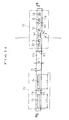
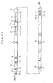
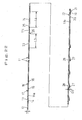
- Figs. 1 and 2 show a developed planar state (a material working state) of a clamping device according to a first embodiment of the invention
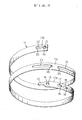
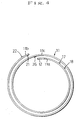
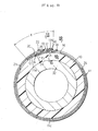
- Figs. 3 through 12 show a roll-bent three-dimensionalized product (a clamping device with a bore diameter of about 35 mm, in the illustrated example) and a usage state thereof.
- stainless steel sheet of SUS 301, 304 316 or 430 (SUS 316, in the illustrated example) or some other metal strip M having a fixed thickness T of about 0.5 - 1.0 mm (0.5 mm, in the illustrated example) and a fixed width W of about 7 - 10 mm (9 mm, in the illustrated example), such beforehand-prepared long-sized material being cut into lengths having a fixed length L (250 mm, in the illustrated example) suited to the thickness of an intended article to be fixed 10, such as a liquid conveying hose, dustproof bellows, shaft coupling boot or the like.
- the numeral 11 denotes a clamp band made of said metal strip material M cut to a fixed length which is then roll-bent in two loops for three-dimensionalization in the form of a circular ring as seen in front view, contributing, as it were, directly to the tightening action on the article to be fixed 10, it being held in a partial three-layer overlap state by a fixed amount X (about 27 mm, in the illustrated example) such that the other roll-bent end side indirectly externally contacts the one roll-bent end side.
- the clamp band 11 with one roll-bent end side forming an inner overlap portion 11a and the other roll-bent end side forming an outer overlap portion 11b is roll-bent in an overall two-loop circular coiled state for three-dimensionalization such that it overlaps in three layers by the fixed amount X in an intermediate position.
- the character 11c denotes an intermediate overlap portion interposed between said inner and outer overlap portions 11a and 11b in said three-layer overlap region by the fixed amount X.
- said intermediate overlap portion 11c as shown in Figs. 7 - 9, continues from said three-layer overlap region by the fixed amount X to one roll-bent end side of the clamp band 11, it assumes a two-layer overlap state internally contacting said outer overlap portion 11b and, as it continues from said three-layer overlap region to the other opposite roll-bent end side of the clamp band 11, it assumes a two-layer overlap state externally contacting said inner overlap portion 11a.
- Said clamp band 11 has, of course, the fixed width W of the metal strip material M itself, but one severed end alone of the inner overlap portion 11a is formed as a pilot nose 12 having a small fixed width W1 (3 mm, in the illustrated example) which is less than about a third of the fixed width W of the clamp band 11 by symmetrically notching the opposite side edges of the metal strip material M.
- the extending length L1 of the pilot nose 12 is dimensioned to be about 7-10 mm (7 mm, in the illustrated example).
- the numeral 13 denotes a roll-bending formation engaging pin receiving hole formed in the internal overlap portion 11a of the clamp band 11 and disposed in the vicinity of the extending proximal end of said pilot nose 12, said hole 13 being adapted to receive an engaging pin extending upright from the circumferential surface of a clamp band roll-bending formation mandrel roll in a forming machine (not shown), said hole 13 being used in a state of engagement with the engaging pin to roll-bend said clamp band 11 in a circular coiled state for three-dimensionalization in that said mandrel roll is driven for rotation.
- said engaging pin receiving hole 13 may be formed circular or elliptic as seen in plan view, and it is preferable that the arrangement be such that particularly with the opening edge thereof on the side adjacent the pilot nose 12 used as a prop-up key stopping edge 14 of straight line segment orthogonal to the longitudinal centerline of the clamp band 11, the engaging pin receiving hole 13, as shown in Figs 1 - 3, is punched out in elongated semicircular or quadrangular form as seen in plan view, thereby stably stopping a prop-up key of the intermediate overlap portion 11c, as will be later described.
- a second fixing tooth receiving hole 15 and a first tool receiving hole 16 are distributively formed in side-by-side relation.
- the second fixing tooth receiving hole 15 and the first tool receiving hole 16 are each elliptic as seen in plan view, lying on the longitudinal centerline of the clamp band 11, whereas the opening edge of said second fixing tooth receiving hole 15 on the side adjacent said engaging pin receiving hole 13 is bent out in an outwardly raised state by a fixed amount of height H1 (about 1 mm, in the illustrated example) corresponding to about 1.5 - 2.0 times the fixed thickness T of the metal strip material M to form a first fixing tooth 17 of raised channel shape in cross section, as shown in Figs. 8, 9 and 11.
- the opening edge of said first tooth receiving hole 16 on the side adjacent said second fixing tooth receiving hole 15 is bent out as a first tool engaging tooth 18 in an outwardly raised state by a fixed amount of height H2 (about 1.2 mm, in the illustrated example) corresponding to about 1.5 - 2.5 times the fixed thickness T of the metal strip material M to form a first tool engaging tooth 18 of raised channel shape in cross section, as shown in 8 - 10, so as to function as a reinforcing bead capable of counteracting a drawing force (a clamp band bore diameter contracting force) exerted by a draw type operating tool F to be later described.
- H2 about 1.2 mm, in the illustrated example
- the outer overlap portion 11b of the clamp band 11 which is to come in external contact with said inner overlap portion 11a in a three-layer overlap state is formed with a first fixing tooth receiving hole 19 and a second tool receiving hole 20 also in side-by-side relation, successively spaced away from the other severed end side.
- Such first fixing tooth receiving hole 19 and second tool receiving hole 20 are elliptic as seen in plan view.
- the opening edge of the first fixing tooth receiving hole 19 on the other severed end side is bent out in an inwardly recessed state by a fixed amount of depth D1 (about 1 mm, in the illustrated example) corresponding to about 1.5 - 2.0 times the fixed thickness T of the metal strip material M to form a second fixing tooth 21 of recessed channel shape in cross section, as shown in Figs. 8, 9 and 11.
- said first fixing tooth 17 of raised channel shape bent out in an outwardly raised state from the inner overlap portion 11a of the clamp band 11 and the second fixing tooth 21 of recessed channel shape bent out in an inwardly recessed state from the outer overlap portion 11b constitute a mechanical fastening means for the clamp band 11, the arrangement being such that the teeth, which are in opposed male and female relation, seizure-wise engage each other in an overlap state by a fixed amount L2 (about 0.5 mm, in the illustrated example) through a tool relief reception communication hole in the intermediate overlap portion 11c to be later described.
- the opening edge of the second tool receiving hole 20 on the side adjacent said first fixing tooth receiving hole 19 is bent out also in an outwardly raised state by a fixed amount of height H3 (about 1 mm, in the illustrated example) corresponding to about 1.5 - 2.0 times the fixed thickness T of the metal strip material M to form a second tool engaging tooth 22 of raised channel shape standing side by side with the first tool engaging tooth 18 of said inner overlap portion 11a, as shown in Figs. 8 and 9, said second tool engaging tooth22 functioning as a reinforcing bead for the same purpose as that of said first tool engaging tooth 18.
- the numeral 23 denotes a nose receiving hole which is formed elongated in the intermediate overlap portion 11c existing in the region where the inner and outer overlap portions 11a and 11b overlap in three layers by a fixed amount X, in such a manner as to assume an elliptic shape as seen in plan view, lying on the longitudinal centerline of the clamp band 11, said hole 23 relief-wise receiving the pilot nose 12 of said inner overlap portion 11a, thereby maintaining the inner peripheral surface (tightening surface) of the clamp band 11 in a flush smooth state.
- the character L3 denotes the opening length (which is 20 mm, in the illustrated example) of the nose receiving hole 23, said opening length being dimensioned to be much greater than the extending length L1 of said pilot nose 12.
- the intermediate overlap portion 11c disposed nearer to the side where the outer overlap portion 11b exists as seen from said nose receiving hole 23 is formed with a tool relief reception communication hole 24 which is in side-by-side relation to the nose receiving hole 23 and which is of elongated elliptic shape as seen in plan view, said communication hole 24 communicating with the second fixing tooth receiving hole 15 and first tool receiving hole 16 in said inner overlap portion 11a, thereby relief-wise receiving said first fixing tooth 17 and first tool engaging tooth 18 in the communication hole 24.
- the character L4 denotes the opening length of the tool relief reception communication hole 24, said opening length being dimensioned to be 30 mm in the illustrated example.
- said engaging pin receiving hole 13, said first and second fixing tooth receiving holes 19 and 15, said first and second tool receiving holes 16 and 20, said nose receiving hole 23 and said tool relief reception communication hole 24 all have substantially the same opening width W2 (4 mm, in the illustrated example) , which is dimensioned to have a little more than a third of the fixed width W of the clamp band 11.
- the working teeth of the draw type operating tool F to be later described can be reliably and stably inserted and engaged between the first tool engaging tooth 18 and the second tool engaging tooth 22, standing upright in side-by-side relation, of raised channel shape bent out also in an outwardly raised state from the outer overlap portion 11b of the clamp band 11.
- the pilot nose 12 of the inner overlap portion 11a internally contacting the intermediate overlap portion 11c of said clamp band 11 comes to be relief-wise received in the nose receiving hole 23 in the intermediate overlap portion 11c, and besides this, said first fixing tooth 17 and first tool engaging tooth 18 bent out in an outwardly raised state from the inner overlap portion 11a come to be relief-wise received in the tool relief reception communication hole 24 in said intermediate overlap portion 11c, with the result that even if the clamping device is a two-loop coiled type clamping device, it can be wholly greatly flattened and the inner peripheral surface (tightening surface) of the clamp band 11 can be maintained in a high degree of circularity ring state and in a flush smooth state.
- the nose receiving hole 23 and the tool relief reception communicated hole 24 in the intermediate overlap portion 11c are formed to be of elongated elliptic shape as seen in plan view. It is preferable that the opening edge of said tool relief reception communication hole 24 on the side adjacent the nose receiving hole 23, like the prop-up key stopping edge 14 of said engaging pin receiving hole 13, be punched out particularly as a second fixing tooth temporarily fixing edge 25 of straight line segment orthogonal to the longitudinal centerline of the clamp band 11.
- the opening edge of said nose receiving hole 23 on the side adjacent the tool relief reception communication hole 24 is bent out in an obliquely inwardly recessed state by a fixed amount of depth D2 (0.5 mm, in the illustrated example) substantially corresponding to the fixed thickness T of the metal strip material M to serve as a prop-up key 26 which is in such a positional relation as to be capable of seizure-wise engage the prop-up key stopping edge 14 of the engaging pin receiving hole 13 formed in the inner overlap portion 11a; thus, it is desirable that the arrangement be such that when the first and second fixing teeth 17 and 21 of the inner and outer overlap portions 11a and 11b, respectively, seizure-wise engage each other and the clamp band 11 is fasteningly fixed at the final bore diameter, the prop-up key 26 of said intermediate overlap portion 11c is stopped by the prop-up key stopping edge 14 of the inner overlap portion 11a.
- D2 0.5 mm, in the illustrated example
- the prop-up restrain action of the prop-up key 26 enables the seizure engagement state of said first and second fixing teeth 17 and 21 to be locked against accidental unlocking, further improving reliability and draw operation safety as a claming device.
- Such the two-loop coiled type claming device of the invention can be mass-produced from said stainless steel sheet or metal strip material M, as follows.
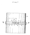
- a punching-out process is performed by using a first press punching-out die P1 to form the pilot nose 12, engaging pin receiving hole 13, first and second tooth receiving holes 15 and 19, and first and second tool receiving holes 16 and 20 in the clamp band 11, and by using a second press punching-out die P2 to form the nose receiving hole 23 and tool relief reception communication hole 24 in the clamp band 11.
- the punching-out process state using the two types of first and second press punching-out dies P1 and P2 is as shown in Figs. 13 - 15.
- the metal strip material M is passed through a press bent-up die (not shown) to effect the bending-up of the first and second fixing teeth 17 and 21, first and second tool engaging teeth 18 and 22, and prop-up key 26 in the clamp band 11.
- the bending-up process state is as shown in Figs. 16 and 17. In that case, whereas the first fixing tooth 17 and the first and second tool engaging teeth 18 and 22 are bent up outwardly in a raised channel shape, the second fixing tooth 21 of recessed channel shape and the prop-up key 26 are bent up reversely or inwardly.
- said long-sized metal strip material M is severed at a position shown by the character C-C in Figs. 13 - 17, whereby it is dimensioned to be a fixed length L necessary for the clamp band 11.
- the clamp band 11 of fixed length L in a still developed planar state is fed from said transfer line into an unillustrated forming machine, which causes said inner and outer overlap portions 11a and 11b to overlap each other by the fixed amount X in three layers through the intermediate overlap portion 11c, roll-bent for three-dimensionalization in an overall two-loop circular coiled state, completing a product as shown in Figs. 3 - 5.
- the first fixing tooth 17 of the invention is bent out in an outwardly raised state from the vicinity of one severed end of the inner overlap portion 11a of the clamp band 11; therefore, in multiproduct production of clamping devices in which the bore diameter of the clamp band 11 varies, the distance Y between said first and second fixing teeth 17 and 21 can be adjusted very easily as if the clamping device were a one-loop clamping device, without causing any trouble in calculation. Because of elimination of the need to change said press die each time, the invention is extremely superior in coping with , variations in the thickness of the article to be fixed 10 and in mass producibility of clamping devices.
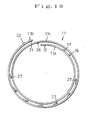
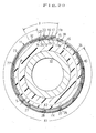
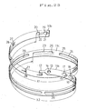
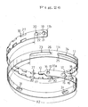
- Figs. 18 - 30 show second - fifth embodiments of the invention.
- a plurality of float leg pieces 27 dottedly distributed throughout the external contact region X1 as shown in Figs. 18 - 22 may be cut up in an obliquely inwardly bent state, by a fixed amount of depth D3 (about 1 mm, in the illustrated example) corresponding to about 1 - 2 times the fixed thickness T of the metal strip material M.
- an expansion/contraction spring force directed diametrically of the clamp band 11 is stored by floating the external contact region X1 having a plurality of float leg pieces 27 cut up and distributed therein from the internal contact region X2 so as to keep a fixed clearance S with respect to the internal contact region X2 extending from the nose receiving hole 23 in said intermediate overlap portion 11c internally contacted therewith in a two-layer overlap state to the first tool receiving hole 16 in the inner overlap portion 11a.
- the clamp band 11 can be always closely contacted with the article to be fixed 10 over the entire surface, by the action of the clamp band 11 of absorbing changes in the rigidity and thickness of the article to be fixed 10 with said float leg pieces 27 serving as the expansion/contraction spring elements of the clamp band 11 itself.
- cutting lines 28 substantially U-shaped as seen in plan view, are applied to the longitudinal centerline of the metal strip material M in a dottedly distributed state with a fixed spacing pitch and the float leg pieces 27 are bent up obliquely inwardly from the cutting lines 28 as in said prop-up key 26, with the bent-up front ends thereof being elastically contacted with the internal contact region X2 which is in two-layer overlap relation to said external contact region X1.
- the plurality of float leg pieces 27 interposed between the external and internal contact regions X1 and X2 can, as expansion/contraction spring elements of the clamp band 11 itself, spontaneously elastically absorb or adjust changes in the thickness or hardness of the article to be fixed 10 to allow the clamp band 11 to exert a tightening force to closely contact the article to be fixed 10 throughout the surface, then as in the case of the third embodiment of Figs. 23 - 25, the plurality of float leg pieces 27 are cut up obliquely inwardly from the external contact region X1, as in the case of the second embodiment of Figs.
- one or more of the extremely elongated leg piece receiving holes 29 for relief-wise receiving two or more of the float leg pieces 27 may be formed in the internal contact region X2 which is in two-layer overlap relation to said external contact region X1, also along the longitudinal centerline of the metal strip material M.
- the plurality of float leg pieces 27 are adapted to be relief-wise received in the leg piece receiving hole 29, there is no danger that the internal and external contact regions X2 and X1 in a two-layer overlap state are caused to undergo positional deviation free movement relatively transversely (axially of the article to be fixed) during draw operation of the clamp band 11 by an operating tool F to be later described, and there is another advantage that the clamp band 11 for the two-loop coiled type clamping device can rationally be made light in weight by punching out said leg piece receiving hole 29.
- float leg pieces 27 are obliquely inwardly bent up from each pair of cutting lines 30, while one or more transverse shift preventing pieces 31 positioned on the longitudinal centerline of the metal strip material M can be cut up in an outwardly bent state from said internal contact region X2 of the clamp band 11, so as to be interposed between said float leg pieces 27 dottedly distributed on opposite side edges.
- the plurality of float leg pieces 27 are cut up in an obliquely inwardly bent state from the two-layer overlapping external contact region X1 of the clamp band 11; however, as shown in the fifth embodiment of Fig. 29 and 30, said float leg pieces 27 may be cut up reversely or obliquely outwardly from the internal contact region X2 of the clamp band 11, the cut-up front end thereof being elastically contacted with said external contact region X1.
- the float leg pieces 27 are disposed in pairs in symmetrical side-by-side relation, in the opposed side edges of the metal strip material M; however, they may be bent up obliquely inwardly or outwardly in alternating staggered relation with a fixed spacing pitch from opposite side edges of the metal strip material M.
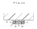
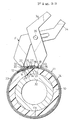
- the clamping device which is of the two-loop coiled type, of the invention is a product which is two-loop roll-bent for three-dimensionalization as a whole with the inner and outer overlap portions 11a and 11b of the clamp band 11 held in a three-layer overlap state at an intermediate position by a fixed amount X; therefore, in fasteningly fixing a fluid conveying hose, dustproof bellows, shaft coupling boot or some other article to be fixed 10 to the connecting circumferential surface 32 of optional equipment A associated therewith, said clamp band 11 is fit-set on the article to be fixed 10 as shown in Fig. 31.
- the clamp band 11 is of open type having both ends severed, it is not impossible to wrappingly set so as to diametrically (transversely) insert it on the article to be fixed 10.
- the inner and outer overlap portions 11a and 11b of the clamp band 11 overlap each other in a slacked state, with the second fixing tooth receiving hole 15 and first tool receiving hole 16 in the inner overlap portion 11a being in communication with the tool relief reception communication hole 24 in the intermediate overlap portion 11c externally contacted therewith.
- the first tool engaging tooth 18 of raised channel shape bent out in an outwardly raised state from the opening edge of the first tool receiving hole 16 and the second tool engaging tooth 22 of raised channel shape bent out also in an outwardly raised state from the opening edge of the second tool receiving hole 20 in the outer overlap portion 11b of the clamp band 11 are held mutually reversely directed, with the first and second tool engaging teeth 18 and 22 standing side-by-side relation through the tool relief reception communication hole 24.
- a pair of working teeth 33 installed on the front ends of a draw operating tool F as shown in Fig. 3I are inserted from outside into the first and second tool engaging teeth 18 and 22 of the clamp band 11 and engaged with the latter, and then the operator strongly grips the pair of handles 34 of the operating tool F to draw said pair of working teeth 33 toward each other around the axis of an assemble pivot shaft 35.
- the bore diameter of the clamp band 11 is forcibly contractively deformed from its slacked state at the initial stage of preparation as in Fig. 31 and the pilot nose 12 forming one severed end of the inner overlap portion 11a runs into the nose receiving hole 23 in the intermediate overlap portion 11c externally contacting the same, while the first fixing tooth 17 of raised channel shape bent out in an outwardly raised state from the inner overlap portion 11a and the second fixing tooth 21 of recessed channel shape bent out in a reverse or inwardly recessed state from the outer overlap portion 11b move across each other as in Fig.
- the first and second fixing teeth 17 and 21 come in seizure engagement with each other within the tool relief reception communication hole 24 formed in the intermediate overlap portion 11c and in a plane substantially bisecting the fixed thickness of the intermediate overlap portion 11c, so that the inner and outer overlap portions 11a and 11b can be drawn to the intermediate overlap portion 11c and closely contacted therewith.
- a fasteningly fixed state having overall flatness and circularity is obtained.
- the first fixing tooth 17 of raised channel shape bent out in an outwardly raised state from said inner overlap portion 11a of the clamp band 11 and the second fixing tooth 21 of recessed channel shape bent out in a reverse or inwardly recessed state from said outer overlap portion 11b seizure-wise engage each other by the fixed amount L2 in the communication hole 24 particularly through the tool relief reception communication hole 24 formed in said intermediate overlap portion 11c; therefore, even if said first and second fixing teeth 17 and 21 spring back after moving across each other, the post-slack in the clamp band 11 can be rationally suppressed to the minimum necessary and a superior tensile strength can also be obtained.
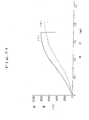
- Fig. 34 shows a load-elongation graph (S-S curve diagram) resulting from comparative tests using as test samples the two-loop coiled type clamping device of the invention made of previously exemplified SUS 316 stainless steel sheet having a thickness T of 0.5 mm, a width W of 9 mm, and a length L of 250 mm, and roll-bent for three-dimensionalization to a bore diameter of about 35 mm, and that of the known inventions (Japanese Patent No. 2898613, described as an original state without having float leg pieces serving as expansion/contraction spring elements) described in the outset, three pieces each, by Tensile Tester "UCT-25T" of Orientic Corporation.
- the graph refers to the mean value of the invention and refers to the mean value of the known inventions.
- the elongation is 2.2 mm at the maximum load point of 6678 N, whereas in the invention, the elongation is 1.75 mm at the maximum load point of 8476 N, showing that the amount of post-slack in the clamp band 11 is remarkably reduced, exerting a high tensile strength.
- the clamping device of the invention there is no restriction imposed on the article to be fixed 10 to which it is applied, and even if the article to be fixed 10 is a dustproof bellows, shaft coupling boot or the like formed of rigid synthetic resin material, which is originally inelastic, with a thin wall of about 1.0 - 1.5 mm, it can be fasteningly fixed to the connecting circumferential surface 32 of optional equipment A in an overall closely contacted state without the danger of slacking.
- the opening edge of the tool relief reception communication hole 24 formed in the intermediate overlap portion 11c is shaped as the second fixing tooth temporarily fixing edge 25, then in an intermediate process before the clamp band 11 reaches the intended final bore diameter, the second fixing tooth 21 of recessed channel shape of the outer overlap portion 11b, as shown in Fig.
- the opening edge of the nose receiving hole 23 formed in said intermediate overlap portion 11c is bent out in an obliquely inwardly recessed state by the fixed amount of depth D2 from the intermediate overlap portion 11c to form a prop-up key 26, while the opening edge of the engaging pin receiving hole 13 formed in the inner overlap portion 11a is shaped as the stopping edge 14 for the prop-up key 26.
Landscapes
- Engineering & Computer Science (AREA)
- General Engineering & Computer Science (AREA)
- Mechanical Engineering (AREA)
- Clamps And Clips (AREA)
- Joints That Cut Off Fluids, And Hose Joints (AREA)
Applications Claiming Priority (2)
| Application Number | Priority Date | Filing Date | Title |
|---|---|---|---|
| JP2003272349 | 2003-07-09 | ||
| JP2003272349A JP3799343B2 (ja) | 2003-07-09 | 2003-07-09 | 2重渦巻き型クランプ金具 |
Publications (1)
| Publication Number | Publication Date |
|---|---|
| EP1496300A1 true EP1496300A1 (fr) | 2005-01-12 |
Family
ID=33448049
Family Applications (1)
| Application Number | Title | Priority Date | Filing Date |
|---|---|---|---|
| EP04013110A Withdrawn EP1496300A1 (fr) | 2003-07-09 | 2004-06-03 | Collier de serrage à deux tours |
Country Status (6)
| Country | Link |
|---|---|
| US (1) | US7013534B2 (fr) |
| EP (1) | EP1496300A1 (fr) |
| JP (1) | JP3799343B2 (fr) |
| KR (1) | KR100578255B1 (fr) |
| CN (1) | CN1576676A (fr) |
| DE (1) | DE04013110T1 (fr) |
Cited By (2)
| Publication number | Priority date | Publication date | Assignee | Title |
|---|---|---|---|---|
| KR100578255B1 (ko) | 2003-07-09 | 2006-05-11 | 가부시키가이샤 겐록 | 2중 와류형 클램프 쇠장식 |
| EP3228877A4 (fr) * | 2014-12-05 | 2018-07-11 | Suncall Corporation | Bande de serrage |
Families Citing this family (15)
| Publication number | Priority date | Publication date | Assignee | Title |
|---|---|---|---|---|
| GB0612978D0 (en) * | 2006-06-30 | 2006-08-09 | Technip France | Method and apparatus for mounting distributed buoyancy modules on a rigid pipeline |
| JP5167012B2 (ja) | 2008-07-28 | 2013-03-21 | 矢崎総業株式会社 | 電線固定部材 |
| JP4744640B1 (ja) * | 2010-10-15 | 2011-08-10 | 株式会社ミハマ | 締付けバンド |
| KR101269686B1 (ko) * | 2010-11-22 | 2013-05-30 | (주)동아금속 | 호스용 클램프 |
| US8635745B2 (en) * | 2010-11-23 | 2014-01-28 | Panduit Corp. | Metal locking tie |
| US9004414B2 (en) * | 2011-02-08 | 2015-04-14 | David P. Durben | Flexible securing device |
| JP5970264B2 (ja) * | 2012-07-02 | 2016-08-17 | イビデン株式会社 | 巻付体、及び、排ガス浄化装置 |
| JP5877764B2 (ja) * | 2012-07-10 | 2016-03-08 | 日本発條株式会社 | ブーツバンド |
| DE102013003315B3 (de) * | 2013-02-28 | 2014-06-18 | Olympus Winter & Ibe Gmbh | Endoskop |
| WO2015011789A1 (fr) * | 2013-07-23 | 2015-01-29 | 日本発條株式会社 | Collier de serrage |
| CN105889626A (zh) * | 2016-05-25 | 2016-08-24 | 重庆芦霖建材厂 | 排水管道连接器 |
| WO2018082763A1 (fr) * | 2016-11-02 | 2018-05-11 | Oetiker Schweiz Ag | Collier de serrage |
| US10224668B2 (en) | 2017-10-20 | 2019-03-05 | Isodyne, Inc. | Assembly for terminating an EMF shielded cable harness at an electrical component port |
| US11940073B2 (en) * | 2019-02-22 | 2024-03-26 | Oetiker Schweiz Ag | Hose clamp |
| US12252290B2 (en) * | 2019-11-12 | 2025-03-18 | Genbe Co., Ltd | Collecting tool |
Citations (3)
| Publication number | Priority date | Publication date | Assignee | Title |
|---|---|---|---|---|
| US3833969A (en) * | 1973-08-29 | 1974-09-10 | Deco Prod Co | Circular hose clamp |
| US4998326A (en) * | 1989-12-06 | 1991-03-12 | Hans Oetiker Ag Maschioen- Und Apparatefabrik | Balanced clamp structure |
| EP0828107A2 (fr) * | 1996-09-05 | 1998-03-11 | Kabushiki Kaisha Kenlock | Collier de serrage à deux tours |
Family Cites Families (9)
| Publication number | Priority date | Publication date | Assignee | Title |
|---|---|---|---|---|
| US4492004A (en) * | 1982-12-03 | 1985-01-08 | Hans Oetiker | Earless clamp structure |
| US5138746A (en) * | 1990-04-06 | 1992-08-18 | Nkh Spring Co., Ltd. | Clamp structure |
| US5283931A (en) * | 1992-05-20 | 1994-02-08 | Hans Oetiker Ag Maschinen- Und Apparatefabrik | Reusable earless clamp structure |
| JPH0754710Y2 (ja) * | 1993-03-31 | 1995-12-18 | 株式会社ケンロック | クランプ金具 |
| KR970000888Y1 (ko) * | 1993-04-23 | 1997-02-12 | 가부시끼가이샤 오오사까 산꼬오 세이사꾸쇼 | 클램프 금구 |
| JPH0750631A (ja) | 1993-08-05 | 1995-02-21 | Toshiba Corp | 擬似背景雑音発生機能を備えたディジタル無線通信装置 |
| JP2652136B2 (ja) * | 1994-07-21 | 1997-09-10 | 株式会社ケンロック | クランプ金具 |
| US5615456A (en) | 1994-08-19 | 1997-04-01 | Hans Oetiker Ag Maschinen- Und Apparate-Fabrik | Tolerance-compensating reusable clamp structure |
| JP3799343B2 (ja) | 2003-07-09 | 2006-07-19 | 株式会社ケンロック | 2重渦巻き型クランプ金具 |
-
2003
- 2003-07-09 JP JP2003272349A patent/JP3799343B2/ja not_active Expired - Fee Related
-
2004
- 2004-06-03 DE DE04013110T patent/DE04013110T1/de active Pending
- 2004-06-03 EP EP04013110A patent/EP1496300A1/fr not_active Withdrawn
- 2004-06-08 US US10/863,728 patent/US7013534B2/en not_active Expired - Fee Related
- 2004-07-05 CN CNA2004100688060A patent/CN1576676A/zh active Pending
- 2004-07-08 KR KR1020040052919A patent/KR100578255B1/ko not_active Expired - Fee Related
Patent Citations (3)
| Publication number | Priority date | Publication date | Assignee | Title |
|---|---|---|---|---|
| US3833969A (en) * | 1973-08-29 | 1974-09-10 | Deco Prod Co | Circular hose clamp |
| US4998326A (en) * | 1989-12-06 | 1991-03-12 | Hans Oetiker Ag Maschioen- Und Apparatefabrik | Balanced clamp structure |
| EP0828107A2 (fr) * | 1996-09-05 | 1998-03-11 | Kabushiki Kaisha Kenlock | Collier de serrage à deux tours |
Cited By (2)
| Publication number | Priority date | Publication date | Assignee | Title |
|---|---|---|---|---|
| KR100578255B1 (ko) | 2003-07-09 | 2006-05-11 | 가부시키가이샤 겐록 | 2중 와류형 클램프 쇠장식 |
| EP3228877A4 (fr) * | 2014-12-05 | 2018-07-11 | Suncall Corporation | Bande de serrage |
Also Published As
| Publication number | Publication date |
|---|---|
| JP3799343B2 (ja) | 2006-07-19 |
| JP2005030528A (ja) | 2005-02-03 |
| DE04013110T1 (de) | 2005-05-04 |
| KR20050007156A (ko) | 2005-01-17 |
| KR100578255B1 (ko) | 2006-05-11 |
| US7013534B2 (en) | 2006-03-21 |
| CN1576676A (zh) | 2005-02-09 |
| US20050005405A1 (en) | 2005-01-13 |
Similar Documents
| Publication | Publication Date | Title |
|---|---|---|
| US7013534B2 (en) | Two-loop coiled type clamping device | |
| EP0828107B1 (fr) | Collier de serrage à deux tours | |
| US5581851A (en) | Draw operating type clamping device | |
| EP0621431B1 (fr) | Dispositif de serrage | |
| CN100374357C (zh) | 具有可塑性变形的耳状物的敞开型软管夹紧件及其制造方法 | |
| CA2485625C (fr) | Collier de serrage ouvert a oreille deformable et son procede de fabrication | |
| US5375299A (en) | Clamping device | |
| US11940073B2 (en) | Hose clamp | |
| US6023815A (en) | Hose clip | |
| HK1068678A (en) | Two-loop coiled type clamping device | |
| US20060117534A1 (en) | Open hose clamp with plastically deformable ear | |
| JP2947466B2 (ja) | 2重渦巻き型クランプ金具 | |
| JP3422318B2 (ja) | 開放型クランプ金具 | |
| JPH0747672Y2 (ja) | クランプ金具 | |
| JP4476637B2 (ja) | クランプバンド | |
| JP2898613B2 (ja) | 2重渦巻き型クランプ金具 | |
| JPH0747671Y2 (ja) | クランプ金具 | |
| JPH07793Y2 (ja) | 締付バンド |
Legal Events
| Date | Code | Title | Description |
|---|---|---|---|
| PUAI | Public reference made under article 153(3) epc to a published international application that has entered the european phase |
Free format text: ORIGINAL CODE: 0009012 |
|
| 17P | Request for examination filed |
Effective date: 20040603 |
|
| AK | Designated contracting states |
Kind code of ref document: A1 Designated state(s): AT BE BG CH CY CZ DE DK EE ES FI FR GB GR HU IE IT LI LU MC NL PL PT RO SE SI SK TR |
|
| AX | Request for extension of the european patent |
Extension state: AL HR LT LV MK |
|
| REG | Reference to a national code |
Ref country code: SE Ref legal event code: TRCL |
|
| EL | Fr: translation of claims filed | ||
| REG | Reference to a national code |
Ref country code: HK Ref legal event code: DE Ref document number: 1068678 Country of ref document: HK |
|
| DET | De: translation of patent claims | ||
| AKX | Designation fees paid |
Designated state(s): DE FR GB IT SE |
|
| GRAP | Despatch of communication of intention to grant a patent |
Free format text: ORIGINAL CODE: EPIDOSNIGR1 |
|
| STAA | Information on the status of an ep patent application or granted ep patent |
Free format text: STATUS: THE APPLICATION IS DEEMED TO BE WITHDRAWN |
|
| 18D | Application deemed to be withdrawn |
Effective date: 20080722 |
|
| REG | Reference to a national code |
Ref country code: HK Ref legal event code: WD Ref document number: 1068678 Country of ref document: HK |