EP1496322B1 - Refrigerateur - Google Patents
Refrigerateur Download PDFInfo
- Publication number
- EP1496322B1 EP1496322B1 EP03715460.6A EP03715460A EP1496322B1 EP 1496322 B1 EP1496322 B1 EP 1496322B1 EP 03715460 A EP03715460 A EP 03715460A EP 1496322 B1 EP1496322 B1 EP 1496322B1
- Authority
- EP
- European Patent Office
- Prior art keywords
- temperature
- compressor
- refrigerant
- fan
- evaporator
- Prior art date
- Legal status (The legal status is an assumption and is not a legal conclusion. Google has not performed a legal analysis and makes no representation as to the accuracy of the status listed.)
- Expired - Lifetime
Links
Images


Classifications
-
- F—MECHANICAL ENGINEERING; LIGHTING; HEATING; WEAPONS; BLASTING
- F25—REFRIGERATION OR COOLING; COMBINED HEATING AND REFRIGERATION SYSTEMS; HEAT PUMP SYSTEMS; MANUFACTURE OR STORAGE OF ICE; LIQUEFACTION SOLIDIFICATION OF GASES
- F25D—REFRIGERATORS; COLD ROOMS; ICE-BOXES; COOLING OR FREEZING APPARATUS NOT OTHERWISE PROVIDED FOR
- F25D11/00—Self-contained movable devices, e.g. domestic refrigerators
-
- F—MECHANICAL ENGINEERING; LIGHTING; HEATING; WEAPONS; BLASTING
- F25—REFRIGERATION OR COOLING; COMBINED HEATING AND REFRIGERATION SYSTEMS; HEAT PUMP SYSTEMS; MANUFACTURE OR STORAGE OF ICE; LIQUEFACTION SOLIDIFICATION OF GASES
- F25D—REFRIGERATORS; COLD ROOMS; ICE-BOXES; COOLING OR FREEZING APPARATUS NOT OTHERWISE PROVIDED FOR
- F25D29/00—Arrangement or mounting of control or safety devices
-
- F—MECHANICAL ENGINEERING; LIGHTING; HEATING; WEAPONS; BLASTING
- F25—REFRIGERATION OR COOLING; COMBINED HEATING AND REFRIGERATION SYSTEMS; HEAT PUMP SYSTEMS; MANUFACTURE OR STORAGE OF ICE; LIQUEFACTION SOLIDIFICATION OF GASES
- F25B—REFRIGERATION MACHINES, PLANTS OR SYSTEMS; COMBINED HEATING AND REFRIGERATION SYSTEMS; HEAT PUMP SYSTEMS
- F25B1/00—Compression machines, plants or systems with non-reversible cycle
-
- F—MECHANICAL ENGINEERING; LIGHTING; HEATING; WEAPONS; BLASTING
- F25—REFRIGERATION OR COOLING; COMBINED HEATING AND REFRIGERATION SYSTEMS; HEAT PUMP SYSTEMS; MANUFACTURE OR STORAGE OF ICE; LIQUEFACTION SOLIDIFICATION OF GASES
- F25B—REFRIGERATION MACHINES, PLANTS OR SYSTEMS; COMBINED HEATING AND REFRIGERATION SYSTEMS; HEAT PUMP SYSTEMS
- F25B5/00—Compression machines, plants or systems, with several evaporator circuits, e.g. for varying refrigerating capacity
- F25B5/02—Compression machines, plants or systems, with several evaporator circuits, e.g. for varying refrigerating capacity arranged in parallel
-
- F—MECHANICAL ENGINEERING; LIGHTING; HEATING; WEAPONS; BLASTING
- F25—REFRIGERATION OR COOLING; COMBINED HEATING AND REFRIGERATION SYSTEMS; HEAT PUMP SYSTEMS; MANUFACTURE OR STORAGE OF ICE; LIQUEFACTION SOLIDIFICATION OF GASES
- F25B—REFRIGERATION MACHINES, PLANTS OR SYSTEMS; COMBINED HEATING AND REFRIGERATION SYSTEMS; HEAT PUMP SYSTEMS
- F25B9/00—Compression machines, plants or systems, in which the refrigerant is air or other gas of low boiling point
- F25B9/002—Compression machines, plants or systems, in which the refrigerant is air or other gas of low boiling point characterised by the refrigerant
-
- F—MECHANICAL ENGINEERING; LIGHTING; HEATING; WEAPONS; BLASTING
- F25—REFRIGERATION OR COOLING; COMBINED HEATING AND REFRIGERATION SYSTEMS; HEAT PUMP SYSTEMS; MANUFACTURE OR STORAGE OF ICE; LIQUEFACTION SOLIDIFICATION OF GASES
- F25D—REFRIGERATORS; COLD ROOMS; ICE-BOXES; COOLING OR FREEZING APPARATUS NOT OTHERWISE PROVIDED FOR
- F25D17/00—Arrangements for circulating cooling fluids; Arrangements for circulating gas, e.g. air, within refrigerated spaces
- F25D17/04—Arrangements for circulating cooling fluids; Arrangements for circulating gas, e.g. air, within refrigerated spaces for circulating air, e.g. by convection
- F25D17/06—Arrangements for circulating cooling fluids; Arrangements for circulating gas, e.g. air, within refrigerated spaces for circulating air, e.g. by convection by forced circulation
- F25D17/062—Arrangements for circulating cooling fluids; Arrangements for circulating gas, e.g. air, within refrigerated spaces for circulating air, e.g. by convection by forced circulation in household refrigerators
- F25D17/065—Arrangements for circulating cooling fluids; Arrangements for circulating gas, e.g. air, within refrigerated spaces for circulating air, e.g. by convection by forced circulation in household refrigerators with compartments at different temperatures
-
- F—MECHANICAL ENGINEERING; LIGHTING; HEATING; WEAPONS; BLASTING
- F25—REFRIGERATION OR COOLING; COMBINED HEATING AND REFRIGERATION SYSTEMS; HEAT PUMP SYSTEMS; MANUFACTURE OR STORAGE OF ICE; LIQUEFACTION SOLIDIFICATION OF GASES
- F25B—REFRIGERATION MACHINES, PLANTS OR SYSTEMS; COMBINED HEATING AND REFRIGERATION SYSTEMS; HEAT PUMP SYSTEMS
- F25B2400/00—Component parts or details not otherwise provided for in this subclass
- F25B2400/04—Refrigeration circuit bypassing means
-
- F—MECHANICAL ENGINEERING; LIGHTING; HEATING; WEAPONS; BLASTING
- F25—REFRIGERATION OR COOLING; COMBINED HEATING AND REFRIGERATION SYSTEMS; HEAT PUMP SYSTEMS; MANUFACTURE OR STORAGE OF ICE; LIQUEFACTION SOLIDIFICATION OF GASES
- F25B—REFRIGERATION MACHINES, PLANTS OR SYSTEMS; COMBINED HEATING AND REFRIGERATION SYSTEMS; HEAT PUMP SYSTEMS
- F25B2400/00—Component parts or details not otherwise provided for in this subclass
- F25B2400/04—Refrigeration circuit bypassing means
- F25B2400/0409—Refrigeration circuit bypassing means for evaporators
-
- F—MECHANICAL ENGINEERING; LIGHTING; HEATING; WEAPONS; BLASTING
- F25—REFRIGERATION OR COOLING; COMBINED HEATING AND REFRIGERATION SYSTEMS; HEAT PUMP SYSTEMS; MANUFACTURE OR STORAGE OF ICE; LIQUEFACTION SOLIDIFICATION OF GASES
- F25B—REFRIGERATION MACHINES, PLANTS OR SYSTEMS; COMBINED HEATING AND REFRIGERATION SYSTEMS; HEAT PUMP SYSTEMS
- F25B2400/00—Component parts or details not otherwise provided for in this subclass
- F25B2400/04—Refrigeration circuit bypassing means
- F25B2400/0411—Refrigeration circuit bypassing means for expansion valves or capillary tubes
-
- F—MECHANICAL ENGINEERING; LIGHTING; HEATING; WEAPONS; BLASTING
- F25—REFRIGERATION OR COOLING; COMBINED HEATING AND REFRIGERATION SYSTEMS; HEAT PUMP SYSTEMS; MANUFACTURE OR STORAGE OF ICE; LIQUEFACTION SOLIDIFICATION OF GASES
- F25B—REFRIGERATION MACHINES, PLANTS OR SYSTEMS; COMBINED HEATING AND REFRIGERATION SYSTEMS; HEAT PUMP SYSTEMS
- F25B2400/00—Component parts or details not otherwise provided for in this subclass
- F25B2400/12—Inflammable refrigerants
-
- F—MECHANICAL ENGINEERING; LIGHTING; HEATING; WEAPONS; BLASTING
- F25—REFRIGERATION OR COOLING; COMBINED HEATING AND REFRIGERATION SYSTEMS; HEAT PUMP SYSTEMS; MANUFACTURE OR STORAGE OF ICE; LIQUEFACTION SOLIDIFICATION OF GASES
- F25B—REFRIGERATION MACHINES, PLANTS OR SYSTEMS; COMBINED HEATING AND REFRIGERATION SYSTEMS; HEAT PUMP SYSTEMS
- F25B2500/00—Problems to be solved
- F25B2500/26—Problems to be solved characterised by the startup of the refrigeration cycle
-
- F—MECHANICAL ENGINEERING; LIGHTING; HEATING; WEAPONS; BLASTING
- F25—REFRIGERATION OR COOLING; COMBINED HEATING AND REFRIGERATION SYSTEMS; HEAT PUMP SYSTEMS; MANUFACTURE OR STORAGE OF ICE; LIQUEFACTION SOLIDIFICATION OF GASES
- F25B—REFRIGERATION MACHINES, PLANTS OR SYSTEMS; COMBINED HEATING AND REFRIGERATION SYSTEMS; HEAT PUMP SYSTEMS
- F25B2600/00—Control issues
- F25B2600/02—Compressor control
- F25B2600/025—Compressor control by controlling speed
-
- F—MECHANICAL ENGINEERING; LIGHTING; HEATING; WEAPONS; BLASTING
- F25—REFRIGERATION OR COOLING; COMBINED HEATING AND REFRIGERATION SYSTEMS; HEAT PUMP SYSTEMS; MANUFACTURE OR STORAGE OF ICE; LIQUEFACTION SOLIDIFICATION OF GASES
- F25B—REFRIGERATION MACHINES, PLANTS OR SYSTEMS; COMBINED HEATING AND REFRIGERATION SYSTEMS; HEAT PUMP SYSTEMS
- F25B2600/00—Control issues
- F25B2600/11—Fan speed control
- F25B2600/111—Fan speed control of condenser fans
-
- F—MECHANICAL ENGINEERING; LIGHTING; HEATING; WEAPONS; BLASTING
- F25—REFRIGERATION OR COOLING; COMBINED HEATING AND REFRIGERATION SYSTEMS; HEAT PUMP SYSTEMS; MANUFACTURE OR STORAGE OF ICE; LIQUEFACTION SOLIDIFICATION OF GASES
- F25B—REFRIGERATION MACHINES, PLANTS OR SYSTEMS; COMBINED HEATING AND REFRIGERATION SYSTEMS; HEAT PUMP SYSTEMS
- F25B2600/00—Control issues
- F25B2600/25—Control of valves
- F25B2600/2511—Evaporator distribution valves
-
- F—MECHANICAL ENGINEERING; LIGHTING; HEATING; WEAPONS; BLASTING
- F25—REFRIGERATION OR COOLING; COMBINED HEATING AND REFRIGERATION SYSTEMS; HEAT PUMP SYSTEMS; MANUFACTURE OR STORAGE OF ICE; LIQUEFACTION SOLIDIFICATION OF GASES
- F25B—REFRIGERATION MACHINES, PLANTS OR SYSTEMS; COMBINED HEATING AND REFRIGERATION SYSTEMS; HEAT PUMP SYSTEMS
- F25B2700/00—Sensing or detecting of parameters; Sensors therefor
- F25B2700/21—Temperatures
- F25B2700/2116—Temperatures of a condenser
- F25B2700/21161—Temperatures of a condenser of the fluid heated by the condenser
-
- F—MECHANICAL ENGINEERING; LIGHTING; HEATING; WEAPONS; BLASTING
- F25—REFRIGERATION OR COOLING; COMBINED HEATING AND REFRIGERATION SYSTEMS; HEAT PUMP SYSTEMS; MANUFACTURE OR STORAGE OF ICE; LIQUEFACTION SOLIDIFICATION OF GASES
- F25B—REFRIGERATION MACHINES, PLANTS OR SYSTEMS; COMBINED HEATING AND REFRIGERATION SYSTEMS; HEAT PUMP SYSTEMS
- F25B2700/00—Sensing or detecting of parameters; Sensors therefor
- F25B2700/21—Temperatures
- F25B2700/2117—Temperatures of an evaporator
- F25B2700/21174—Temperatures of an evaporator of the refrigerant at the inlet of the evaporator
-
- F—MECHANICAL ENGINEERING; LIGHTING; HEATING; WEAPONS; BLASTING
- F25—REFRIGERATION OR COOLING; COMBINED HEATING AND REFRIGERATION SYSTEMS; HEAT PUMP SYSTEMS; MANUFACTURE OR STORAGE OF ICE; LIQUEFACTION SOLIDIFICATION OF GASES
- F25B—REFRIGERATION MACHINES, PLANTS OR SYSTEMS; COMBINED HEATING AND REFRIGERATION SYSTEMS; HEAT PUMP SYSTEMS
- F25B2700/00—Sensing or detecting of parameters; Sensors therefor
- F25B2700/21—Temperatures
- F25B2700/2117—Temperatures of an evaporator
- F25B2700/21175—Temperatures of an evaporator of the refrigerant at the outlet of the evaporator
-
- F—MECHANICAL ENGINEERING; LIGHTING; HEATING; WEAPONS; BLASTING
- F25—REFRIGERATION OR COOLING; COMBINED HEATING AND REFRIGERATION SYSTEMS; HEAT PUMP SYSTEMS; MANUFACTURE OR STORAGE OF ICE; LIQUEFACTION SOLIDIFICATION OF GASES
- F25B—REFRIGERATION MACHINES, PLANTS OR SYSTEMS; COMBINED HEATING AND REFRIGERATION SYSTEMS; HEAT PUMP SYSTEMS
- F25B5/00—Compression machines, plants or systems, with several evaporator circuits, e.g. for varying refrigerating capacity
-
- F—MECHANICAL ENGINEERING; LIGHTING; HEATING; WEAPONS; BLASTING
- F25—REFRIGERATION OR COOLING; COMBINED HEATING AND REFRIGERATION SYSTEMS; HEAT PUMP SYSTEMS; MANUFACTURE OR STORAGE OF ICE; LIQUEFACTION SOLIDIFICATION OF GASES
- F25D—REFRIGERATORS; COLD ROOMS; ICE-BOXES; COOLING OR FREEZING APPARATUS NOT OTHERWISE PROVIDED FOR
- F25D2400/00—General features of, or devices for refrigerators, cold rooms, ice-boxes, or for cooling or freezing apparatus not covered by any other subclass
- F25D2400/04—Refrigerators with a horizontal mullion
-
- F—MECHANICAL ENGINEERING; LIGHTING; HEATING; WEAPONS; BLASTING
- F25—REFRIGERATION OR COOLING; COMBINED HEATING AND REFRIGERATION SYSTEMS; HEAT PUMP SYSTEMS; MANUFACTURE OR STORAGE OF ICE; LIQUEFACTION SOLIDIFICATION OF GASES
- F25D—REFRIGERATORS; COLD ROOMS; ICE-BOXES; COOLING OR FREEZING APPARATUS NOT OTHERWISE PROVIDED FOR
- F25D2700/00—Means for sensing or measuring; Sensors therefor
- F25D2700/12—Sensors measuring the inside temperature
-
- Y—GENERAL TAGGING OF NEW TECHNOLOGICAL DEVELOPMENTS; GENERAL TAGGING OF CROSS-SECTIONAL TECHNOLOGIES SPANNING OVER SEVERAL SECTIONS OF THE IPC; TECHNICAL SUBJECTS COVERED BY FORMER USPC CROSS-REFERENCE ART COLLECTIONS [XRACs] AND DIGESTS
- Y02—TECHNOLOGIES OR APPLICATIONS FOR MITIGATION OR ADAPTATION AGAINST CLIMATE CHANGE
- Y02B—CLIMATE CHANGE MITIGATION TECHNOLOGIES RELATED TO BUILDINGS, e.g. HOUSING, HOUSE APPLIANCES OR RELATED END-USER APPLICATIONS
- Y02B30/00—Energy efficient heating, ventilation or air conditioning [HVAC]
- Y02B30/70—Efficient control or regulation technologies, e.g. for control of refrigerant flow, motor or heating
-
- Y—GENERAL TAGGING OF NEW TECHNOLOGICAL DEVELOPMENTS; GENERAL TAGGING OF CROSS-SECTIONAL TECHNOLOGIES SPANNING OVER SEVERAL SECTIONS OF THE IPC; TECHNICAL SUBJECTS COVERED BY FORMER USPC CROSS-REFERENCE ART COLLECTIONS [XRACs] AND DIGESTS
- Y10—TECHNICAL SUBJECTS COVERED BY FORMER USPC
- Y10S—TECHNICAL SUBJECTS COVERED BY FORMER USPC CROSS-REFERENCE ART COLLECTIONS [XRACs] AND DIGESTS
- Y10S236/00—Automatic temperature and humidity regulation
- Y10S236/09—Fan control
Definitions
- the present invention relates to a refrigerator which has a refrigerating cycle sequentially connecting a compressor, a condenser, a drawing mechanism, and an evaporator and uses a hydrocarbon cooling medium as a refrigerant.
- the HC cooling medium is a combustible cooling medium, so that a risk of ignition is pointed out.
- the necessary amount of the refrigerant charged into the refrigerating cycle may be smaller than a half of that of the HFC cooling medium. Therefore, even if the refrigerant leaks from the refrigerating cycle, there is little possibility of increasing to the ignition concentration, and in a refrigerator provided with the explosion-proof treated electrical parts, the safety thereof is high.
- the HC cooling medium has a characteristic easily soluble into the refrigeration machine oil, for example, a mineral oil compared with the HFC cooling medium and other refrigerants. Therefore a problem arises that the amount of the refrigerant circulating in the refrigerating cycle decreases. In particular, after turning on power when much refrigerant is dissolved in the refrigeration machine oil, there is the possibility of the reduction of the cooling performance.
- the charged amount of HC cooling medium is small, the effect due to the dissolving into the refrigeration machine oil is high and the cooling performance is reduced.
- the charged amount of the HC cooling medium is smaller than a half of that of the HFC cooling medium, so that the reduction rate of the amount of the circulating refrigerant due to the dissolution is doubled or more, and the cooling performance is reduced according to the reduction rate.
- an HC cooling medium has a high solubility into refrigeration machine oil at high pressure.
- the pressure in the compressor is higher than that during the normal running until the pressure of the refrigerating cycle is made uniform and the pressure in the compressor is reduced after turning on power, so that the amount dissolved in the refrigeration machine oil is large and the cooling performance in this period is particularly low.
- a cooling fan is rotated in synchronization with the driving of the compressor for circulating the refrigerant in the refrigerating cycle so as to radiate heat from the compressor and the condenser.
- the reason is that the temperatures of the compressor and condenser are lowered, thus the condensation temperature of the refrigerant is lowered, and the cooling capacity is improved, and the loss due to rise of the winding temperature of a compressor motor is reduced.
- the temperature of the compressor may be excessively lowered due to the driving of the cooling fan.
- the temperature of the compressor is lowered lower than required, the amount of the refrigerant dissolved in the refrigeration machine oil is increased and a so-called refrigerant sleeping phenomenon that the refrigerant does not circulate in the refrigerating cycle and the cooling performance is lowered is generated (the amount of circulating refrigerant is reduced).
- an air temperature sensor for detecting the room temperature is installed respectively on the hinge portion and the operation board and when the air temperature detected by the sensors is low, the cooling fan is stopped independently of driving of the compressor, thus the compressor and the condenser are prevented from overcooling and the sleeping of refrigerant is suppressed.
- the air temperature is a medium temperature that is higher than the low temperature, for example, 10 DEG C to 20 DEG C, depending on the conditions of the installation location, the refrigerant sleeping phenomenon is generated, causing defective cooling.
- the refrigerator when a refrigerator is to be installed in a place at a low air temperature in winter, the refrigerator is stored before installation in a place at a low air temperature such as a warehouse, and fixed to the bed of a truck during delivery, so that the refrigerator is kept in a low temperature state.
- the installation location is heated by a heating system and is warm, so that the air temperature sensors of the installed refrigerator detect medium temperature or high temperature.
- the refrigerator body in particular the compressor having high heat capacity is kept in a low temperature state, so that the refrigerant dissolved in the refrigeration machine oil is not circulated in the refrigerating cycle.
- the cooling fan rotates and more excessively cools the compressor and the condenser, causing sleeping of the refrigerant.
- the ambient temperature of the floor is mostly lower than the room temperature.
- the air temperature sensors are arranged on the upper part of the refrigerator body such as the hinge portion and the operation board, so that even if the sensors detect medium temperature or high temperature as a room temperature, the machine room may be in a low temperature state because it is positioned around the floor.
- the air temperature sensors detect medium temperature or high temperature. Accordingly, the cooling fan rotates and excessively cools the compressor and the condenser, causing sleeping of the refrigerant.
- the ratio of the amount of the sleeping refrigerant to the total amount of the refrigerant is more than two times of the conventional ratio.
- the reduction ratio of the circulating amount of the refrigerant is enlarged, so that the cooling performance is extremely lowered.
- the present invention was developed with the foregoing problems in view, and is intended to provide a refrigerator which has initial high cooling performance after turning on power even if a hydrocarbon cooling medium a small amount of which is charged and which is easily soluble in a refrigeration machine oil is used.
- JP 7035455 discloses facilitating the control of a cooling fan by guiding a detecting value from an outside air temperature sensor to a controlling microcomputer, comparing it with a prescribed set value preset to the controlling microcomputer, breaking a delay timer function when the detecting value exceeds the get value and driving the cooling fan.
- JP 10197126 discloses preventing the temperature of a discharging pipe from being increased.
- JP 7260313 discloses reducing a maximum load and preventing an abnormal rise of a discharge pressure by operating a cooling fan at a higher number of revolutions than a normal value.
- the cooling fan can be controlled not to operate when the refrigerant is in a sleeping state, so that the compressor and the condenser are not overcooled and the defective cooling due to the sleeping of the refrigerant can be prevented.
- a cold storage chamber 2 in a refrigerator body 1, a cold storage chamber 2, a vegetable chamber 3, an ice making chamber 4, and a freezing chamber 5 are installed sequentially from top.
- switching chambers (not shown) for switching to each temperature zone are arranged side by side.
- a heat insulating door 6 of a hinge switching type is installed and on the front of each of the vegetable chamber 3, the ice making chamber 4, and the freezing chamber 5, heat insulating doors 7, 8, and 9 of a drawing type are installed.
- an R evaporator 14 constituting a cooler of the cold storage chamber 2 and the vegetable chamber 3
- an R fan 13 constituting a cold air circulation fan for cold storage
- an R defrosting heater 17 for removing the frost formed on the R evaporator 14
- an F fan 15 constituting a cold air circulation fan for freezing On the rear of the ice making chamber 4, the switching chambers, and the freezing chamber 5, an F fan 15 constituting a cold air circulation fan for freezing, an F evaporator 16 constituting a cooler of the ice making chamber 4, the switching chambers, and the freezing chamber 5, and an F defrosting heater 18 for removing the frost formed on the F evaporator 16 are arranged sequentially from top.
- the F fan 15 when the F fan 15 is driven, the cold air cooled by the F evaporator 16 is supplied and circulated in the ice making chamber 4 and the freezing chamber 5 so as to cool the ice making chamber 4 and the freezing chamber 5.
- a machine room 22 On the bottom of the refrigerator body 1, a machine room 22 is formed.
- a suction port 23 for sucking air into the machine room 22 is installed, and on the rear of the machine room 22, an exhaust port 25 for exhausting air from the machine room 22 is installed.
- the C fan 19 By driving the C fan 19, the fresh air is sucked into the machine room 22 from the suction port 23 so as to cool the condenser 27, and the exhaust air blown to the compressor 20 is exhausted from the exhaust port 25. Further, the C fan 19 is driven in synchronization with the compressor 20. However, when the air temperature is low, for example, 10 DEG C or lower, even if the compressor 20 is driven, the C fan 19 is kept in a stop state so as to prevent overcooling.
- the compressor 20 is a low-pressure type reciprocal compressor driven by a DC brushless motor, which includes a DC brushless motor composed of a stator having a 3-phase winding and a rotor having a permanent magnet in the case. It executes 2-phase power supply, detects the rotational position of the rotor from an induced voltage generated in the remaining one non-power supplied phase winding and sequentially switches the 2-phase power supply, thereby rotates the motor. Further, the number of revolutions of the compressor 20 is changed by changing the voltage to be applied to the motor by PWM. In this case, the target number of revolutions can be changed according to the temperature in the refrigerator, the timing of switching of the refrigerating cycle or the defrosting. For example, when the temperature in the refrigerator is high, it is controlled to be in high speed rotation, and when the temperature in the refrigerator is low, it is controlled to be stopped or to be in low-speed rotation.
- the compressor 20, the condenser 27, and a selection valve 26 for switching the flow of the refrigerant and performing the fully closing and opening operation are connected in series. Furthermore, a first connection pipe connecting an R capillary tube 29 and the R evaporator 14 and a second connection pipe connecting an F capillary tube 30, the F evaporator 16, an accumulator 34, and a check valve 33 are connected in parallel.
- a hydrocarbon cooling medium for example, an HC cooling medium is used as a refrigerant.
- an F flow for supplying the refrigerant to the second connection pipe connecting the F capillary tube 30, the F evaporator 16, the accumulator 34, and the check valve 33 and an R flow for supplying the refrigerant to the first connection pipe connecting the R capillary tube 29 and the R evaporator 14 are alternately switched by operating the selection valve 26 so as to cool the cold storage temperature zone and freezing temperature zone in the storage chambers.
- the compressor 20 is driven.
- the compressor 20 may not be started simultaneously with turning on power, and may be driven, for example, 1 to 2 minutes later.
- the C fan 19 is kept stopped so as to prevent it from being driven in synchronization with the start of the compressor 20.
- the reason is that the rise of the temperature of the compressor 20 is promoted and thereby the refrigerant dissolved in the refrigeration machine oil is separated quickly from the oil and circulated in the refrigerating cycle.
- the aforementioned process is effective particularly in winter when the air temperature is low and the temperature of the compressor 20 cannot be easily increased.
- the compressor 20 is rotated at high speed.
- the compressor 20 may be rotated at high speed simultaneously with start.
- the pressure difference between in the refrigerating cycle and in the compressor 20 is large and the load applied to the compressor 20 is large. Therefore, the compressor 20 may be operated at low speed for 2 or 3 minutes after the start so that the pressure difference between in the refrigerating cycle and in the compressor 20 is reduced, and then is rotated at high speed.
- a predetermined period of time for example, a time of 10 minutes elapsed after the power is turned on.
- a time of 10 minutes did not elapse, the temperature of the compressor 20 is regarded as low.
- the time of 10 minutes elapsed it is regarded that the temperature of the compressor 20 is increased and the pressure in the compressor 20 is reduced, thus the amount of refrigerant dissolved in the refrigeration machine oil is reduced, and the process goes to a step S5 and moves to the normal running of the compressor 20.
- the compressor 20 continues high speed rotation.
- a predetermined period of time of 4 to 6 hours elapsed after the power is turned on it is judged whether a predetermined period of time of 4 to 6 hours elapsed after the power is turned on.
- the process goes to a step S7 and switches the C fan 19 to the normal running.
- the reason of keeping the C fan 19 stopped for the predetermined period of time is that for 4 to 6 hours after starting at a low air temperature, even if the temperature of the compressor 20 is increased, the compressor 20 and the condenser 27 are overcooled by driving of the C fan 19, and the refrigerant dissolved in the refrigeration machine oil is not separated, so that it does not circulate in the refrigerating cycle and the cooling performance is lowered.
- the amount of the dissolved refrigerant can be reduced. So that the reduction rate of the circulating refrigerant due to the dissolution can be improved greatly, thus the charged amount thereof which is needed for cooling performance can be reduced for safety too.
- the C fan is stopped for a predetermined period of time after the power is turned on, the rise of the temperature in the compressor is promoted, and the amount of the refrigerant dissolved in the refrigeration machine oil can be reduced quickly. Furthermore the C fan is kept stopped without overcooling the compressor and others, so that the energy conservation running can be realized for the C fan.
- refrigerant gas discharged from the compressor 20 stays between the discharge side of the compressor 20 and the selection valve 26. Inversely, between the suction side of the compressor 20 and the selection valve 26, the refrigerant gas in the pipe is sucked in and discharged from the compressor 20, so that the pressure inside the compressor 20 is lowered. Therefore, the refrigerant dissolved in the refrigeration machine oil is separated from the refrigeration machine oil and discharged into the refrigerating cycle because the pressure inside the compressor 20 is low.
- the selection valve 26 is switched to the F flow and the normal cooling running is started.
- the compressor 20 is generally rotated by sequentially switching power supply between the 2 phases of the DC brushless motor.
- the power supply is not switched for a predetermined period of time, from turning on power till the time when the temperature in the compressor rises, for example, 10 minutes and power is supplied only between the fixed 2 phases.
- the power supply is not switched, so that the DC brushless motor is not rotated and kept in a stop state.
- the power is continuously supplied, so that the DC brushless motor itself is heated by the resistance of the winding and the temperatures of the refrigeration machine oil and the compressor 20 are increased.
- the compressor 20 cannot be started instantaneously immediately after turning on power due to the relation of the pressure inside the refrigerating cycle, by use of the motor in place of the heater, the temperatures of the refrigeration machine oil and the compressor 20 can be increased quickly and the amount of the refrigerant dissolved in the refrigeration machine oil can be reduced remarkably. Further, there is no need to separately install a heater for increasing the temperature, so that the refrigerator can be manufactured at a low price.
- FIG. 4 is an illustration showing another refrigerating cycle constitution that a bypass pipe for interconnecting the discharge side of the condenser and the suction side of the compressor is arranged.
- a three-way valve 40 is arranged between the discharge side of the condenser 27 and the selection valve 26, a three-way valve 40 is arranged. Another one side of the three-way valve 40 is connected to a bypass pipe 43 interconnecting to the pipe on the suction side of the compressor 20.
- a check valve 42 is arranged so as to prevent the refrigerant from back flowing in the bypass pipe 43.
- the check valve 42 may be an on-off valve for cutting off the refrigerant flow.
- the flow of the refrigerant in the refrigerating cycle is controlled so as to let the refrigerant discharged from the condenser 27 flow to the bypass pipe 43 and return it to the suction side of the compressor 20 by the operation of the three-way valve 40.
- the refrigerant sucked into the compressor 20 is a high temperature gas, and the high temperature gas increases the temperatures of the compressor 20 and the refrigeration machine oil.
- the refrigerant dissolved in the refrigeration machine oil is separated and circulated in the refrigerating cycle. Then the three-way valve 40 is operated so that the flow to the bypass pipe 43 is cut off and the refrigerant flows to each evaporator, and the normal cooling running is performed.
- the three-way valve 40 and the selection valve 26 are as separate parts. However, an integratedly formed part, such as a four-way valve may be used.
- the optimum value of a predetermined period of time required for the temperature rise or the pressure reduction of the compressor varies with the constitution, the ability, and the capacity of the refrigerating cycle and the air temperature, so that needless to say, a suitable predetermined period of time is set when necessary.
- the cold storage chamber 2 As shown in FIG. 7 , in the refrigerator body 1, the cold storage chamber 2, the vegetable chamber 3, the ice making chamber 4, and the freezing chamber 5 are installed sequentially from top. In the neighborhood of the ice making chamber 4, switching chambers for switching to each temperature zone are arranged side by side.
- the heat insulating door 6 of a hinge switching type is installed, and on the front of the door 6, an operation panel 60 for adjusting the temperature in the refrigerator, for switching the cooling running and for displaying is provided.
- the cold storage chamber 2 and the vegetable chamber 3 are separated by a plastic separation plate 10.
- the vegetable chamber 3 and the ice making chamber 4 and the switching chambers are separated by a heat insulating separation wall 11 so as to make the flow of cold air independent. Further, the ice making chamber 4 and the switching chambers are also separated by a heat insulating separation wall.
- the R evaporator 14 constituting the cooler of the cold storage chamber 2 and the vegetable chamber 3, the R fan 13 constituting the cold air circulation fan for cold storage, and the R defrosting heater 17 for removing the frost formed on the R evaporator 14 are arranged.
- the R fan 13 is driven, the cold air cooled by the R evaporator 14 is supplied into the cold storage chamber 2 via the duct 12 and then circulated via the vegetable chamber 3 so as to cool the cold storage chamber 2 and the vegetable chamber 3.
- the F fan 15 constituting the cold air circulation fan for freezing, the F evaporator 16 constituting the cooler of the ice making chamber 4, the switching chambers, and the freezing chamber 5, and the F defrosting heater 18 for removing the frost formed on the F evaporator 16 are arranged sequentially from top.
- the F fan 15 when the F fan 15 is driven, the cold air cooled by the F evaporator 16 is supplied and circulated in the ice making chamber 4 and the freezing chamber 5 so as to cool the ice making chamber 4 and the freezing chamber 5.
- the machine room 22 On the bottom of the refrigerator body 1, the machine room 22 is formed.
- the compressor 20, the condenser 27 composed of the wire condenser, the C fan 19 for cooling the compressor 20 and the condenser 27, and the evaporating dish 21 for storing and evaporating the drain after defrosting each evaporator 14, 16 are arranged.
- the suction port 23 for sucking air in the machine room 22 is installed.
- a cover 24 is mounted so as to intentionally block the suction port 23.
- an air temperature sensor 53 for detecting an air temperature is mounted on the rear of the cover.
- the exhaust port 25 for exhausting air from the machine room 22 is installed on the rear of the machine room 22.
- the fresh air is sucked from the suction port 23, cools the condenser 27, is introduced into the machine room 22, is heat-exchanged by the compressor 20, and then is exhausted from the exhaust port 25.
- the compressor 20, a condensation-proof pipe 28, the condenser 27, and the selection valve 26 for switching the flow of refrigerant and performing the fully closing and opening operation are connected in series, and the first connection pipe connecting the R capillary tube 29 and the R evaporator 14 and the second connection pipe connecting the F capillary tube 30, the F evaporator 16, the accumulator 34, and the check valve 33 are connected in parallel.
- the combustible cooling medium (for example, HC cooling medium) is used as the refrigerant.
- the F flow for supplying the refrigerant to the second connection pipe connecting the F capillary tube 30, the F evaporator 16, the accumulator 34, and the check valve 33 and the R flow for supplying the refrigerant to the first connection pipe connecting the R capillary tube 29 and the R evaporator 14 are alternately switched by operating the selection valve 26 so as to cool the cold storage temperature zone and the freezing temperature zone.
- an R evaporator sensor 54 for detecting the temperature of the R evaporator 14 is installed on the pipe on the inlet side of the F evaporator 16.
- an inlet temperature sensor 55 for detecting the temperature of the inlet pipe is installed on the pipe on the inlet side of the F evaporator 16.
- an outlet temperature sensor 56 for detecting the temperature of the pipe on the outlet side of the F evaporator 16 is installed on the accumulator 34.
- the air temperature sensor 53 is attached to an operation board 61.
- the room temperature is set to 5 DEG C, that is, the temperature in the neighborhood of the machine room 22 is set to 5 DEG C.
- the operation board 61 is covered with a heat insulating substance so that the detection temperature by the air temperature sensor 53 is increased to 10 DEG C or higher. Thus a difference is generated between the detection temperature of the air temperature sensor 53 and the actual temperature of the machine room 22 and the temperature changes are measured.
- the detection temperature of the R sensor 50 is lowering, the R flow is executed, and when it is rising, the F flow is executed.
- the air temperature sensor 53 detects 13.5 DEG C, so that the temperature is regarded as medium, and the R flow and the F flow are executed in synchronization with the compressor 20.
- the reason is that in general, when the refrigerant of the appropriate amount is flowing through the evaporator, the refrigerant continuously evaporates up to the outlet side, so that a large temperature difference is not generated between the outlet side and the inlet side. While when the amount of the circulating refrigerant is little, the refrigerant finishes its evaporation before it reaches the outlet side, so that the amount thereof becomes insufficient and a large temperature difference is generated between the outlet side and the inlet side.
- the factors of generation of a temperature difference between the outlet side and the inlet side of the evaporator are considered to be an insufficient amount of charged refrigerant or the refrigerant leakage. These are caused by a manufacture mistake or an accident, and must be repaired separately. But, according to the present invention, it is regarded that the compressor and others are in a low temperature state, thus the refrigerant sleeping phenomenon is generated, so that the amount of the circulating refrigerant is reduced. In such a state, the C fan is stopped and the compressor and others are prevented from overcooling.
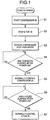
- Control of the prevention of the C fan from the refrigerant sleeping which is an embodiment of the present invention will be explained on the basis of the flow chart shown in FIG. 5 .
- step S11 whether the compressor 20 is driven or not is judged.
- the compressor 20 and the condenser 27 (hereinafter, referred to as the compressor and others) are not at high temperature, so that there is no need to cool them, and the process goes to a step S13, and the C fan 19 is put into a stop state.
- the process judges that the cooling is necessary and goes to a step S12.
- step S12 whether the air temperature detected by the air temperature sensor 53 is low, in this case, 10 DEG C or lower is judged.
- the air temperature is 10 DEG C or lower, that is, it is low, so that even if the compressor 20 is driven, the refrigerant sleeping is generated by the rotation of the C fan 19. Therefore, the process goes to the step S13, and the C fan 19 is put into the stop state.
- the process judges that the cooling of the compressor and others is necessary and goes to a step S14.
- step S14 whether the detection temperature of the outlet temperature sensor 56 is higher than the detection temperature of the inlet temperature sensor 55 by a predetermined value or more, in this case, 6 K or more is judged.
- a predetermined value or more in this case, 6 K or more
- the refrigerant is appropriately evaporated in the evaporator and the refrigerant sleeping is not generated, so that the process judges that the cooling of the compressor and others is necessary, goes to a step S15, and drives the C fan 19.
- a difference between the detection temperature of the outlet temperature sensor 56 and the detection temperature of the inlet temperature sensor 55 does not become a predetermined value or less, in this case, 3 K or less
- the process judges that the compressor and others are in an overcooled state and forcibly keeps the C fan 19 in the stop state, while when it becomes 3 K or less, the process judges that the compressor and others are returned to the normal state, goes to a step S18, cancels the forcible stop state of the C fan 19, and returns to the initial state.
- the control of the C fan even if the drive conditions of the C fan such as the driving of the compressor and the air temperature condition are realized, judges whether the refrigerant is sleeping in the compressor and the condenser and then drives the C fan. Therefore, the compressor and condenser are not overcooled, and the defective cooling due to the refrigerant sleeping can be prevented.
- the air temperature sensor is attached to the back of the cover 24, the temperature of the air taken in the machine room 22 can be detected accurately, thus the overcooling of the compressor and others due to the driving of the C fan can be prevented.
- step S21 whether the set temperature of the air which is a stop condition of the C fan 19 is set to a medium temperature, in this case, 20 DEG C is judged.
- the air temperature is low, it is set to 10 DEG C.
- the stop condition of the C fan 19 is set to 10 DEG C, the process goes to a step S22 and when the stop condition is set to 20 DEG C, the process goes to a step S23.
- step S22 whether the detection temperature of the outlet temperature sensor 56 is higher than the detection temperature of the inlet temperature sensor 55 by a predetermined value or more, in this case, 6 K or more is judged.
- the air temperature of the stop condition of the C fan 19 is set to 10 DEG C.
- the stop condition of the C fan 19 is set to an air temperature of 20 DEG C so that the C fan 19 is not at a high temperature the C fan 19 is not driven.
- the process goes to a step S26 and judges whether the compressor 20 is driven or not.
- the compressor 20 is not driven, the compressor and others will not become at a high temperature regardless of the air temperature and do need to be cooled, and then the process goes to a step S29 and puts the fan into the stop state.
- the process judges that the cooling is necessary and goes to a step S27.
- step S27 whether the air temperature detected by the air temperature sensor 52 is higher or not is judged as compared with the temperatures set at the steps S24 and S25
- the set temperature is set to 20 DEG C at the step S24 and the detected air temperature is a medium temperature of 16 DEG C
- the air temperature is lower than the set temperature, even when the air temperature is medium and the compressor 20 is driven, if the C fan 19 is rotated, there is a possibility of the generation of the refrigerant sleeping, so that the process goes to a step S29 and puts the C fan 19 into the stop state.
- the process goes to the step S24, keeps the set temperature of 20 DEG C. While when the inlet temperature is lower by 3 K or more, the process judges that there is no possibility of the generation of the refrigerant sleeping, goes to the step S25, and switches the setting temperature to 10 DEG C.
- the C fan control according to the present invention is particularly effective in a case where the refrigerant to be charged in a small amount such as a combustible cooling medium is used, and the defective cooling due to the refrigerant sleeping can be prevented.
- temperature sensors installed at the outlet and inlet of the F evaporator the refrigerant sleeping is detected.
- temperature sensors may also be installed respectively at the outlet and inlet of the R evaporator so as to detect the refrigerant sleeping.
- the set temperature and the temperature difference between at the outlet and the inlet of the F evaporator for detecting the refrigerant sleeping phenomenon vary with the refrigerating cycle and the capacity of the refrigerator, and needless to say, they are properly set to optimum temperatures.
- the operation and stop conditions of the C fan are not limited to those described above.
- the conditions may be combined with various conditions, such as during R flow, F flow and defrosting and the door switch.
- the C fan is effectively stopped for a predetermined period of time at the time of turning on power and at the time of starting the compressor, wherein the refrigerant sleeping is easily generated.
- the air temperature sensor is attached to the cover.
- the air temperature sensor may be installed in a place free of temperature effect of the compressor in the neighborhood of the machine room, such as on the rear cover or bottom plate.
- the air temperature sensor may be arranged on the downstream side of the refrigerant, or the condenser may be deformed, so as to avoid the effect of the temperature of the condenser, if possible.
- a refrigerator of the present invention even if a hydrocarbon cooling medium which is charged in a small amount and particularly soluble in refrigeration machine oil is used, the initial cooling performance after turning on power can be improved. Furthermore, defective cooling due to the sleeping of a refrigerant staying in the compressor or condenser can be prevented.
- the refrigerator according to this invention is widely usable for the household refrigerators.
Landscapes
- Engineering & Computer Science (AREA)
- Physics & Mathematics (AREA)
- Mechanical Engineering (AREA)
- Thermal Sciences (AREA)
- General Engineering & Computer Science (AREA)
- Chemical & Material Sciences (AREA)
- Combustion & Propulsion (AREA)
- Devices That Are Associated With Refrigeration Equipment (AREA)
Claims (1)
- Un réfrigérateur comportant un cycle frigorifique doté séquentiellement d'un compresseur (20), d'un condenseur (27), d'un mécanisme d'étirage, d'un évaporateur et d'un accumulateur, d'un capteur de température d'entrée (55) et d'un capteur de température de sortie (56) pour détecter des températures d'une entrée et d'une sortie dudit évaporateur, d'un capteur de température de l'air (53) pour détecter une température de l'air et d'un ventilateur de refroidissement (19) pour refroidir ledit compresseur, caractérisé en ce que ledit ventilateur de refroidissement est commandé par les étapes suivantes:une étape (S11) pour juger si le compresseur est entraîné ou pas;une étape (S12) pour juger si la température de l'air est élevée ou pas une fois qu'il est jugé par l'étape précédente que ledit compresseur est entraîné;une étape (S13) pour arrêter le ventilateur de refroidissement lorsqu'il est jugé que le compresseur n'est pas entraîné ou que la température de l'air n'est pas élevée;une étape (S14) pour juger si une différence de température entre une température détectée par ledit capteur de température d'entrée et une température détectée par ledit capteur de température de sortie est égale ou supérieure à une première valeur prédéterminée une fois qu'il est jugé que ladite température de l'air est élevée ;une étape (S15) pour entraîner le ventilateur de refroidissement lorsqu'il est jugé que ladite différence de température entre lesdites températures détectées par lesdits capteurs de température est inférieure à une première valeur prédéterminée;une étape (S16) pour arrêter de manière forcée le ventilateur de refroidissement lorsqu'il est jugé que ladite différence de température entre lesdites températures détectées par lesdits capteurs de température est égale ou supérieure à ladite première valeur prédéterminée;une étape (S17) pour juger après l'étape précédente, que ladite différence de température entre lesdites températures détectées par lesdits capteurs de température soit égale ou inférieure à une seconde valeur prédéterminée qui est inférieure à ladite première valeur prédéterminée; etune étape (S18) pour annuler un état d'arrêt forcé du ventilateur de refroidissement une fois qu'il est jugé par l'étape précédente que la différence de température entre les températures détectées par les capteurs de température est égale ou inférieure à ladite seconde valeur prédéterminée.
Applications Claiming Priority (5)
| Application Number | Priority Date | Filing Date | Title |
|---|---|---|---|
| JP2002093672A JP2003287334A (ja) | 2002-03-29 | 2002-03-29 | 冷蔵庫 |
| JP2002093672 | 2002-03-29 | ||
| JP2002093671A JP2003287333A (ja) | 2002-03-29 | 2002-03-29 | 冷蔵庫 |
| JP2002093671 | 2002-03-29 | ||
| PCT/JP2003/003775 WO2003083388A1 (fr) | 2002-03-29 | 2003-03-27 | Refrigerateur |
Publications (3)
| Publication Number | Publication Date |
|---|---|
| EP1496322A1 EP1496322A1 (fr) | 2005-01-12 |
| EP1496322A4 EP1496322A4 (fr) | 2010-12-29 |
| EP1496322B1 true EP1496322B1 (fr) | 2017-06-14 |
Family
ID=28677570
Family Applications (1)
| Application Number | Title | Priority Date | Filing Date |
|---|---|---|---|
| EP03715460.6A Expired - Lifetime EP1496322B1 (fr) | 2002-03-29 | 2003-03-27 | Refrigerateur |
Country Status (5)
| Country | Link |
|---|---|
| US (1) | US7448226B2 (fr) |
| EP (1) | EP1496322B1 (fr) |
| KR (1) | KR100586576B1 (fr) |
| CN (1) | CN100441984C (fr) |
| WO (1) | WO2003083388A1 (fr) |
Families Citing this family (64)
| Publication number | Priority date | Publication date | Assignee | Title |
|---|---|---|---|---|
| US7770406B2 (en) * | 2003-11-28 | 2010-08-10 | Kabushiki Kaisha Toshiba | Refrigerator |
| JP4600212B2 (ja) * | 2005-08-23 | 2010-12-15 | 株式会社デンソー | 超臨界冷凍サイクル装置 |
| KR100701769B1 (ko) * | 2005-10-28 | 2007-03-30 | 엘지전자 주식회사 | 공기조화기의 제어방법 |
| WO2008041996A1 (fr) * | 2006-10-06 | 2008-04-10 | Carrier Corporation | Système réfrigérant avec compresseur à modulation d'impulsions en durée à vitesse multiple |
| KR100845857B1 (ko) | 2006-12-26 | 2008-07-14 | 엘지전자 주식회사 | 냉동사이클장치와 이를 구비하는 냉장고 및 그 제어방법 |
| DE202007017691U1 (de) * | 2007-10-08 | 2009-02-26 | Liebherr-Hausgeräte Ochsenhausen GmbH | Kühl- und/oder Gefriergerät |
| KR101698080B1 (ko) * | 2009-09-14 | 2017-02-01 | 엘지전자 주식회사 | 제빙기를 갖는 이동식 냉장고 |
| KR20110072441A (ko) * | 2009-12-22 | 2011-06-29 | 삼성전자주식회사 | 냉장고 및 그 운전 제어 방법 |
| BRPI1005090A2 (pt) | 2010-12-10 | 2013-04-02 | Whirlpool Sa | mÉtodos de controle de compressor com dupla sucÇço para sistemas de refrigeraÇço |
| JP5786225B2 (ja) * | 2011-03-14 | 2015-09-30 | 株式会社テージーケー | 膨張弁 |
| US20120266619A1 (en) * | 2011-04-21 | 2012-10-25 | Bradley Douglas Shaw | Cooling system for use in an appliance and method of assembling same |
| US9285153B2 (en) | 2011-10-19 | 2016-03-15 | Thermo Fisher Scientific (Asheville) Llc | High performance refrigerator having passive sublimation defrost of evaporator |
| US9310121B2 (en) | 2011-10-19 | 2016-04-12 | Thermo Fisher Scientific (Asheville) Llc | High performance refrigerator having sacrificial evaporator |
| US9696077B2 (en) * | 2012-02-21 | 2017-07-04 | Whirlpool Corporation | Dual capillary tube / heat exchanger in combination with cycle priming for reducing charge migration |
| US9285161B2 (en) * | 2012-02-21 | 2016-03-15 | Whirlpool Corporation | Refrigerator with variable capacity compressor and cycle priming action through capacity control and associated methods |
| US9618246B2 (en) * | 2012-02-21 | 2017-04-11 | Whirlpool Corporation | Refrigeration arrangement and methods for reducing charge migration |
| US9221210B2 (en) | 2012-04-11 | 2015-12-29 | Whirlpool Corporation | Method to create vacuum insulated cabinets for refrigerators |
| US9182158B2 (en) | 2013-03-15 | 2015-11-10 | Whirlpool Corporation | Dual cooling systems to minimize off-cycle migration loss in refrigerators with a vacuum insulated structure |
| US8986483B2 (en) | 2012-04-02 | 2015-03-24 | Whirlpool Corporation | Method of making a folded vacuum insulated structure |
| CN104321601B (zh) * | 2012-05-18 | 2016-07-06 | 松下知识产权经营株式会社 | 冷藏库 |
| JP5310911B1 (ja) * | 2012-06-13 | 2013-10-09 | ダイキン工業株式会社 | 冷凍装置 |
| US9046094B2 (en) | 2012-08-24 | 2015-06-02 | Whirlpool Corporation | Refrigerator with energy consumption optimization using adaptive fan delay |
| US9599392B2 (en) | 2014-02-24 | 2017-03-21 | Whirlpool Corporation | Folding approach to create a 3D vacuum insulated door from 2D flat vacuum insulation panels |
| US9689604B2 (en) | 2014-02-24 | 2017-06-27 | Whirlpool Corporation | Multi-section core vacuum insulation panels with hybrid barrier film envelope |
| US10052819B2 (en) | 2014-02-24 | 2018-08-21 | Whirlpool Corporation | Vacuum packaged 3D vacuum insulated door structure and method therefor using a tooling fixture |
| KR101677649B1 (ko) * | 2014-12-23 | 2016-11-18 | 엘지전자 주식회사 | 냉장고 |
| US9476633B2 (en) | 2015-03-02 | 2016-10-25 | Whirlpool Corporation | 3D vacuum panel and a folding approach to create the 3D vacuum panel from a 2D vacuum panel of non-uniform thickness |
| US10161669B2 (en) | 2015-03-05 | 2018-12-25 | Whirlpool Corporation | Attachment arrangement for vacuum insulated door |
| US9897370B2 (en) | 2015-03-11 | 2018-02-20 | Whirlpool Corporation | Self-contained pantry box system for insertion into an appliance |
| US9441779B1 (en) | 2015-07-01 | 2016-09-13 | Whirlpool Corporation | Split hybrid insulation structure for an appliance |
| US11052579B2 (en) | 2015-12-08 | 2021-07-06 | Whirlpool Corporation | Method for preparing a densified insulation material for use in appliance insulated structure |
| US10041724B2 (en) | 2015-12-08 | 2018-08-07 | Whirlpool Corporation | Methods for dispensing and compacting insulation materials into a vacuum sealed structure |
| US12508751B2 (en) | 2015-12-08 | 2025-12-30 | Whirlpool Corporation | Insulation compaction device and method for forming an insulated structure for an appliance |
| US10422573B2 (en) | 2015-12-08 | 2019-09-24 | Whirlpool Corporation | Insulation structure for an appliance having a uniformly mixed multi-component insulation material, and a method for even distribution of material combinations therein |
| US10222116B2 (en) | 2015-12-08 | 2019-03-05 | Whirlpool Corporation | Method and apparatus for forming a vacuum insulated structure for an appliance having a pressing mechanism incorporated within an insulation delivery system |
| US10429125B2 (en) | 2015-12-08 | 2019-10-01 | Whirlpool Corporation | Insulation structure for an appliance having a uniformly mixed multi-component insulation material, and a method for even distribution of material combinations therein |
| US10422569B2 (en) | 2015-12-21 | 2019-09-24 | Whirlpool Corporation | Vacuum insulated door construction |
| US9840042B2 (en) | 2015-12-22 | 2017-12-12 | Whirlpool Corporation | Adhesively secured vacuum insulated panels for refrigerators |
| US9752818B2 (en) | 2015-12-22 | 2017-09-05 | Whirlpool Corporation | Umbilical for pass through in vacuum insulated refrigerator structures |
| US10018406B2 (en) | 2015-12-28 | 2018-07-10 | Whirlpool Corporation | Multi-layer gas barrier materials for vacuum insulated structure |
| US10610985B2 (en) | 2015-12-28 | 2020-04-07 | Whirlpool Corporation | Multilayer barrier materials with PVD or plasma coating for vacuum insulated structure |
| US10030905B2 (en) | 2015-12-29 | 2018-07-24 | Whirlpool Corporation | Method of fabricating a vacuum insulated appliance structure |
| US10807298B2 (en) | 2015-12-29 | 2020-10-20 | Whirlpool Corporation | Molded gas barrier parts for vacuum insulated structure |
| US11247369B2 (en) | 2015-12-30 | 2022-02-15 | Whirlpool Corporation | Method of fabricating 3D vacuum insulated refrigerator structure having core material |
| DE112017000559T5 (de) * | 2016-01-29 | 2018-11-08 | Lg Electronics Inc. | Kühlschrank |
| US11009284B2 (en) | 2016-04-15 | 2021-05-18 | Whirlpool Corporation | Vacuum insulated refrigerator structure with three dimensional characteristics |
| EP3443285B1 (fr) | 2016-04-15 | 2021-03-10 | Whirlpool Corporation | Armoire de réfrigérateur à isolation sous vide |
| US11320193B2 (en) | 2016-07-26 | 2022-05-03 | Whirlpool Corporation | Vacuum insulated structure trim breaker |
| WO2018034665A1 (fr) | 2016-08-18 | 2018-02-22 | Whirlpool Corporation | Compartiment de machine pour une structure isolée sous vide |
| US11175080B2 (en) * | 2016-10-28 | 2021-11-16 | Mitsubishi Electric Corporation | Refrigeration cycle apparatus having heat exchanger switchable between parallel and series connection |
| KR102723276B1 (ko) * | 2016-11-10 | 2024-10-31 | 엘지전자 주식회사 | 냉장고 및 냉장고의 제어 방법 |
| KR102725966B1 (ko) | 2016-11-11 | 2024-11-05 | 엘지전자 주식회사 | 냉장고 및 그 제어 방법 |
| US10598424B2 (en) | 2016-12-02 | 2020-03-24 | Whirlpool Corporation | Hinge support assembly |
| KR102409514B1 (ko) * | 2017-11-01 | 2022-06-16 | 엘지전자 주식회사 | 냉장고 및 그의 제어방법 |
| US11473830B2 (en) | 2018-03-09 | 2022-10-18 | Electrolux Do Brasil S.A. | Adaptive defrost activation method |
| US10907888B2 (en) | 2018-06-25 | 2021-02-02 | Whirlpool Corporation | Hybrid pigmented hot stitched color liner system |
| US12352472B2 (en) * | 2019-07-02 | 2025-07-08 | Heatcraft Refrigeration Products Llc | Cooling system |
| CN112097411B (zh) * | 2020-10-23 | 2022-02-25 | 长虹美菱股份有限公司 | 一种变频冰箱的双循环制冷系统及其控制方法 |
| KR102412061B1 (ko) * | 2020-11-30 | 2022-06-23 | 엘지전자 주식회사 | 냉장고 및 냉장고 제어 방법 |
| CN114719554A (zh) * | 2021-01-06 | 2022-07-08 | 青岛海尔电冰箱有限公司 | 冰箱的控制方法与冰箱 |
| KR20220132305A (ko) | 2021-03-23 | 2022-09-30 | 삼성전자주식회사 | 냉장고 및 그 제어 방법 |
| US12140359B2 (en) | 2021-10-21 | 2024-11-12 | Copeland Lp | Climate control systems for use with high glide working fluids and methods for operation thereof |
| CN114562851A (zh) * | 2022-03-28 | 2022-05-31 | 长虹美菱股份有限公司 | 一种冰箱及其化霜控制方法 |
| US12320569B2 (en) | 2022-11-17 | 2025-06-03 | Copeland Lp | Climate control systems having ejector cooling for use with moderate to high glide working fluids and methods for operation thereof |
Family Cites Families (20)
| Publication number | Priority date | Publication date | Assignee | Title |
|---|---|---|---|---|
| JPS4614447Y1 (fr) | 1968-03-12 | 1971-05-21 | ||
| JPS5944551A (ja) | 1982-09-06 | 1984-03-13 | 株式会社東芝 | 冷蔵庫 |
| JPS63297981A (ja) | 1987-05-29 | 1988-12-05 | 松下冷機株式会社 | 冷蔵貯蔵庫 |
| US5150584A (en) * | 1991-09-26 | 1992-09-29 | General Motors Corporation | Method and apparatus for detecting low refrigerant charge |
| JP2822719B2 (ja) * | 1991-09-26 | 1998-11-11 | 三菱電機株式会社 | 冷蔵庫 |
| JPH0735455A (ja) * | 1993-07-19 | 1995-02-07 | Matsushita Refrig Co Ltd | 冷蔵庫の圧縮機冷却用ファンの制御装置 |
| JPH0791791A (ja) * | 1993-09-21 | 1995-04-04 | Matsushita Refrig Co Ltd | 冷蔵庫 |
| JPH0791717A (ja) * | 1993-09-24 | 1995-04-04 | Hitachi Ltd | 空気調和機 |
| JPH07146054A (ja) * | 1993-11-26 | 1995-06-06 | Toshiba Corp | 冷蔵庫 |
| JPH07260313A (ja) * | 1994-03-22 | 1995-10-13 | Toshiba Corp | 冷蔵庫 |
| JP3731214B2 (ja) * | 1994-07-20 | 2006-01-05 | ダイキン工業株式会社 | 圧縮機の液冷媒排出装置 |
| JPH0933123A (ja) * | 1995-07-19 | 1997-02-07 | Daikin Ind Ltd | 極低温冷凍装置 |
| JPH1047827A (ja) | 1996-08-06 | 1998-02-20 | Matsushita Refrig Co Ltd | 冷凍冷蔵庫 |
| JPH10197126A (ja) * | 1997-01-08 | 1998-07-31 | Mitsubishi Electric Corp | 冷凍冷蔵庫の制御装置 |
| CN1203353A (zh) * | 1997-06-25 | 1998-12-30 | 大宇电子株式会社 | 冰箱的制冷系统 |
| JP3598809B2 (ja) * | 1997-08-25 | 2004-12-08 | 三菱電機株式会社 | 冷凍サイクル装置 |
| JP3716897B2 (ja) * | 1998-02-12 | 2005-11-16 | 三洋電機株式会社 | 冷蔵庫 |
| JPH11230627A (ja) | 1998-02-17 | 1999-08-27 | Matsushita Electric Ind Co Ltd | 冷凍サイクル装置 |
| JP4056151B2 (ja) | 1998-11-16 | 2008-03-05 | カルソニックカンセイ株式会社 | ヒートポンプ式空気調和装置 |
| JP4327936B2 (ja) * | 1999-04-08 | 2009-09-09 | 三菱電機株式会社 | ヒートポンプ式冷凍装置 |
-
2003
- 2003-03-27 US US10/509,637 patent/US7448226B2/en not_active Expired - Fee Related
- 2003-03-27 CN CNB038072297A patent/CN100441984C/zh not_active Expired - Fee Related
- 2003-03-27 KR KR1020047015304A patent/KR100586576B1/ko not_active Expired - Fee Related
- 2003-03-27 WO PCT/JP2003/003775 patent/WO2003083388A1/fr not_active Ceased
- 2003-03-27 EP EP03715460.6A patent/EP1496322B1/fr not_active Expired - Lifetime
Also Published As
| Publication number | Publication date |
|---|---|
| US20050223722A1 (en) | 2005-10-13 |
| KR100586576B1 (ko) | 2006-06-07 |
| US7448226B2 (en) | 2008-11-11 |
| WO2003083388A1 (fr) | 2003-10-09 |
| EP1496322A4 (fr) | 2010-12-29 |
| CN100441984C (zh) | 2008-12-10 |
| CN1643317A (zh) | 2005-07-20 |
| EP1496322A1 (fr) | 2005-01-12 |
| KR20040094875A (ko) | 2004-11-10 |
Similar Documents
| Publication | Publication Date | Title |
|---|---|---|
| US7448226B2 (en) | Refrigerator | |
| KR870001533B1 (ko) | 냉장고 | |
| KR100586575B1 (ko) | 냉장고 | |
| KR20120012613A (ko) | 냉장고 및 그 제어방법 | |
| EP2142869B1 (fr) | Procédé de commande d'un réfrigérateur | |
| TW574493B (en) | Refrigerator | |
| JP3455058B2 (ja) | 冷蔵庫 | |
| JP5105276B2 (ja) | 冷蔵庫 | |
| JP2003287333A (ja) | 冷蔵庫 | |
| KR100471063B1 (ko) | 냉장고 및 그 제어방법 | |
| KR20190095804A (ko) | 냉장고 및 그 운전방법 | |
| JP2002206840A (ja) | 冷蔵庫 | |
| JP2009085552A (ja) | 冷蔵庫 | |
| KR100207086B1 (ko) | 냉장고의 제상운전 제어방법 | |
| JPH0618145A (ja) | 低温ショーケース | |
| KR19990004645A (ko) | 냉장고의 구동제어방법 | |
| KR20170091198A (ko) | 드레인 장치 및 드레인 장치 제어 방법 | |
| KR100213718B1 (ko) | 냉장고의 제상방법 | |
| KR100237705B1 (ko) | 냉장고의 제상운전 제어방법 | |
| JP2004092961A (ja) | 冷蔵庫 | |
| KR20050063258A (ko) | 냉장고의 송풍팬 운전 제어방법 | |
| KR100191536B1 (ko) | 냉장고의 압축기제어장치 및 그 방법 | |
| KR0171505B1 (ko) | 쇼케이스의 응축기 먼지제거방법 | |
| JP2003287334A (ja) | 冷蔵庫 | |
| JP3192730B2 (ja) | 冷蔵庫 |
Legal Events
| Date | Code | Title | Description |
|---|---|---|---|
| PUAI | Public reference made under article 153(3) epc to a published international application that has entered the european phase |
Free format text: ORIGINAL CODE: 0009012 |
|
| 17P | Request for examination filed |
Effective date: 20041027 |
|
| AK | Designated contracting states |
Kind code of ref document: A1 Designated state(s): DE GB IT |
|
| RIN1 | Information on inventor provided before grant (corrected) |
Inventor name: TAKAGI, YASUSHI Inventor name: HORIE, MUNEHIRO Inventor name: SAKUMA, TSUTOMU Inventor name: SARUTA, SUSUMU Inventor name: YAMASHITA, JUN |
|
| A4 | Supplementary search report drawn up and despatched |
Effective date: 20101130 |
|
| 17Q | First examination report despatched |
Effective date: 20141222 |
|
| RAP1 | Party data changed (applicant data changed or rights of an application transferred) |
Owner name: TOSHIBA LIFESTYLE PRODUCTS & SERVICES CORPORATION |
|
| GRAP | Despatch of communication of intention to grant a patent |
Free format text: ORIGINAL CODE: EPIDOSNIGR1 |
|
| INTG | Intention to grant announced |
Effective date: 20170203 |
|
| GRAC | Information related to communication of intention to grant a patent modified |
Free format text: ORIGINAL CODE: EPIDOSCIGR1 |
|
| INTG | Intention to grant announced |
Effective date: 20170215 |
|
| GRAS | Grant fee paid |
Free format text: ORIGINAL CODE: EPIDOSNIGR3 |
|
| GRAA | (expected) grant |
Free format text: ORIGINAL CODE: 0009210 |
|
| AK | Designated contracting states |
Kind code of ref document: B1 Designated state(s): DE GB IT |
|
| REG | Reference to a national code |
Ref country code: GB Ref legal event code: FG4D |
|
| REG | Reference to a national code |
Ref country code: DE Ref legal event code: R096 Ref document number: 60350323 Country of ref document: DE |
|
| REG | Reference to a national code |
Ref country code: DE Ref legal event code: R097 Ref document number: 60350323 Country of ref document: DE |
|
| PLBE | No opposition filed within time limit |
Free format text: ORIGINAL CODE: 0009261 |
|
| STAA | Information on the status of an ep patent application or granted ep patent |
Free format text: STATUS: NO OPPOSITION FILED WITHIN TIME LIMIT |
|
| 26N | No opposition filed |
Effective date: 20180315 |
|
| PGFP | Annual fee paid to national office [announced via postgrant information from national office to epo] |
Ref country code: DE Payment date: 20200317 Year of fee payment: 18 Ref country code: GB Payment date: 20200318 Year of fee payment: 18 Ref country code: IT Payment date: 20200221 Year of fee payment: 18 |
|
| REG | Reference to a national code |
Ref country code: DE Ref legal event code: R082 Ref document number: 60350323 Country of ref document: DE Representative=s name: HL KEMPNER PATENTANWALT, RECHTSANWALT, SOLICIT, DE |
|
| REG | Reference to a national code |
Ref country code: DE Ref legal event code: R119 Ref document number: 60350323 Country of ref document: DE |
|
| GBPC | Gb: european patent ceased through non-payment of renewal fee |
Effective date: 20210327 |
|
| PG25 | Lapsed in a contracting state [announced via postgrant information from national office to epo] |
Ref country code: GB Free format text: LAPSE BECAUSE OF NON-PAYMENT OF DUE FEES Effective date: 20210327 Ref country code: DE Free format text: LAPSE BECAUSE OF NON-PAYMENT OF DUE FEES Effective date: 20211001 |
|
| PG25 | Lapsed in a contracting state [announced via postgrant information from national office to epo] |
Ref country code: IT Free format text: LAPSE BECAUSE OF NON-PAYMENT OF DUE FEES Effective date: 20210327 |