EP1496531A2 - Dispositif de capteur pour détecter un mouvement de déclenchement - Google Patents
Dispositif de capteur pour détecter un mouvement de déclenchement Download PDFInfo
- Publication number
- EP1496531A2 EP1496531A2 EP04015844A EP04015844A EP1496531A2 EP 1496531 A2 EP1496531 A2 EP 1496531A2 EP 04015844 A EP04015844 A EP 04015844A EP 04015844 A EP04015844 A EP 04015844A EP 1496531 A2 EP1496531 A2 EP 1496531A2
- Authority
- EP
- European Patent Office
- Prior art keywords
- sensor
- trigger
- regions
- sensor device
- areas
- Prior art date
- Legal status (The legal status is an assumption and is not a legal conclusion. Google has not performed a legal analysis and makes no representation as to the accuracy of the status listed.)
- Withdrawn
Links
- 230000003287 optical effect Effects 0.000 claims description 16
- 238000001514 detection method Methods 0.000 claims description 11
- 230000001939 inductive effect Effects 0.000 claims description 4
- 238000009434 installation Methods 0.000 claims description 2
- 238000011156 evaluation Methods 0.000 description 3
- 230000009286 beneficial effect Effects 0.000 description 2
- 238000010411 cooking Methods 0.000 description 2
- 241001523162 Helle Species 0.000 description 1
- 238000010438 heat treatment Methods 0.000 description 1
- 230000002085 persistent effect Effects 0.000 description 1
Images
Classifications
-
- G—PHYSICS
- G01—MEASURING; TESTING
- G01D—MEASURING NOT SPECIALLY ADAPTED FOR A SPECIFIC VARIABLE; ARRANGEMENTS FOR MEASURING TWO OR MORE VARIABLES NOT COVERED IN A SINGLE OTHER SUBCLASS; TARIFF METERING APPARATUS; MEASURING OR TESTING NOT OTHERWISE PROVIDED FOR
- G01D5/00—Mechanical means for transferring the output of a sensing member; Means for converting the output of a sensing member to another variable where the form or nature of the sensing member does not constrain the means for converting; Transducers not specially adapted for a specific variable
- G01D5/12—Mechanical means for transferring the output of a sensing member; Means for converting the output of a sensing member to another variable where the form or nature of the sensing member does not constrain the means for converting; Transducers not specially adapted for a specific variable using electric or magnetic means
- G01D5/244—Mechanical means for transferring the output of a sensing member; Means for converting the output of a sensing member to another variable where the form or nature of the sensing member does not constrain the means for converting; Transducers not specially adapted for a specific variable using electric or magnetic means influencing characteristics of pulses or pulse trains; generating pulses or pulse trains
- G01D5/249—Mechanical means for transferring the output of a sensing member; Means for converting the output of a sensing member to another variable where the form or nature of the sensing member does not constrain the means for converting; Transducers not specially adapted for a specific variable using electric or magnetic means influencing characteristics of pulses or pulse trains; generating pulses or pulse trains using pulse code
- G01D5/2492—Pulse stream
-
- G—PHYSICS
- G01—MEASURING; TESTING
- G01D—MEASURING NOT SPECIALLY ADAPTED FOR A SPECIFIC VARIABLE; ARRANGEMENTS FOR MEASURING TWO OR MORE VARIABLES NOT COVERED IN A SINGLE OTHER SUBCLASS; TARIFF METERING APPARATUS; MEASURING OR TESTING NOT OTHERWISE PROVIDED FOR
- G01D5/00—Mechanical means for transferring the output of a sensing member; Means for converting the output of a sensing member to another variable where the form or nature of the sensing member does not constrain the means for converting; Transducers not specially adapted for a specific variable
- G01D5/12—Mechanical means for transferring the output of a sensing member; Means for converting the output of a sensing member to another variable where the form or nature of the sensing member does not constrain the means for converting; Transducers not specially adapted for a specific variable using electric or magnetic means
- G01D5/25—Selecting one or more conductors or channels from a plurality of conductors or channels, e.g. by closing contacts
-
- H—ELECTRICITY
- H01—ELECTRIC ELEMENTS
- H01H—ELECTRIC SWITCHES; RELAYS; SELECTORS; EMERGENCY PROTECTIVE DEVICES
- H01H19/00—Switches operated by an operating part which is rotatable about a longitudinal axis thereof and which is acted upon directly by a solid body external to the switch, e.g. by a hand
- H01H19/005—Electromechanical pulse generators
-
- H—ELECTRICITY
- H03—ELECTRONIC CIRCUITRY
- H03M—CODING; DECODING; CODE CONVERSION IN GENERAL
- H03M1/00—Analogue/digital conversion; Digital/analogue conversion
- H03M1/12—Analogue/digital converters
- H03M1/22—Analogue/digital converters pattern-reading type
- H03M1/24—Analogue/digital converters pattern-reading type using relatively movable reader and disc or strip
- H03M1/28—Analogue/digital converters pattern-reading type using relatively movable reader and disc or strip with non-weighted coding
- H03M1/30—Analogue/digital converters pattern-reading type using relatively movable reader and disc or strip with non-weighted coding incremental
- H03M1/301—Constructional details of parts relevant to the encoding mechanism, e.g. pattern carriers, pattern sensors
-
- H—ELECTRICITY
- H01—ELECTRIC ELEMENTS
- H01H—ELECTRIC SWITCHES; RELAYS; SELECTORS; EMERGENCY PROTECTIVE DEVICES
- H01H19/00—Switches operated by an operating part which is rotatable about a longitudinal axis thereof and which is acted upon directly by a solid body external to the switch, e.g. by a hand
- H01H19/005—Electromechanical pulse generators
- H01H2019/006—Electromechanical pulse generators being rotation direction sensitive, e.g. the generated pulse or code depends on the direction of rotation of the operating part
Definitions
- the invention relates to a sensor device according to the preamble of claim 1 for detecting a release movement, wherein a Sensor and an elongated or elongated sensor trigger provided are that work together.
- a sensor trigger for example essentially straight or round or circular be.
- a relative movement take place in both directions of length or longitudinal extent.
- a rotary knob is known. It essentially corresponds an aforementioned slider, the basic principle the linear movement is converted into a rotational movement.
- the invention is based on the object, an aforementioned sensor device to develop further with new functionalities, which in particular has a simplified structure.
- the sensor trigger of the sensor device mentioned above with a sequence of tripping areas and intermediate areas provided, wherein the areas each provided alternately are.
- the sensor trigger or the triggering areas are according to the invention formed such that they are not mirror-symmetrical to a Mirror axis, which transverse to the longitudinal extent of the sensor trigger or transverse to the direction of the relative movement.
- This non-mirror-symmetrical design of the sensor release with the trigger areas and intermediate areas has the advantage that in the basic assumption of an approximately constant speed the relative movement due to the sequence of tripping areas and intermediate areas, which due to the lack of mirror symmetry are each different lengths, a detection of the direction of movement is possible.
- a Control device which for the control and evaluation of Sensor is responsible, only needs the pattern of the sensor trigger be deposited to depend on the direction of relative motion close the times of triggering the sensor.
- the trigger areas alternately are longer and shorter.
- the difference in length can be a factor of 2 to 5, preferably 3 to 4, amount.
- Particularly preferred are the Intermediate areas alternately longer and shorter.
- the difference in length between long intermediate areas and short intermediate areas be significantly larger, for example, two to ten times be.
- a short intermediate area is about as short as a short trip area.
- the long intermediate regions are advantageously longer, in particular several times longer than the long trigger areas.
- lengths are taken in the millimeter range. So, for example a short trip area or intermediate area a length which lies between 1 mm and 5 mm. For example, you can it can be between 2mm and 3mm.
- the long trip areas or intermediate areas have a length between 5mm and 20mm.
- the long tripping areas for example, have a length between 5mm and 10mm on, the long intermediate areas between, for example 10mm and 15mm.
- the sensor trigger is advantageously a straight and consistently wider Strips.
- the regions each extend transversely to the longitudinal direction of the sensor release.
- the direction of the relative movement between him and the sensor is particularly advantageous exactly along its Longitudinal axis.
- the sensor trigger be curved, curved or circular. He is advantageously circular, so that it forms a closed circle. So can create an endless sensor trigger in its extension become. It is advantageously used in a rotary control.
- the type of sensor detection Preferred is an optical detection.
- the sensor trigger can have optically different areas than tripping areas and intermediate areas. For example, they can be both bright and on the other hand be dark or on the other hand reflective and on the other hand frosted.
- the sensor in turn is advantageous in an optical sensor device designed for brightness scanning. He can do this for one Have light emitter and a light receiver.
- the light transmitter emits light against the sensor trigger.
- the sensor on the one hand the highest possible sensor triggering having. This allows the areas to be relatively narrow train. This is the sequence of regions in the relative movement by an operator relatively quickly, so that, too Speed differences detected and taken into account in the evaluation can be.
- the sensor is advantageously connected to a controller, which due to the duration of detection of a trip area or an intermediate area Recognize the speed of relative movement or can calculate. Furthermore, it can be recognized with the controller like the sequence of different long trigger ranges and different long intermediate areas. Is this pattern known Can thus on the direction and distance of the relative movement getting closed. This allows a total of one Determination of the tripping movement with regard to path. Should by the Tripping motion a setting of different points or levels These can advantageously be one or more times shorter or long trip ranges.
- a possible application example of a sensor device according to the invention is an installation in a slider controller, which is a non-contact Detection has.
- a slider or knob can be used very diverse, for example as a power adjuster for electrical appliances, such as hobs with a variety of cooking stages, for example nine cooking stages.
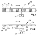
- a sensor device 11a has a sensor trigger 13a on in elongated strip form.
- the sensor trigger 13a on the one hand, has long intermediate regions 15a and short intermediate regions 16a on. Furthermore, it has long trip areas 18a and short trip areas 19a. These are provided alternately, as shown in FIG. 1. It can be seen how intermediate regions 15a or 16a and trigger areas 18a and 19a alternate. Furthermore, it is the sequence shown the one that is next to a long intermediate area 15a a long trip area 18a is arranged. Then comes a short intermediate region 16a and a short trigger region 19a, etc.
- the various types of intermediate areas or triggering areas have each exactly the same length.
- an optical sensor 21 is provided for detection or optical scanning of the sensor trigger 13a.
- the optical sensor 21 is connected to a controller 23 a, which controls it and evaluates its signals.
- the optical sensor 21 should be small even with respect to the width of the short intermediate regions 16a and short Tripping areas 19a. This is important for the tripping accuracy.
- the optical sensor 21 may be, for example, a reflection function exhibit. This means that either externally irradiated Light from the sensor trigger 13a, depending on the intermediate area or Trip range, reflected differently and detected by the sensor 21 and evaluated. Furthermore, the optical sensor 21 even a corresponding light source and a corresponding light receiver exhibit.
- a reflective sensor trigger 13a could at a optically working detection also a different translucent Sensor release can be used.
- he can with a Through-photoelectric switch can be used.
- triggering regions 18a and 19a could also be used Magnets are used. Instead of the optical sensor 21a would then a Hall sensor can be used. Likewise, inductive or be provided capacitive tripping areas.
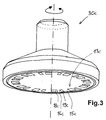
- the sensor trigger 13b is again in long intermediate areas 15b and short intermediate areas 16b and long trip areas 18b and short trip areas 19b divided. As can be clearly seen, these are in protrusions and / or depressions, wherein the trigger areas 18b and 19b form the projections.
- a scanner 24 As a sensor for mechanical scanning, a scanner 24 is provided, which is pressed elastically against the sensor trigger 13b.
- the scanner 24 is connected to a switch 25b and a controller 23b, that he closes the switch depending on whether he is on an intermediate region or a triggering region is present.
- FIG 3 is in the representation of obliquely below a so-called rotary knob 30c shown.
- a rotary knob is for example off EP 797 227 A, to which expressly incorporated herein by reference becomes.
- a rotation about a dot-dash vertical Axis should be made a setting, for example for adjusting the power supply in a radiant heating of a Cooktop.
- a sensor trigger 13c in Circular shape arranged.
- the sensor trigger 13c in long and short intermediate areas 15c and 16c as well divided long and short trip areas 18c and 19c. Basically corresponds to the sensor trigger 13c of an arrangement according to Figure 1, only just not in a straight shape but in a round or circular shape.
- the mounting of the rotary knob 30c can, as in the above-mentioned EP 797 227 A, done magnetically and not with a rigid Axis. In this respect, although by magnetic forces certain persistent effects given along the axis of rotation. However, these forces are not too big either. In this respect, it is in such a rotary knob 30c or in such a sensor device 11c advantageous, no to use mechanical scanning. Otherwise, however, are the previously mentioned options available, namely magnetically means Hall sensors, capacitive or inductive as well as optical. Alternatively it is possible, the rotary knob 30c with a fixed axis of rotation or pivot bearing to provide.
- the sensor device 11c differs according to FIG. 3, in principle not from those of FIGS. 1 and 2. What was there for the straightforward education and a move along this extension direction is true with respect to the sensor device 11c valid according to Figure 3 in the circumferential direction.
- a sensor trigger 13 is in long and short intermediate areas 15 and 16 as well as long and short trip areas Split 18 and 19. To distinguish these different Areas is a sensor provided.
- the triggering capacity of the sensor should be below the shortest width of one of the areas.
- the sensor trigger Based on the position between sensor trigger 13 and sensor 21 or scanner 24, the sensor trigger as a moving part, for example moved to the right. Then, the optical sensor 21 detects First, the left of him lying short tripping area 19a and gives a corresponding signal to the controller 23a. Then drives short intermediate region 16a past the sensor 21, again followed from a long trip area 18a. Then comes a long one Intermediate area 15a and then again a short trip area 19a. Because the respective dimensions of the intermediate areas and tripping areas can be stored or known in the controller 23a due to the times with which the different areas alternate or the resulting triggers, on the speed closed the relative movement.
- the relative movement From the order of the different areas or one of these triggers or not in the direction closed the relative movement. First comes a short one Trigger area and then a short intermediate area and then a long one Tripping area and then a long intermediate area, so runs the Sensor trigger 13a compared to the sensor 21 to the right. Is the The other way around, the sensor trigger 13a runs to the left. The same applies to the sensor trigger 13b of the sensor device 11b.
- the dimensions of the different tripping areas and intermediate areas in relation to the sensor release as well as the total movement should be such that the desired release of the relative movement not too tight. For a safe release of it should be can be assumed that the speed of relative motion does not fluctuate too much, or if it fluctuates, then only in each case after passing through a complete sequence of intermediate areas and trip areas.
Landscapes
- Physics & Mathematics (AREA)
- General Physics & Mathematics (AREA)
- Engineering & Computer Science (AREA)
- Theoretical Computer Science (AREA)
- Geophysics And Detection Of Objects (AREA)
- Portable Nailing Machines And Staplers (AREA)
Applications Claiming Priority (2)
| Application Number | Priority Date | Filing Date | Title |
|---|---|---|---|
| DE10330912 | 2003-07-07 | ||
| DE2003130912 DE10330912A1 (de) | 2003-07-07 | 2003-07-07 | Sensorvorrichtung zur Erkennung einer Auslösebewegung |
Publications (2)
| Publication Number | Publication Date |
|---|---|
| EP1496531A2 true EP1496531A2 (fr) | 2005-01-12 |
| EP1496531A3 EP1496531A3 (fr) | 2005-02-09 |
Family
ID=33441672
Family Applications (1)
| Application Number | Title | Priority Date | Filing Date |
|---|---|---|---|
| EP04015844A Withdrawn EP1496531A3 (fr) | 2003-07-07 | 2004-07-06 | Dispositif de capteur pour détecter un mouvement de déclenchement |
Country Status (2)
| Country | Link |
|---|---|
| EP (1) | EP1496531A3 (fr) |
| DE (1) | DE10330912A1 (fr) |
Families Citing this family (2)
| Publication number | Priority date | Publication date | Assignee | Title |
|---|---|---|---|---|
| DE102005018275A1 (de) * | 2005-04-14 | 2006-10-19 | E.G.O. Elektro-Gerätebau GmbH | Bedienvorrichtung |
| DE102006054764A1 (de) | 2006-11-14 | 2008-05-15 | E.G.O. Elektro-Gerätebau GmbH | Bedienvorrichtung für ein Elektrogerät und Bedienverfahren |
Family Cites Families (14)
| Publication number | Priority date | Publication date | Assignee | Title |
|---|---|---|---|---|
| GB8519384D0 (en) * | 1985-08-01 | 1985-09-04 | Lucas Ind Plc | Position encoder |
| US4972332A (en) * | 1987-07-28 | 1990-11-20 | Caterpillar Inc. | Apparatus for determining the speed, angular position and direction of rotation of a rotatable shaft |
| DE4038284A1 (de) * | 1990-11-30 | 1992-06-04 | Brose Fahrzeugteile | Verfahren und vorrichtung zur ermittlung der position und bewegungsrichtung eines translatorisch und/oder rotatorisch bewegten teils |
| GB9311694D0 (en) * | 1993-06-07 | 1993-07-21 | Switched Reluctance Drives Ltd | Electric machine rotor prosition encoder |
| ATE254799T1 (de) * | 1996-03-20 | 2003-12-15 | Ego Elektro Geraetebau Gmbh | Anordnung zur steuerung von elektrischen ansteuerbaren geräten |
| DE19733048A1 (de) * | 1997-07-31 | 1999-02-04 | Bosch Gmbh Robert | Optischer Inkrementgeber |
| DE19750304A1 (de) * | 1997-11-13 | 1999-05-20 | Bosch Gmbh Robert | Vorrichtung zum Erfassen der Drehung eines Teils einschließlich der Drehrichtung |
| US5977765A (en) * | 1997-12-05 | 1999-11-02 | Ford Global Technologies, Inc. | Speed, direction, and acceleration sensor for a rotating shaft having a rotor with teeth having unequal spacing |
| DE19805207C2 (de) * | 1998-02-10 | 2000-05-18 | Daimler Chrysler Ag | Verfahren zur Bestimmung einer Bewegungsrichtung |
| DE19839281B4 (de) * | 1998-08-28 | 2008-04-30 | Siemens Ag | Verfahren und Vorrichtung zur betrags- und richtungsmäßigen Erfassung einer Objektbewegung |
| DE19859105A1 (de) * | 1998-12-21 | 2000-06-29 | Ego Elektro Geraetebau Gmbh | Anordnung zur Steuerung von elektrisch ansteuerbaren Geräten, insbesondere Elektrokochgeräten |
| DE19910117A1 (de) * | 1999-03-08 | 2000-09-14 | Zahnradfabrik Friedrichshafen | Erkennung der Dreh- bzw. Verschieberichtung, bzw. der Drehzahl und der Verschiebegeschwindigkeit bewegter Teile |
| DE10017542A1 (de) * | 2000-04-08 | 2001-10-11 | Bosch Gmbh Robert | Vorrichtung zur Positions- und/oder Drehzahlerkennung eines rotierenden Teils |
| DE10035592A1 (de) * | 2000-07-21 | 2002-01-31 | Ego Elektro Geraetebau Gmbh | Anordnung zur Steuerung von elektrisch ansteuerbaren Geräten, insbesondere Elektrowärmegeräten |
-
2003
- 2003-07-07 DE DE2003130912 patent/DE10330912A1/de not_active Withdrawn
-
2004
- 2004-07-06 EP EP04015844A patent/EP1496531A3/fr not_active Withdrawn
Also Published As
| Publication number | Publication date |
|---|---|
| DE10330912A1 (de) | 2005-02-03 |
| EP1496531A3 (fr) | 2005-02-09 |
Similar Documents
| Publication | Publication Date | Title |
|---|---|---|
| DE102007016466B3 (de) | Bedienungseinrichtung für ein Kochfeld und Anordnung eines Kochfelds mit einer solchen Bedienungseinrichtung | |
| DE4408623A1 (de) | Magnetischer Positionssensor | |
| DE102010056271B4 (de) | Sensoranordnung zur Erfassung sowohl der Axial- als auch der Drehstellung einer in Längsrichtung verschieblichen und drehbaren Welle | |
| EP2667218A2 (fr) | Capteur 3D à économie d'énergie | |
| EP3058240B1 (fr) | Système de détection d'accouplement | |
| DE102011002410A1 (de) | Bedieneinrichtung für ein Elektrogerät | |
| EP2161643B1 (fr) | Dispositif de commande | |
| EP1844265A1 (fr) | Unite de reglage d'appareil domestique | |
| EP1496531A2 (fr) | Dispositif de capteur pour détecter un mouvement de déclenchement | |
| DE19748131C2 (de) | Vorrichtung zum Erfassen von Schaltstellungen eines mechanisch betätigbaren Schaltmittels sowie Verfahren zum Erfassen von Schaltstellungen eines mechanisch betätigbaren Schaltmittels | |
| EP1910714B1 (fr) | Dispositif d'actionnement pour une boite de vitesses | |
| EP2263028A1 (fr) | Agencement de support d'une tige de commande avec capteur de détermination de la position | |
| WO2005038350A1 (fr) | Dispositif de commande | |
| DE102008058163A1 (de) | Vorrichtung zur Erfassung sämtlicher Schaltpositionen eines Schaltgetriebes | |
| DE102019208064B3 (de) | Bedieneinrichtung für ein Elektrogerät und Verfahren zur Bedienung eines Elektrogeräts | |
| EP2998655B1 (fr) | Appareil de cuisson à gaz | |
| DE10359561B4 (de) | Bedienelement für ein Haushaltsgerät | |
| DE202009018219U1 (de) | Stelleinrichtung | |
| DE10329045B4 (de) | Einrichtung zur Ermittlung mindestens einer Endlagenposition eines Antriebsgliedes, insbesondere eines druckmittelbetriebenen Linear- oder Drehantriebes | |
| EP2656364B1 (fr) | Dispositif de commutation avec reconnaissance d'états de commutation | |
| DE102008058650B4 (de) | Drehstellungssensorsystem | |
| DE19947483B4 (de) | Kraftfahrzeug-Türschloss | |
| DE19944203A1 (de) | Vorrichtung zum Erfassen einer Stellung eines Stellelements | |
| DE202005004687U1 (de) | Berührungsempfindlicher Tastschalter | |
| EP3680624B2 (fr) | Dispositif de détection |
Legal Events
| Date | Code | Title | Description |
|---|---|---|---|
| PUAI | Public reference made under article 153(3) epc to a published international application that has entered the european phase |
Free format text: ORIGINAL CODE: 0009012 |
|
| PUAL | Search report despatched |
Free format text: ORIGINAL CODE: 0009013 |
|
| AK | Designated contracting states |
Kind code of ref document: A2 Designated state(s): AT BE BG CH CY CZ DE DK EE ES FI FR GB GR HU IE IT LI LU MC NL PL PT RO SE SI SK TR |
|
| AX | Request for extension of the european patent |
Extension state: AL HR LT LV MK |
|
| AK | Designated contracting states |
Kind code of ref document: A3 Designated state(s): AT BE BG CH CY CZ DE DK EE ES FI FR GB GR HU IE IT LI LU MC NL PL PT RO SE SI SK TR |
|
| AX | Request for extension of the european patent |
Extension state: AL HR LT LV MK |
|
| RIC1 | Information provided on ipc code assigned before grant |
Ipc: 7G 01D 5/249 B Ipc: 7G 01P 3/481 B Ipc: 7H 03M 1/00 B Ipc: 7H 01H 19/00 A |
|
| AKX | Designation fees paid | ||
| REG | Reference to a national code |
Ref country code: DE Ref legal event code: 8566 |
|
| STAA | Information on the status of an ep patent application or granted ep patent |
Free format text: STATUS: THE APPLICATION IS DEEMED TO BE WITHDRAWN |
|
| 18D | Application deemed to be withdrawn |
Effective date: 20050810 |