EP2667218A2 - Capteur 3D à économie d'énergie - Google Patents
Capteur 3D à économie d'énergie Download PDFInfo
- Publication number
- EP2667218A2 EP2667218A2 EP13004164.3A EP13004164A EP2667218A2 EP 2667218 A2 EP2667218 A2 EP 2667218A2 EP 13004164 A EP13004164 A EP 13004164A EP 2667218 A2 EP2667218 A2 EP 2667218A2
- Authority
- EP
- European Patent Office
- Prior art keywords
- flight
- time
- sensor according
- sensor
- illumination sources
- Prior art date
- Legal status (The legal status is an assumption and is not a legal conclusion. Google has not performed a legal analysis and makes no representation as to the accuracy of the status listed.)
- Granted
Links
Images



Classifications
-
- G—PHYSICS
- G01—MEASURING; TESTING
- G01S—RADIO DIRECTION-FINDING; RADIO NAVIGATION; DETERMINING DISTANCE OR VELOCITY BY USE OF RADIO WAVES; LOCATING OR PRESENCE-DETECTING BY USE OF THE REFLECTION OR RERADIATION OF RADIO WAVES; ANALOGOUS ARRANGEMENTS USING OTHER WAVES
- G01S7/00—Details of systems according to groups G01S13/00, G01S15/00, G01S17/00
- G01S7/48—Details of systems according to groups G01S13/00, G01S15/00, G01S17/00 of systems according to group G01S17/00
- G01S7/481—Constructional features, e.g. arrangements of optical elements
- G01S7/4811—Constructional features, e.g. arrangements of optical elements common to transmitter and receiver
- G01S7/4813—Housing arrangements
-
- G—PHYSICS
- G01—MEASURING; TESTING
- G01S—RADIO DIRECTION-FINDING; RADIO NAVIGATION; DETERMINING DISTANCE OR VELOCITY BY USE OF RADIO WAVES; LOCATING OR PRESENCE-DETECTING BY USE OF THE REFLECTION OR RERADIATION OF RADIO WAVES; ANALOGOUS ARRANGEMENTS USING OTHER WAVES
- G01S17/00—Systems using the reflection or reradiation of electromagnetic waves other than radio waves, e.g. lidar systems
- G01S17/02—Systems using the reflection of electromagnetic waves other than radio waves
- G01S17/04—Systems determining the presence of a target
-
- G—PHYSICS
- G01—MEASURING; TESTING
- G01S—RADIO DIRECTION-FINDING; RADIO NAVIGATION; DETERMINING DISTANCE OR VELOCITY BY USE OF RADIO WAVES; LOCATING OR PRESENCE-DETECTING BY USE OF THE REFLECTION OR RERADIATION OF RADIO WAVES; ANALOGOUS ARRANGEMENTS USING OTHER WAVES
- G01S17/00—Systems using the reflection or reradiation of electromagnetic waves other than radio waves, e.g. lidar systems
- G01S17/87—Combinations of systems using electromagnetic waves other than radio waves
-
- G—PHYSICS
- G01—MEASURING; TESTING
- G01S—RADIO DIRECTION-FINDING; RADIO NAVIGATION; DETERMINING DISTANCE OR VELOCITY BY USE OF RADIO WAVES; LOCATING OR PRESENCE-DETECTING BY USE OF THE REFLECTION OR RERADIATION OF RADIO WAVES; ANALOGOUS ARRANGEMENTS USING OTHER WAVES
- G01S17/00—Systems using the reflection or reradiation of electromagnetic waves other than radio waves, e.g. lidar systems
- G01S17/88—Lidar systems specially adapted for specific applications
- G01S17/89—Lidar systems specially adapted for specific applications for mapping or imaging
- G01S17/894—Three-dimensional [3D] imaging with simultaneous measurement of time-of-flight at a two-dimensional [2D] array of receiver pixels, e.g. time-of-flight cameras or flash lidar
-
- G—PHYSICS
- G01—MEASURING; TESTING
- G01S—RADIO DIRECTION-FINDING; RADIO NAVIGATION; DETERMINING DISTANCE OR VELOCITY BY USE OF RADIO WAVES; LOCATING OR PRESENCE-DETECTING BY USE OF THE REFLECTION OR RERADIATION OF RADIO WAVES; ANALOGOUS ARRANGEMENTS USING OTHER WAVES
- G01S7/00—Details of systems according to groups G01S13/00, G01S15/00, G01S17/00
- G01S7/48—Details of systems according to groups G01S13/00, G01S15/00, G01S17/00 of systems according to group G01S17/00
- G01S7/481—Constructional features, e.g. arrangements of optical elements
- G01S7/4814—Constructional features, e.g. arrangements of optical elements of transmitters alone
-
- G—PHYSICS
- G01—MEASURING; TESTING
- G01S—RADIO DIRECTION-FINDING; RADIO NAVIGATION; DETERMINING DISTANCE OR VELOCITY BY USE OF RADIO WAVES; LOCATING OR PRESENCE-DETECTING BY USE OF THE REFLECTION OR RERADIATION OF RADIO WAVES; ANALOGOUS ARRANGEMENTS USING OTHER WAVES
- G01S7/00—Details of systems according to groups G01S13/00, G01S15/00, G01S17/00
- G01S7/48—Details of systems according to groups G01S13/00, G01S15/00, G01S17/00 of systems according to group G01S17/00
- G01S7/497—Means for monitoring or calibrating
Definitions
- the invention has for its object to improve a sensor according to the introductory said prior art.
- the present invention relates to a 3-D sensor for controlling a control operation with a light source having at least one illumination source, a receiving matrix adapted to receive a complete image of surface reflected light of a spatial section, an evaluation device for determining the spacing of the surfaces from the reception matrix, and a control device for recognizing an object.
- This 3-D sensor is characterized in that the light source illuminates a subregion of the spatial section which has at least one intermediate space.
- the spatial section can be defined in particular by that part of a room which extends between the reception matrix and the surface to be imaged on it.
- the receiving matrix in the 3-D sensor is attached to an upper surface of a door, and the surface to be imaged is a rectangular surface on the floor in front of the door.
- This image may be particularly preferably a bijective image.
- the depth of the space portion between receiving matrix and the area to be imaged on it may be different for different pixels of the receiving matrix. On the one hand, this can result from the fanning out of the relevant spatial beams in accordance with the size of the field detectable by the matrix and the respectively discretely connected distance.
- a second cause may lie in unevenness in the object plane to be detected by the reception matrix, as may result, for example, from objects located therein and / or penetrating therein.
- the control device can check whether an object is in the room section to be monitored.
- the inventive design of the 3-D sensor to the effect that the light source illuminates only a portion of the space portion having at least one gap, which is not illuminated or at least not to the extent of the light source, as provided for the partial area of the space portion is based on the finding that by concentrating the light intensity emitted by the light source to such a subarea, a decisive increase in the light radiation reflected from the surface of this subarea to the receiving matrix can be achieved. This in turn causes a significantly improved signal detection, since the level of a threshold value for the signal evaluation for blanking noise signals can be increased accordingly.
- the thus constructed 3-D sensor can save a considerable amount of energy be achieved with respect to a 3-D sensor, which would illuminate the same space section over its entire surface with a comparatively same switching sensitivity.
- the inventive proposed 3-D sensor also causes a significant reduction in the waste heat generated by the light source, which in turn also allows a reduction or possibly even the complete elimination of coolant.
- this reduction of power loss and non-generated waste heat also has a positive effect on the service life of the 3-D sensor and its components, in particular its temperature-sensitive components positive.
- a division of the partial area illuminated by the light source is provided by defining at least one intermediate space not explicitly illuminated by the light source in this sense.
- the resulting illuminated and non-illuminated areas of the space section to be monitored can represent a wide variety of geometric surface areas with a wide variety of geometric contours relative to the illuminated base area.
- the senor can, in particular with regard to the monitoring of an intrusion of an object in the space to be monitored by the local increase in the light intensity so made be specially configured, for example, in a selectable operating mode.
- Other geometrical figures related to the base of the space section to be monitored can be done by a corresponding specification for the arrangement of the sub-area, in particular by the arrangement of such sub-areas in symmetrical and / or asymmetrical areas, such.
- a discrete illumination of individual areas of the entire space section to be monitored is provided, for example in the form of discrete lighting spots.
- the light source can illuminate the lower part regions at the same time. In this way, a corresponding evaluation of the entire subarea of the space area to be monitored can take place at a specific point in time.
- further sub-areas can be additionally illuminated to increase the resolution of the 3-D sensor. This can in particular in the direction of an increasing defined risk by shortening the distance between a detected object and the possibly for this object representing a danger, by a corresponding drive controllable movable element, such as door, gate or even a window and the like.
- the light source is designed such that a distance between the subareas and / or the subareas is smaller than the smallest extent of one for the detection of an intruder and / or in the surveillance Room section located test object.
- the dimensions of such a test object in a first embodiment are preferably 70 cm ⁇ 30 cm ⁇ 20 cm. For more critical applications, however, these dimensions can be significantly smaller, so that the smallest measure can be, for example, about 10 cm, about 5 cm or even less.
- the test object represents the dimensions of a relevant object. For example, a small child.
- each sub-area a lighting source can be assigned directly.
- the light source can be formed, for example, by a corresponding arrangement of the illumination sources in such a way that they can generate different illumination patterns for monitoring the space section to be monitored, if appropriate by appropriate control of the individual illumination sources.
- focusing means for the light source can be provided in a further advantageous manner be.
- a Fresnel lens can be provided for this purpose.
- a common Fresnel lens is provided for this purpose, by means of which the radiation emitted by the illumination sources is focused into the spatial section.
- a Fresnel lens reduces the lens size otherwise required for the same optical effect and thus the overall size of the 3-D sensor.
- Another advantage of using a Fresnel lens lies in the resulting possibility to position the individual sources of illumination closer to one another, ie, to contract, than would be the case when using a plurality of individual lenses for the illumination sources. This is due on the one hand by the expansion dimensions of such lenses or the Fresnel lens and on the other hand by the comparatively much more favorable diffraction properties and thus better focusing of the individual spots of the Fresnel lens compared to several individual lenses.
- a threshold value can be specified for the evaluation of the signals detected by the pixels of the reception matrix, so that the control device only evaluates pixels whose intensity exceeds this threshold value.
- a very high switching sensitivity for the sensor can be achieved, which finally emits a switching signal to the associated door and / or door control and / or to a corresponding other higher-level supervisory authority.
- the switching signal could, for example, cause the door to slow down or stop.
- control device for the evaluation of the pixels associated with a subarea or subarea region can be combined.
- an adjustment of signals of individual pixels can take place. For example, these can be compared with given patterns or the like.
- illumination sources in such a way that they are discretely activatable and / or deactivatable, on the one hand a corresponding energy saving and thus an increase in service life for the relevant elements can be achieved, and on the other hand correspondingly positioned illumination sources can be activated or deactivated by a wide variety of illumination patterns. as already described above, are generated for the space area to be monitored.
- an activation and / or deactivation of specific illumination sources in dependence on an evaluation of an image on the basis of the activated illumination sources can also take place.
- the position of the detected object can be controlled and reported according to the distance between the object and the source of danger a correspondingly factorized danger message to a higher-level entity.
- the activation of only the illumination sources that correspond to those sub-areas that are adjacent to a sub-area in which an object was detected can take place.
- deactivation of those illumination sources can take place which correspond to those subpart areas which are not adjacent to a subpart area in which an object was detected.
- the boundary defining the distance between partial area and intermediate space is that space whose lighting below a certain illumination intensity.
- the subregions can be discrete beams or bundles of rays that appear on a surface as spots, that is to say as points of light.
- the mode of action of the 3-D sensor can, for. B. based on a TOF principle (time of flight principle).
- TOF time of flight principle
- the sensor preferably consists of a compact unit, which at the same time includes transmitter and receiver.
- the scene to be monitored by means of z. B. LEDs illuminated.
- the emitted light is reflected and passes back into the sensor, where it is detected by the receiving unit.
- the receiver consists of a multi-pixel TOF chip.
- Each pixel can receive a measurement beam reflected from an object. For example, modulated IR light is used. For determining the distance, a phase shift between the received signal and the emitted signal can be evaluated. The corresponding evaluation results in a distance value for each pixel, thereby achieving a three-dimensional / volume acquisition image.
- the optics are designed so that the illumination is concentrated in individual discrete beams, resulting in corresponding spots with a high light intensity.
- the use of a 3-D sensor for monitoring allows more flexibility in the application-specific application.
- the sensor delivers z.
- the distance between the subareas and / or the subareas may in a preferred embodiment approximately correspond to a distance that is covered by two edges of a lighted portion and / or base portion. In the case of light rays with a round contour, this can be, for example, their diameter.
- an illumination source it is possible, for example, to use an LED, in particular an infrared LED, but also other light sources, preferably with an approximately punctiform radiation source.
- the Strahlenfokusier- or beam steering means 7 may alternatively and / or in addition to the in Fig. 1 directed towards the inside shown Fresnel structure also on the opposite her, the sensor outwardly facing surface have a further Fresnel structure.
- z. B. a further focusing and / or focusing of the individual light beams can be achieved.
- the discrete beams thus emerging from the 3-D sensor are reflected back to the 3-D sensor at the surfaces irradiated by them and enter as beam bundles 11.1 to 11.3 in a reception optics 10 associated with a reception matrix 9.
- a reception optics 10 associated with a reception matrix 9.
- the 3-D sensor is attached to a top of a door and the area to be imaged is a rectangular area on the floor in front of the door.
- An evaluation device 12 determines the distance between the reception matrix and, preferably for each individual pixel of this matrix, the distance between this matrix and a surface reflecting the respective bijectively associated light beam.
- the distances between pixels of the reception matrix and a reflecting surface emitted by the light source are changed by the evaluation device or in the object to be monitored.
- control device when there is a change in distance values, a check can be made as to whether an object penetrates into the space section to be monitored and / or is located therein.
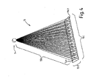
- the space section 15 is defined here by a distance 15h between the 3-D sensor 1 and a surface spanned by a width 15b and a length 151.
- the illuminated by the light source portion 14 has a non-illuminated space 16.
- the subarea is subdivided into a plurality of subarea regions 14.1 to 14.x, which are each delimited discretely here by way of example.
- FIG. 5 is a plan view of the base of an example to be monitored room section 15 shown in the pivoting range of a, for example, driven by a drive movably firing element 17, z. In the form of a door.
- the pivotability of the closing element 17 is schematically symbolized by the arrow 18.
- the 3-D sensor 1 monitors the relevant space section 15.
- a distance 19 between the subareas and / or subareas is defined which is smaller than the smallest extent of a respective specimen. Any objects that are equal to or larger than this distance will cause that in the Reception matrix detected image at least one change in distance between a pixel and the surface of the radiation emitted from the light source radiation.
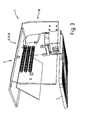
- FIG. 2 shows the 3-D sensor in about the same perspective as the FIG. 1 , but without housing and without beam paths, to make the individual elements more recognizable.
- FIG. 3 again shows the 3-D sensor, also without housing and without beam paths, but from the front and diagonally below.
Landscapes
- Engineering & Computer Science (AREA)
- Physics & Mathematics (AREA)
- Computer Networks & Wireless Communication (AREA)
- General Physics & Mathematics (AREA)
- Radar, Positioning & Navigation (AREA)
- Remote Sensing (AREA)
- Electromagnetism (AREA)
- Optical Radar Systems And Details Thereof (AREA)
- Length Measuring Devices By Optical Means (AREA)
- Measurement Of Optical Distance (AREA)
- Burglar Alarm Systems (AREA)
- Geophysics And Detection Of Objects (AREA)
Priority Applications (1)
| Application Number | Priority Date | Filing Date | Title |
|---|---|---|---|
| EP13004164.3A EP2667218B1 (fr) | 2010-11-15 | 2010-11-15 | Capteur 3D à économie d'énergie |
Applications Claiming Priority (2)
| Application Number | Priority Date | Filing Date | Title |
|---|---|---|---|
| EP10014619.0A EP2453252B1 (fr) | 2010-11-15 | 2010-11-15 | Capteur 3D à économie d'énergie |
| EP13004164.3A EP2667218B1 (fr) | 2010-11-15 | 2010-11-15 | Capteur 3D à économie d'énergie |
Related Parent Applications (3)
| Application Number | Title | Priority Date | Filing Date |
|---|---|---|---|
| EP10014619.0 Division | 2010-11-15 | ||
| EP10014619.0A Division EP2453252B1 (fr) | 2010-11-15 | 2010-11-15 | Capteur 3D à économie d'énergie |
| EP10014619.0A Division-Into EP2453252B1 (fr) | 2010-11-15 | 2010-11-15 | Capteur 3D à économie d'énergie |
Publications (3)
| Publication Number | Publication Date |
|---|---|
| EP2667218A2 true EP2667218A2 (fr) | 2013-11-27 |
| EP2667218A3 EP2667218A3 (fr) | 2013-12-04 |
| EP2667218B1 EP2667218B1 (fr) | 2017-10-18 |
Family
ID=43735089
Family Applications (2)
| Application Number | Title | Priority Date | Filing Date |
|---|---|---|---|
| EP13004164.3A Active EP2667218B1 (fr) | 2010-11-15 | 2010-11-15 | Capteur 3D à économie d'énergie |
| EP10014619.0A Active EP2453252B1 (fr) | 2010-11-15 | 2010-11-15 | Capteur 3D à économie d'énergie |
Family Applications After (1)
| Application Number | Title | Priority Date | Filing Date |
|---|---|---|---|
| EP10014619.0A Active EP2453252B1 (fr) | 2010-11-15 | 2010-11-15 | Capteur 3D à économie d'énergie |
Country Status (3)
| Country | Link |
|---|---|
| US (1) | US8717546B2 (fr) |
| EP (2) | EP2667218B1 (fr) |
| CN (1) | CN102590820A (fr) |
Families Citing this family (16)
| Publication number | Priority date | Publication date | Assignee | Title |
|---|---|---|---|---|
| US8378661B1 (en) * | 2008-05-29 | 2013-02-19 | Alpha-Omega Power Technologies, Ltd.Co. | Solar simulator |
| US20160171297A1 (en) * | 2013-06-25 | 2016-06-16 | Thomson Licensing | Method and device for character input |
| US9674415B2 (en) | 2014-12-22 | 2017-06-06 | Google Inc. | Time-of-flight camera system with scanning illuminator |
| US9635231B2 (en) | 2014-12-22 | 2017-04-25 | Google Inc. | Time-of-flight camera system and method to improve measurement quality of weak field-of-view signal regions |
| EP3156824A1 (fr) | 2015-10-12 | 2017-04-19 | Cedes AG | Capteur de distance tof dote de triple (3) plaque |
| EP3519861A4 (fr) | 2016-10-03 | 2020-09-02 | Sensotech, Inc. | Système de détection basé sur le temps de vol (tof) pour une porte automatique |
| DE102017129641A1 (de) | 2017-12-12 | 2019-06-13 | Bircher Reglomat Ag | 3D Sensorsystem mit einer Freiformoptik |
| DE102017129654A1 (de) | 2017-12-12 | 2019-07-25 | Bircher Reglomat Ag | 3D Szenenerfassung basierend auf Lichtlaufzeiten und einem charakteristischen Merkmal von erfassten elektromagnetischen Wellen |
| DE102017129639A1 (de) | 2017-12-12 | 2019-06-13 | Bircher Reglomat Ag | 3D Sensorsystem mit einer von einem Raumwinkel abhängigen Szenenbeleuchtung |
| DE102017129663A1 (de) | 2017-12-12 | 2019-06-13 | Bircher Reglomat Ag | Sensorsystem mit einer Lichtfeldkamera zum Bestimmen der Charakteristik einer Szene |
| DE102017129626A1 (de) | 2017-12-12 | 2019-06-13 | Bircher Reglomat Ag | Sensorsystem zum dreidimensionalen Erfassen einer Szene mit verschiedenen Photonenakkumulationen |
| EP3527766B1 (fr) | 2018-02-16 | 2023-03-29 | Cedes AG | Procédé de configurationd'un capteur de porte |
| EP3527954B1 (fr) | 2018-02-16 | 2022-03-30 | Cedes AG | Capteur de porte à détecteur d'angle de rotation |
| DE102019112338A1 (de) | 2019-05-10 | 2020-11-12 | Bircher Reglomat Ag | 3D Sensorsystem, betreibbar in verschiedenen Betriebsmodi in Abhängigkeit eines Betriebszustandes eines Verschließkörpers |
| DE102019112340A1 (de) | 2019-05-10 | 2020-11-12 | Bircher Reglomat Ag | TOF Sensorsystem mit einer Beleuchtungseinrichtung mit einem Array von Einzellichtquellen |
| DE102019112339A1 (de) | 2019-05-10 | 2020-11-12 | Bircher Reglomat Ag | Identifizierung eines Objekts basierend auf einer Erkennung eines Teils des Objekts und auf Beschreibungsdaten von einem Referenzobjekt |
Family Cites Families (8)
| Publication number | Priority date | Publication date | Assignee | Title |
|---|---|---|---|---|
| EP1031471B1 (fr) * | 1999-02-25 | 2004-12-15 | Siemens Aktiengesellschaft | Procédé ou appareil pour la création d'un image de position utilisant la rayonnement que est réfléchie ou émis par un objet ou une personne |
| US6584283B2 (en) * | 2001-02-02 | 2003-06-24 | Eastman Kodak Company | LED illumination device for a scannerless range imaging system |
| JP4228132B2 (ja) * | 2002-10-18 | 2009-02-25 | 株式会社トプコン | 位置測定装置 |
| GB2395261A (en) * | 2002-11-11 | 2004-05-19 | Qinetiq Ltd | Ranging apparatus |
| JP2008107583A (ja) * | 2006-10-26 | 2008-05-08 | Sony Corp | 3次元画像表示装置及びその表示方法 |
| ATE552514T1 (de) * | 2006-12-02 | 2012-04-15 | Sick Ag | Optoelektronischer mehrebenensensor und verfahren zur erfassung von objekten |
| DE102007031157A1 (de) * | 2006-12-15 | 2008-06-26 | Sick Ag | Optoelektronischer Sensor sowie Verfahren zur Erfassung und Abstandsbestimmung eines Objekts |
| KR101467509B1 (ko) * | 2008-07-25 | 2014-12-01 | 삼성전자주식회사 | 이미지 센서 및 이미지 센서 동작 방법 |
-
2010
- 2010-11-15 EP EP13004164.3A patent/EP2667218B1/fr active Active
- 2010-11-15 EP EP10014619.0A patent/EP2453252B1/fr active Active
-
2011
- 2011-11-14 US US13/295,573 patent/US8717546B2/en active Active
- 2011-11-15 CN CN2011104625361A patent/CN102590820A/zh active Pending
Non-Patent Citations (1)
| Title |
|---|
| None |
Also Published As
| Publication number | Publication date |
|---|---|
| EP2667218B1 (fr) | 2017-10-18 |
| US20120119062A1 (en) | 2012-05-17 |
| EP2453252B1 (fr) | 2015-06-10 |
| EP2453252A1 (fr) | 2012-05-16 |
| CN102590820A (zh) | 2012-07-18 |
| US8717546B2 (en) | 2014-05-06 |
| EP2667218A3 (fr) | 2013-12-04 |
Similar Documents
| Publication | Publication Date | Title |
|---|---|---|
| EP2453252B1 (fr) | Capteur 3D à économie d'énergie | |
| EP3729137B1 (fr) | Système lidar à impulsions multiples pour la détection multidimensionnelle d'objets | |
| EP2112039B1 (fr) | Dispositif de capteur optique | |
| DE102007014034B3 (de) | Optischer Sensorchip und Einklemmschutzvorrichtung mit einem solchen | |
| DE3627972C2 (fr) | ||
| DE102021000724B3 (de) | Mikrolinsenarray-Projektionsvorrichtung, Beleuchtungsvorrichtung und Fahrzeug | |
| EP0188748A1 (fr) | Dispositif d'alarme détecteur d'intrus | |
| EP1794619B1 (fr) | Dispositif de surveillance optique de zones tridimensionnelles | |
| DE102004011780A1 (de) | Zugangskontrolleinrichtung | |
| EP1916545B1 (fr) | Capteur optoélectronique et son procédé de fonctionnement | |
| EP1065521B1 (fr) | Système de surveillance optoélectronique | |
| DE102007043378B4 (de) | Lichtgitter | |
| WO2019110206A1 (fr) | Système lidar de perception de l'environnement et procédé pour faire fonctionner un système lidar | |
| DE10001017B4 (de) | Optoelektronischer Sensor, insbesondere Reflexlichttaster | |
| EP4001854A1 (fr) | Capteur | |
| EP2851704B1 (fr) | Dispositif et procédé de détermination optique de distances par rapport à des objets dans une zone de surveillance | |
| DE102017101791A1 (de) | Optoelektronische Sensoreinrichtung für ein Kraftfahrzeug und Kraftfahrzeug | |
| EP2065732A2 (fr) | Capteur optique et procédé de détermination de la position d'objets | |
| EP2916143A1 (fr) | Dispositif et procédé de détection d'objets dans une zone de surveillance | |
| DE102012100746B4 (de) | Sendeeinheit für einen optischen Sensor | |
| EP1811427A1 (fr) | Procédé et dispositif pour la surveillance d'un domaine | |
| WO2020229189A1 (fr) | Système de détection tof doté d'un dispositif d'éclairage comprenant un réseau de sources lumineuses individuelles | |
| DE1524368B2 (de) | Vorrichtung zum Abtasten von Loch streifen | |
| EP1686398B1 (fr) | Capteur optoélectronique | |
| EP2034352A2 (fr) | Système de projection laser doté d'un contrôle de puissance |
Legal Events
| Date | Code | Title | Description |
|---|---|---|---|
| PUAL | Search report despatched |
Free format text: ORIGINAL CODE: 0009013 |
|
| PUAI | Public reference made under article 153(3) epc to a published international application that has entered the european phase |
Free format text: ORIGINAL CODE: 0009012 |
|
| AC | Divisional application: reference to earlier application |
Ref document number: 2453252 Country of ref document: EP Kind code of ref document: P |
|
| AK | Designated contracting states |
Kind code of ref document: A2 Designated state(s): AL AT BE BG CH CY CZ DE DK EE ES FI FR GB GR HR HU IE IS IT LI LT LU LV MC MK MT NL NO PL PT RO RS SE SI SK SM TR |
|
| AK | Designated contracting states |
Kind code of ref document: A3 Designated state(s): AL AT BE BG CH CY CZ DE DK EE ES FI FR GB GR HR HU IE IS IT LI LT LU LV MC MK MT NL NO PL PT RO RS SE SI SK SM TR |
|
| RIC1 | Information provided on ipc code assigned before grant |
Ipc: G01S 7/481 20060101AFI20131028BHEP Ipc: G01S 17/89 20060101ALI20131028BHEP Ipc: G01S 17/02 20060101ALI20131028BHEP Ipc: G01S 17/87 20060101ALI20131028BHEP Ipc: G01S 7/497 20060101ALI20131028BHEP |
|
| 17P | Request for examination filed |
Effective date: 20140530 |
|
| RBV | Designated contracting states (corrected) |
Designated state(s): AL AT BE BG CH CY CZ DE DK EE ES FI FR GB GR HR HU IE IS IT LI LT LU LV MC MK MT NL NO PL PT RO RS SE SI SK SM TR |
|
| GRAP | Despatch of communication of intention to grant a patent |
Free format text: ORIGINAL CODE: EPIDOSNIGR1 |
|
| STAA | Information on the status of an ep patent application or granted ep patent |
Free format text: STATUS: GRANT OF PATENT IS INTENDED |
|
| GRAJ | Information related to disapproval of communication of intention to grant by the applicant or resumption of examination proceedings by the epo deleted |
Free format text: ORIGINAL CODE: EPIDOSDIGR1 |
|
| STAA | Information on the status of an ep patent application or granted ep patent |
Free format text: STATUS: REQUEST FOR EXAMINATION WAS MADE |
|
| INTG | Intention to grant announced |
Effective date: 20170320 |
|
| INTC | Intention to grant announced (deleted) | ||
| GRAP | Despatch of communication of intention to grant a patent |
Free format text: ORIGINAL CODE: EPIDOSNIGR1 |
|
| STAA | Information on the status of an ep patent application or granted ep patent |
Free format text: STATUS: GRANT OF PATENT IS INTENDED |
|
| INTG | Intention to grant announced |
Effective date: 20170516 |
|
| GRAS | Grant fee paid |
Free format text: ORIGINAL CODE: EPIDOSNIGR3 |
|
| GRAA | (expected) grant |
Free format text: ORIGINAL CODE: 0009210 |
|
| STAA | Information on the status of an ep patent application or granted ep patent |
Free format text: STATUS: THE PATENT HAS BEEN GRANTED |
|
| AC | Divisional application: reference to earlier application |
Ref document number: 2453252 Country of ref document: EP Kind code of ref document: P |
|
| AK | Designated contracting states |
Kind code of ref document: B1 Designated state(s): AL AT BE BG CH CY CZ DE DK EE ES FI FR GB GR HR HU IE IS IT LI LT LU LV MC MK MT NL NO PL PT RO RS SE SI SK SM TR |
|
| REG | Reference to a national code |
Ref country code: GB Ref legal event code: FG4D Free format text: NOT ENGLISH |
|
| REG | Reference to a national code |
Ref country code: CH Ref legal event code: EP |
|
| REG | Reference to a national code |
Ref country code: AT Ref legal event code: REF Ref document number: 938426 Country of ref document: AT Kind code of ref document: T Effective date: 20171115 Ref country code: IE Ref legal event code: FG4D Free format text: LANGUAGE OF EP DOCUMENT: GERMAN |
|
| REG | Reference to a national code |
Ref country code: DE Ref legal event code: R096 Ref document number: 502010014288 Country of ref document: DE |
|
| REG | Reference to a national code |
Ref country code: NL Ref legal event code: MP Effective date: 20171018 |
|
| REG | Reference to a national code |
Ref country code: LT Ref legal event code: MG4D |
|
| PG25 | Lapsed in a contracting state [announced via postgrant information from national office to epo] |
Ref country code: NL Free format text: LAPSE BECAUSE OF FAILURE TO SUBMIT A TRANSLATION OF THE DESCRIPTION OR TO PAY THE FEE WITHIN THE PRESCRIBED TIME-LIMIT Effective date: 20171018 |
|
| PG25 | Lapsed in a contracting state [announced via postgrant information from national office to epo] |
Ref country code: SE Free format text: LAPSE BECAUSE OF FAILURE TO SUBMIT A TRANSLATION OF THE DESCRIPTION OR TO PAY THE FEE WITHIN THE PRESCRIBED TIME-LIMIT Effective date: 20171018 Ref country code: NO Free format text: LAPSE BECAUSE OF FAILURE TO SUBMIT A TRANSLATION OF THE DESCRIPTION OR TO PAY THE FEE WITHIN THE PRESCRIBED TIME-LIMIT Effective date: 20180118 Ref country code: LT Free format text: LAPSE BECAUSE OF FAILURE TO SUBMIT A TRANSLATION OF THE DESCRIPTION OR TO PAY THE FEE WITHIN THE PRESCRIBED TIME-LIMIT Effective date: 20171018 Ref country code: ES Free format text: LAPSE BECAUSE OF FAILURE TO SUBMIT A TRANSLATION OF THE DESCRIPTION OR TO PAY THE FEE WITHIN THE PRESCRIBED TIME-LIMIT Effective date: 20171018 |
|
| PG25 | Lapsed in a contracting state [announced via postgrant information from national office to epo] |
Ref country code: GR Free format text: LAPSE BECAUSE OF FAILURE TO SUBMIT A TRANSLATION OF THE DESCRIPTION OR TO PAY THE FEE WITHIN THE PRESCRIBED TIME-LIMIT Effective date: 20180119 Ref country code: RS Free format text: LAPSE BECAUSE OF FAILURE TO SUBMIT A TRANSLATION OF THE DESCRIPTION OR TO PAY THE FEE WITHIN THE PRESCRIBED TIME-LIMIT Effective date: 20171018 Ref country code: LV Free format text: LAPSE BECAUSE OF FAILURE TO SUBMIT A TRANSLATION OF THE DESCRIPTION OR TO PAY THE FEE WITHIN THE PRESCRIBED TIME-LIMIT Effective date: 20171018 Ref country code: BG Free format text: LAPSE BECAUSE OF FAILURE TO SUBMIT A TRANSLATION OF THE DESCRIPTION OR TO PAY THE FEE WITHIN THE PRESCRIBED TIME-LIMIT Effective date: 20180118 Ref country code: IS Free format text: LAPSE BECAUSE OF FAILURE TO SUBMIT A TRANSLATION OF THE DESCRIPTION OR TO PAY THE FEE WITHIN THE PRESCRIBED TIME-LIMIT Effective date: 20180218 Ref country code: HR Free format text: LAPSE BECAUSE OF FAILURE TO SUBMIT A TRANSLATION OF THE DESCRIPTION OR TO PAY THE FEE WITHIN THE PRESCRIBED TIME-LIMIT Effective date: 20171018 |
|
| REG | Reference to a national code |
Ref country code: DE Ref legal event code: R097 Ref document number: 502010014288 Country of ref document: DE |
|
| PG25 | Lapsed in a contracting state [announced via postgrant information from national office to epo] |
Ref country code: MC Free format text: LAPSE BECAUSE OF FAILURE TO SUBMIT A TRANSLATION OF THE DESCRIPTION OR TO PAY THE FEE WITHIN THE PRESCRIBED TIME-LIMIT Effective date: 20171018 Ref country code: CZ Free format text: LAPSE BECAUSE OF FAILURE TO SUBMIT A TRANSLATION OF THE DESCRIPTION OR TO PAY THE FEE WITHIN THE PRESCRIBED TIME-LIMIT Effective date: 20171018 Ref country code: EE Free format text: LAPSE BECAUSE OF FAILURE TO SUBMIT A TRANSLATION OF THE DESCRIPTION OR TO PAY THE FEE WITHIN THE PRESCRIBED TIME-LIMIT Effective date: 20171018 Ref country code: SK Free format text: LAPSE BECAUSE OF FAILURE TO SUBMIT A TRANSLATION OF THE DESCRIPTION OR TO PAY THE FEE WITHIN THE PRESCRIBED TIME-LIMIT Effective date: 20171018 Ref country code: DK Free format text: LAPSE BECAUSE OF FAILURE TO SUBMIT A TRANSLATION OF THE DESCRIPTION OR TO PAY THE FEE WITHIN THE PRESCRIBED TIME-LIMIT Effective date: 20171018 |
|
| PLBE | No opposition filed within time limit |
Free format text: ORIGINAL CODE: 0009261 |
|
| STAA | Information on the status of an ep patent application or granted ep patent |
Free format text: STATUS: NO OPPOSITION FILED WITHIN TIME LIMIT |
|
| PG25 | Lapsed in a contracting state [announced via postgrant information from national office to epo] |
Ref country code: RO Free format text: LAPSE BECAUSE OF FAILURE TO SUBMIT A TRANSLATION OF THE DESCRIPTION OR TO PAY THE FEE WITHIN THE PRESCRIBED TIME-LIMIT Effective date: 20171018 Ref country code: PL Free format text: LAPSE BECAUSE OF FAILURE TO SUBMIT A TRANSLATION OF THE DESCRIPTION OR TO PAY THE FEE WITHIN THE PRESCRIBED TIME-LIMIT Effective date: 20171018 Ref country code: LU Free format text: LAPSE BECAUSE OF NON-PAYMENT OF DUE FEES Effective date: 20171115 Ref country code: SM Free format text: LAPSE BECAUSE OF FAILURE TO SUBMIT A TRANSLATION OF THE DESCRIPTION OR TO PAY THE FEE WITHIN THE PRESCRIBED TIME-LIMIT Effective date: 20171018 |
|
| REG | Reference to a national code |
Ref country code: FR Ref legal event code: ST Effective date: 20180731 |
|
| REG | Reference to a national code |
Ref country code: IE Ref legal event code: MM4A |
|
| 26N | No opposition filed |
Effective date: 20180719 |
|
| GBPC | Gb: european patent ceased through non-payment of renewal fee |
Effective date: 20180118 |
|
| PG25 | Lapsed in a contracting state [announced via postgrant information from national office to epo] |
Ref country code: MT Free format text: LAPSE BECAUSE OF FAILURE TO SUBMIT A TRANSLATION OF THE DESCRIPTION OR TO PAY THE FEE WITHIN THE PRESCRIBED TIME-LIMIT Effective date: 20171018 |
|
| PG25 | Lapsed in a contracting state [announced via postgrant information from national office to epo] |
Ref country code: IE Free format text: LAPSE BECAUSE OF NON-PAYMENT OF DUE FEES Effective date: 20171115 Ref country code: FR Free format text: LAPSE BECAUSE OF NON-PAYMENT OF DUE FEES Effective date: 20171218 |
|
| PG25 | Lapsed in a contracting state [announced via postgrant information from national office to epo] |
Ref country code: SI Free format text: LAPSE BECAUSE OF FAILURE TO SUBMIT A TRANSLATION OF THE DESCRIPTION OR TO PAY THE FEE WITHIN THE PRESCRIBED TIME-LIMIT Effective date: 20171018 Ref country code: GB Free format text: LAPSE BECAUSE OF NON-PAYMENT OF DUE FEES Effective date: 20180118 |
|
| REG | Reference to a national code |
Ref country code: AT Ref legal event code: MM01 Ref document number: 938426 Country of ref document: AT Kind code of ref document: T Effective date: 20171115 |
|
| PG25 | Lapsed in a contracting state [announced via postgrant information from national office to epo] |
Ref country code: AT Free format text: LAPSE BECAUSE OF NON-PAYMENT OF DUE FEES Effective date: 20171115 |
|
| PG25 | Lapsed in a contracting state [announced via postgrant information from national office to epo] |
Ref country code: HU Free format text: LAPSE BECAUSE OF FAILURE TO SUBMIT A TRANSLATION OF THE DESCRIPTION OR TO PAY THE FEE WITHIN THE PRESCRIBED TIME-LIMIT; INVALID AB INITIO Effective date: 20101115 |
|
| PG25 | Lapsed in a contracting state [announced via postgrant information from national office to epo] |
Ref country code: CY Free format text: LAPSE BECAUSE OF NON-PAYMENT OF DUE FEES Effective date: 20171018 |
|
| PG25 | Lapsed in a contracting state [announced via postgrant information from national office to epo] |
Ref country code: MK Free format text: LAPSE BECAUSE OF FAILURE TO SUBMIT A TRANSLATION OF THE DESCRIPTION OR TO PAY THE FEE WITHIN THE PRESCRIBED TIME-LIMIT Effective date: 20171018 |
|
| PG25 | Lapsed in a contracting state [announced via postgrant information from national office to epo] |
Ref country code: TR Free format text: LAPSE BECAUSE OF FAILURE TO SUBMIT A TRANSLATION OF THE DESCRIPTION OR TO PAY THE FEE WITHIN THE PRESCRIBED TIME-LIMIT Effective date: 20171018 |
|
| PG25 | Lapsed in a contracting state [announced via postgrant information from national office to epo] |
Ref country code: PT Free format text: LAPSE BECAUSE OF FAILURE TO SUBMIT A TRANSLATION OF THE DESCRIPTION OR TO PAY THE FEE WITHIN THE PRESCRIBED TIME-LIMIT Effective date: 20171018 |
|
| PG25 | Lapsed in a contracting state [announced via postgrant information from national office to epo] |
Ref country code: AL Free format text: LAPSE BECAUSE OF FAILURE TO SUBMIT A TRANSLATION OF THE DESCRIPTION OR TO PAY THE FEE WITHIN THE PRESCRIBED TIME-LIMIT Effective date: 20171018 |
|
| PGFP | Annual fee paid to national office [announced via postgrant information from national office to epo] |
Ref country code: IT Payment date: 20221130 Year of fee payment: 13 Ref country code: FI Payment date: 20221117 Year of fee payment: 13 |
|
| PGFP | Annual fee paid to national office [announced via postgrant information from national office to epo] |
Ref country code: CH Payment date: 20221124 Year of fee payment: 13 |
|
| P01 | Opt-out of the competence of the unified patent court (upc) registered |
Effective date: 20230519 |
|
| REG | Reference to a national code |
Ref country code: CH Ref legal event code: PL |
|
| PG25 | Lapsed in a contracting state [announced via postgrant information from national office to epo] |
Ref country code: CH Free format text: LAPSE BECAUSE OF NON-PAYMENT OF DUE FEES Effective date: 20231130 |
|
| PG25 | Lapsed in a contracting state [announced via postgrant information from national office to epo] |
Ref country code: FI Free format text: LAPSE BECAUSE OF NON-PAYMENT OF DUE FEES Effective date: 20231115 Ref country code: CH Free format text: LAPSE BECAUSE OF NON-PAYMENT OF DUE FEES Effective date: 20231130 |
|
| PG25 | Lapsed in a contracting state [announced via postgrant information from national office to epo] |
Ref country code: IT Free format text: LAPSE BECAUSE OF NON-PAYMENT OF DUE FEES Effective date: 20231115 |
|
| PG25 | Lapsed in a contracting state [announced via postgrant information from national office to epo] |
Ref country code: IT Free format text: LAPSE BECAUSE OF NON-PAYMENT OF DUE FEES Effective date: 20231115 |
|
| REG | Reference to a national code |
Ref country code: DE Ref legal event code: R082 Ref document number: 502010014288 Country of ref document: DE Representative=s name: RAVENSPAT PATENTANWAELTE PARTNERSCHAFT MBB, DE |
|
| PGFP | Annual fee paid to national office [announced via postgrant information from national office to epo] |
Ref country code: DE Payment date: 20251118 Year of fee payment: 16 |
|
| PGFP | Annual fee paid to national office [announced via postgrant information from national office to epo] |
Ref country code: BE Payment date: 20251118 Year of fee payment: 16 |