EP1496577A2 - Elektrische Anschluss- und Verbindungsdose - Google Patents
Elektrische Anschluss- und Verbindungsdose Download PDFInfo
- Publication number
- EP1496577A2 EP1496577A2 EP04012404A EP04012404A EP1496577A2 EP 1496577 A2 EP1496577 A2 EP 1496577A2 EP 04012404 A EP04012404 A EP 04012404A EP 04012404 A EP04012404 A EP 04012404A EP 1496577 A2 EP1496577 A2 EP 1496577A2
- Authority
- EP
- European Patent Office
- Prior art keywords
- module
- housing
- electrical
- connection
- plug
- Prior art date
- Legal status (The legal status is an assumption and is not a legal conclusion. Google has not performed a legal analysis and makes no representation as to the accuracy of the status listed.)
- Granted
Links
Images

Classifications
-
- H—ELECTRICITY
- H01—ELECTRIC ELEMENTS
- H01R—ELECTRICALLY-CONDUCTIVE CONNECTIONS; STRUCTURAL ASSOCIATIONS OF A PLURALITY OF MUTUALLY-INSULATED ELECTRICAL CONNECTING ELEMENTS; COUPLING DEVICES; CURRENT COLLECTORS
- H01R13/00—Details of coupling devices of the kinds covered by groups H01R12/70 or H01R24/00 - H01R33/00
- H01R13/66—Structural association with built-in electrical component
- H01R13/6608—Structural association with built-in electrical component with built-in single component
- H01R13/6641—Structural association with built-in electrical component with built-in single component with diode
-
- H—ELECTRICITY
- H02—GENERATION; CONVERSION OR DISTRIBUTION OF ELECTRIC POWER
- H02S—GENERATION OF ELECTRIC POWER BY CONVERSION OF INFRARED RADIATION, VISIBLE LIGHT OR ULTRAVIOLET LIGHT, e.g. USING PHOTOVOLTAIC [PV] MODULES
- H02S40/00—Components or accessories in combination with PV modules, not provided for in groups H02S10/00 - H02S30/00
- H02S40/30—Electrical components
- H02S40/34—Electrical components comprising specially adapted electrical connection means to be structurally associated with the PV module, e.g. junction boxes
-
- Y—GENERAL TAGGING OF NEW TECHNOLOGICAL DEVELOPMENTS; GENERAL TAGGING OF CROSS-SECTIONAL TECHNOLOGIES SPANNING OVER SEVERAL SECTIONS OF THE IPC; TECHNICAL SUBJECTS COVERED BY FORMER USPC CROSS-REFERENCE ART COLLECTIONS [XRACs] AND DIGESTS
- Y02—TECHNOLOGIES OR APPLICATIONS FOR MITIGATION OR ADAPTATION AGAINST CLIMATE CHANGE
- Y02E—REDUCTION OF GREENHOUSE GAS [GHG] EMISSIONS, RELATED TO ENERGY GENERATION, TRANSMISSION OR DISTRIBUTION
- Y02E10/00—Energy generation through renewable energy sources
- Y02E10/50—Photovoltaic [PV] energy
Definitions
- the invention relates to an electrical connection and junction box, with a housing, inserted for connection and connection in the housing Lines with each other or provided in the housing electrical or / and electronic devices.
- Such electrical connection and junction boxes are from the prior Technology known in a variety of configurations and are in the most diverse Application areas used. Among other things, such electrical Connection and connection boxes also for connecting solar cells used.
- bypass diodes To the problems associated with partially shaded solar cells to avoid, often diodes, called bypass diodes, are used be switched anti-parallel to the solar cells. In this way it is achieved that a shaded solar cell, although no longer a part of the total voltage of the solar cell module, but still receive the flow of current remains. The solar cell module thus shows only a reduced Operating voltage, but not completely off. In addition, in the shaded solar cell no longer implemented power, so that damage the shaded solar cell can be avoided.
- every solar cell of a solar cell module could have exactly one Be associated diode.
- a plurality connected in series by a common solar cell Diode is protected.
- one of the housing of the electrical connection and Junction box various plug-in module provided that electrical Devices, such as diodes, may have.
- electrical Devices such as diodes
- the clip-on module so z. B. of bypass diodes for solar cells one Solar cell module, the housing of the electrical connection and junction box no longer needs to be opened.
- the plug-in module, the one defective electrical and / or electronic device, ie z. B. has a defective bypass diode, simply pulled off and replaced by a new one Receptacle module can be replaced, which simply plugged back into the housing can be.
- the plug-in module by means of the connector directly with be connected to the housing, wherein as a connector z. B. on the Housing the electrical connection and junction box provided Plug and a cooperating with this connector socket on the plug-in module can be provided.
- an adapter is provided between the housing and the Plug-in module. It is valid for both direct attachment of the clip-on module to the housing of the electrical connection and junction box as well as for plugging the clip-on module via an adapter plug provided between the plug-in module and the housing, that between housing and pinch module or housing, adapter plug and plug-in module preferably no further lines provided are, housing and plug-in module or housing, adapter plug and plug-in module so directly connected and plugged together are.
- Adapter plugs have several advantages:
- the insectstekker having a Meß effetsanschluß for connecting a measuring line.
- a measuring or display device also removed from the electrical Connection and junction box are arranged so that to check the connected by means of the electrical connection and connection box or connected electrical equipment not directly to the electrical Connection and connection box must be measured.
- Firmly connected Leads for checking or monitoring the over the electrical Connection and connection box connected or connected electrical and / or electronic devices has such an adapter plug a higher flexibility, in particular, the adapter plug namely, without further notice of the electrical connection and Junction box be removed so that it is not there in normal operation continues to bother.
- the electrical and / or electronic devices in the plug-in module free, z. B. on a board, be arranged.
- the electrical and / or electronic devices in the plug-in module in a casting agent are poured.
- a shedding comes in Kunststoffharzstoff into consideration, as well as other areas in electrical Circuits known.
- Adjacent casting can be in the electrical and / or electronic Facilities resulting heat are better dissipated by these than if the electrical and / or electronic devices only with the ambient air present in the plug-in module would be in contact.
- the encapsulant protects the electrical and / or electronic Devices against external influences, in particular namely mechanical Strains or the effect of moisture and moisture.
- the electrical connection according to the invention and junction box according to a preferred embodiment of the invention especially for connecting solar cells of a solar cell module suitable.
- the electrical connection and junction box is secured by means of the housing to the solar cell module or a roof.
- the plug-in module tool-free of the housing is solvable.
- the clip-on module preferably has a Has a plurality of bypass diodes for the solar cell of the solar cell module. This is a simple change of the plug-in module to replace defective Bypass diodes, without the housing of the electrical connection and to open the junction box and without a tool use.
- bypass diodes in the clip module are according to a preferred one Development of the invention, as already indicated above, in a Pouring compound poured, so beyond that in the bypass diodes converted power, which leads to a heating of the bypass diodes, good discharged to the outside.
- FIG. 1 is an electrical connection and junction box according to a preferred embodiment of the invention in a perspective view can be seen, which has a housing 1 and a pin 2.
- a so-called solar can so a can for connecting and connecting several solar cells of a solar cell module, including with bypass diodes.
- connection options typically not in shape further illustrated terminals, provided.
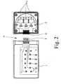
- FIG. 2 One with the typically in the form of terminals present connection options achievable interconnection is exemplified in FIG. 2 can be seen.
- the plug-in module 2 as also shown in FIG. 2, diodes 3, which as bypass diodes to serve for solar cells of a solar cell module.
- connection module 3 is connected to the housing 1 by means of a plug connection 4 plugged.
- the connector 4 consists of a provided on the housing 1 Plug 5 and a connector 5 corresponding to this socket 6 am Connection module 2.
- This connector 4 are those line connections out of the housing 1 in the connection module 2, the must be connected to the diodes 3, as shown in detail in FIG.
- the connector 4 with connector 5 and 6 socket is designed such that the connection module 2 is simply plugged onto the housing 1 without a To use tool.
- plugs 5 and Socket 6 of the connector 4 are readily formed such that the achieved connection between the housing 1 and the connection module. 2 is so stable that no further means for fastening and holding of the connection module 2 on the housing 1 must be provided.
- intermediate connector can be provided between the housing 1 and the connection module 2 can not continue illustrated intermediate connector.
- Such an intermediary is typically designed so that it is on the side of the housing 1 is provided with a socket, which is the socket 6 of the connection module 2, and on its side facing the connection module 2 side with a Plug is provided, which corresponds to the plug 5 of the housing 1.
- the adapter plug simultaneously or alternatively a diagnostic connection for an external measuring device and a measuring line connection for connection a measuring line. This can be easily different Verification process, among other things, namely Check if the diodes 3 are still fully functional and if the individual Solar cells or rows of solar cells work properly.
- the diodes 3 in the connection module 2 in a Grouts are poured, in such a way that this casting agent directly is applied to the diodes 3 and also complete contact with the inner walls of the connection module 2 has. With the help of this casting agent is achieved that the resulting heat in the diodes 3 effectively outward can be dissipated to the environment of the connection module 2.
Landscapes
- Photovoltaic Devices (AREA)
- Details Of Connecting Devices For Male And Female Coupling (AREA)
- Coupling Device And Connection With Printed Circuit (AREA)
Abstract
Description
- Fig. 1
- eine elektrische Anschluß- und Verbindungsdose gemäß einem bevorzugten Ausführungsbeispiel der Erfindung in perspektivischer Ansicht und
- Fig. 2
- die elektrische Anschluß- und Verbindungsdose gemäß dem bevorzugten Ausführungsbeispiel der Erfindung mit ihrer elektrischen Verschaltung.
Claims (9)
- Elektrische Anschluß- und Verbindungsdose, mit einem Gehäuse (1), zum Anschließen und Verbinden in das Gehäuse (1) eingeführter Leitungen miteinander bzw. mit in dem Gehäuse (1) vorgesehenen elektrischen oder/und elektronischen Einrichtungen, dadurch gekennzeichnet, daß ein elektrische oder/und elektronische Einrichtungen aufweisendes Ansteckmodul (2) vorgesehen ist, das mittels einer Steckverbindung (4) an das Gehäuse (1) angesteckt ist, so daß die elektrischen oder/und elektronischen Einrichtungen des Ansteckmoduls (2) mit den in dem Gehäuse (1) vorgesehenen Leitungen bzw. elektrischen oder/und elektronischen Einrichtungen verbunden sind.
- Elektrische Anschluß- und Verbindungsdose nach Anspruch 1, dadurch gekennzeichnet, daß zwischen dem Gehäuse (1) und dem Ansteckmodul (2) ein Zwischenstecker vorgesehen ist.
- Elektrische Anschluß- und Verbindungsdose nach Anspruch 2, dadurch gekennzeichnet, daß der Zwischenstecker einen Diagnoseanschluß für ein externes Meßgerät oder/und einen Meßleitungsanschluß zum Anschließen einer Meßleitung aufweist.
- Elektrische Anschluß- und Verbindungsdose nach einem der Ansprüche 1 bis 3, dadurch gekennzeichnet, daß die elektrischen oder/und elektronischen Einrichtungen in dem Ansteckmodul (2) in ein Vergußmittel eingegossen sind.
- Elektrische Anschluß- und Verbindungsdose nach einem der Ansprüche 1 bis 4, dadurch gekennzeichnet, daß das Ansteckmodul (2) eine Mehrzahl von Dioden (3) aufweist.
- Verwendung einer elektrischen Anschluß- und Verbindungsdose nach einem der Ansprüche 1 bis 5 zum Anschluß von Solarzellen eines Solarzellenmoduls.
- Verwendung nach Anspruch 6, dadurch gekennzeichnet, daß die elektrische Anschluß- und Verbindungsdose mittels des Gehäuses (1) an dem Solarzellenmodul oder einem Dach befestigt ist und vorzugsweise das Ansteckmodul (2) werkzeugfrei von dem Gehäuse (1) lösbar ist.
- Verwendung nach Anspruch 6 oder 7, dadurch gekennzeichnet, daß das Ansteckmodul (2) eine Mehrzahl von Bypass-Dioden (3) aufweist.
- Verwendung nach Anspruch 8, dadurch gekennzeichnet, daß die Bypass-Dioden (3) in ein Vergußmittel eingegossen sind.
Applications Claiming Priority (2)
| Application Number | Priority Date | Filing Date | Title |
|---|---|---|---|
| DE10331780A DE10331780B4 (de) | 2003-07-11 | 2003-07-11 | Elektrische Anschluß- und Verbindungsdose |
| DE10331780 | 2003-07-11 |
Publications (3)
| Publication Number | Publication Date |
|---|---|
| EP1496577A2 true EP1496577A2 (de) | 2005-01-12 |
| EP1496577A3 EP1496577A3 (de) | 2005-10-05 |
| EP1496577B1 EP1496577B1 (de) | 2007-07-25 |
Family
ID=33441750
Family Applications (1)
| Application Number | Title | Priority Date | Filing Date |
|---|---|---|---|
| EP04012404A Expired - Lifetime EP1496577B1 (de) | 2003-07-11 | 2004-05-26 | Elektrische Anschluss- und Verbindungsdose |
Country Status (4)
| Country | Link |
|---|---|
| EP (1) | EP1496577B1 (de) |
| AT (1) | ATE368314T1 (de) |
| DE (2) | DE10331780B4 (de) |
| ES (1) | ES2290588T3 (de) |
Cited By (10)
| Publication number | Priority date | Publication date | Assignee | Title |
|---|---|---|---|---|
| DE102004053942A1 (de) * | 2004-11-09 | 2006-05-11 | Solarwatt Solar-Systeme Gmbh | Anschlusseinheit für photovoltaische Solarmodule |
| DE102007037797A1 (de) * | 2007-08-10 | 2009-02-26 | Tyco Electronics Amp Gmbh | Elektrisches Anschlusssystem für photovoltaische Solaranlagen |
| US7898114B2 (en) | 2005-05-24 | 2011-03-01 | Fraunhofer-Gesellschaft Zur Forderung Der Angewandten Forschung E.V. | Protective circuit device for a solar module |
| WO2010054837A3 (de) * | 2008-11-14 | 2011-04-21 | Yamaichi Electronics Deutschland Gmbh | Solarpaneel, verfahren zum herstellen und überbrückungsdose |
| CN102195695A (zh) * | 2010-03-02 | 2011-09-21 | 电信科学技术研究院 | 天线校准的方法及装置 |
| ITMI20110917A1 (it) * | 2011-05-23 | 2012-11-24 | Compel Electronics S P A | Scatola di giunzione per pannelli fotovoltaici |
| US9577119B2 (en) | 2012-06-07 | 2017-02-21 | Hanwha Q.CELLS GmbH | Solar module with a plug-in device |
| EP3213406A1 (de) * | 2014-10-28 | 2017-09-06 | Corner Star Limited | Fotovoltaikmodule mit externen bypass-dioden |
| EP2386125B1 (de) * | 2009-01-08 | 2017-10-18 | Yamaichi Electronics Deutschland GmbH | Solarpaneel und verfahren zu dessen herstellung |
| CN109728487A (zh) * | 2017-10-30 | 2019-05-07 | 泰科电子(上海)有限公司 | 适配器 |
Families Citing this family (8)
| Publication number | Priority date | Publication date | Assignee | Title |
|---|---|---|---|---|
| DE102005012213B4 (de) * | 2005-01-26 | 2009-01-15 | G. Spelsberg Gmbh & Co. Kg | Anschlußschaltung |
| DE102009018360A1 (de) | 2009-04-23 | 2010-11-04 | Rena Gmbh | Verfahren und Vorrichtung zur elektrolytischen Behandlung von Solarzellen |
| US10404208B2 (en) | 2015-06-02 | 2019-09-03 | Ja Solar Usa Inc. | Apparatus and method of a universal module junction box |
| EP3304729B1 (de) * | 2015-06-02 | 2025-03-05 | Ja Solar USA | Vorrichtung eines universalanschlusskastens für module |
| DE102015218526B4 (de) | 2015-09-25 | 2023-05-25 | Hanwha Q Cells Gmbh | Anschlussanordnung für ein Solarmodul |
| CN107174753B (zh) | 2017-05-15 | 2019-09-03 | 中国医学科学院肿瘤医院 | 多机械臂式术中放射治疗装置 |
| CN112882162B (zh) | 2021-01-19 | 2024-11-29 | 武汉电信器件有限公司 | 一种光电连接器以及光电适配器 |
| DE102021125242A1 (de) | 2021-09-29 | 2023-03-30 | Weidmüller Interface GmbH & Co. KG | Photovoltaikmodul und Anschlussanordnung für ein Photovoltaikmodul |
Family Cites Families (9)
| Publication number | Priority date | Publication date | Assignee | Title |
|---|---|---|---|---|
| DE3319141A1 (de) * | 1982-06-08 | 1983-12-08 | The Singer Co., 06904 Stamford, Conn. | Leiterplatten-steckmodul |
| GB2183936A (en) * | 1985-12-06 | 1987-06-10 | Plessey Co Plc | Power supply adaptor |
| DE4027478A1 (de) * | 1990-08-30 | 1992-03-05 | Robert Dipl Ing Michaelides | Schaltungsaufbau und herstellungsverfahren |
| CH681338A5 (en) * | 1990-09-11 | 1993-02-26 | Comat Ag | Plug socket for relay or electronic circuit module - has termination section with internal contacts and plug-in element fitted to ends of lead wires |
| DE19507644A1 (de) * | 1995-03-04 | 1996-09-05 | Sitron Sparkuhle Gmbh | Lichtschrankeneinrichtung |
| DE19917597A1 (de) * | 1999-04-19 | 2000-10-26 | Siemens Ag | Installationssystem für Elektrokomponenten einer Niederspannungsverteileranlage |
| JP2003008042A (ja) * | 2001-06-18 | 2003-01-10 | Sumitomo Wiring Syst Ltd | 太陽電池モジュール接続方法 |
| DE20111776U1 (de) * | 2001-07-17 | 2002-11-28 | Luxmate Controls Gmbh, Dornbirn | Anschlußeinrichtung für die Hausleittechnik |
| JP2004014920A (ja) * | 2002-06-10 | 2004-01-15 | Sumitomo Wiring Syst Ltd | ケーブル連結部構造 |
-
2003
- 2003-07-11 DE DE10331780A patent/DE10331780B4/de not_active Expired - Fee Related
-
2004
- 2004-05-26 ES ES04012404T patent/ES2290588T3/es not_active Expired - Lifetime
- 2004-05-26 EP EP04012404A patent/EP1496577B1/de not_active Expired - Lifetime
- 2004-05-26 DE DE502004004419T patent/DE502004004419D1/de not_active Expired - Lifetime
- 2004-05-26 AT AT04012404T patent/ATE368314T1/de not_active IP Right Cessation
Cited By (11)
| Publication number | Priority date | Publication date | Assignee | Title |
|---|---|---|---|---|
| DE102004053942A1 (de) * | 2004-11-09 | 2006-05-11 | Solarwatt Solar-Systeme Gmbh | Anschlusseinheit für photovoltaische Solarmodule |
| US7898114B2 (en) | 2005-05-24 | 2011-03-01 | Fraunhofer-Gesellschaft Zur Forderung Der Angewandten Forschung E.V. | Protective circuit device for a solar module |
| DE102007037797A1 (de) * | 2007-08-10 | 2009-02-26 | Tyco Electronics Amp Gmbh | Elektrisches Anschlusssystem für photovoltaische Solaranlagen |
| DE102007037797B4 (de) * | 2007-08-10 | 2009-06-18 | Tyco Electronics Amp Gmbh | Elektrisches Anschlusssystem für photovoltaische Solaranlagen |
| WO2010054837A3 (de) * | 2008-11-14 | 2011-04-21 | Yamaichi Electronics Deutschland Gmbh | Solarpaneel, verfahren zum herstellen und überbrückungsdose |
| EP2386125B1 (de) * | 2009-01-08 | 2017-10-18 | Yamaichi Electronics Deutschland GmbH | Solarpaneel und verfahren zu dessen herstellung |
| CN102195695A (zh) * | 2010-03-02 | 2011-09-21 | 电信科学技术研究院 | 天线校准的方法及装置 |
| ITMI20110917A1 (it) * | 2011-05-23 | 2012-11-24 | Compel Electronics S P A | Scatola di giunzione per pannelli fotovoltaici |
| US9577119B2 (en) | 2012-06-07 | 2017-02-21 | Hanwha Q.CELLS GmbH | Solar module with a plug-in device |
| EP3213406A1 (de) * | 2014-10-28 | 2017-09-06 | Corner Star Limited | Fotovoltaikmodule mit externen bypass-dioden |
| CN109728487A (zh) * | 2017-10-30 | 2019-05-07 | 泰科电子(上海)有限公司 | 适配器 |
Also Published As
| Publication number | Publication date |
|---|---|
| DE10331780B4 (de) | 2005-06-09 |
| EP1496577B1 (de) | 2007-07-25 |
| DE10331780A1 (de) | 2005-03-03 |
| DE502004004419D1 (de) | 2007-09-06 |
| ATE368314T1 (de) | 2007-08-15 |
| EP1496577A3 (de) | 2005-10-05 |
| ES2290588T3 (es) | 2008-02-16 |
Similar Documents
| Publication | Publication Date | Title |
|---|---|---|
| EP1496577B1 (de) | Elektrische Anschluss- und Verbindungsdose | |
| DE10358140B4 (de) | Elektrische Anschluß- und Verbindungsdose für ein Solarzellenmodul | |
| DE102005025976A1 (de) | Elektrische Anschluß- und Verbindungsdose für ein Solarzellenmodul | |
| DE102009034239A1 (de) | Halbleitervorrichtung mit Stiftanschlüssen | |
| DE10008615A1 (de) | Externes Modem | |
| DE102008022056B4 (de) | Anschlussdose, insbesondere für Solarmodule | |
| DE102007024320A1 (de) | Batteriemodul für ein elektrisches Handwerkzeug | |
| DE112018000105T5 (de) | Elektronisches bauelement und leistungsumwandlungseinrichtung | |
| WO2019120815A1 (de) | Akkupack für eine handwerkzeugmaschine | |
| DE102009041968A1 (de) | Anschlussdosenanordnung für den elektrischen Anschluss eines Solarmoduls | |
| DE19618958A1 (de) | Modulare Bürsteneinsteckkassette | |
| DE102011052928A1 (de) | Anordnung mit einem Solarzellenmodul, einer Anschlussdose, einem Anschlussstecker und einer Anschlussleitung | |
| DE202013005357U1 (de) | Solarmodulrahmen mit einer Stabilisierungsschiene, Solarmodul mit einem Solarmodulrahmen mit einer Stabilisierungsschiene und Anschlusseinheit für einen Solarmodulrahmen | |
| EP1672702B1 (de) | Elektrische Anschluss- und Verbindungsdose für ein Solarzellenmodul | |
| EP2056357A2 (de) | Anordnung mit einem Solarzellenmodul und einem Rahmen | |
| DE102005044939B4 (de) | Elektrische Anschlußdose | |
| DE202004020974U1 (de) | Elektrische Anschluß- und Verbindungsdose | |
| WO2022089947A1 (de) | Solarzellenmodul | |
| DE20107116U1 (de) | Einrichtung zur Energieversorgung von Feldgeräten | |
| DE1263886B (de) | Verstaerkeranordnung mit jeweils einem eingenen Gehaeuse fuer jedes Netzteil und jeden Verstaerker | |
| DE102013211167A1 (de) | Solarmodulrahmen mit einer Stabilisierungsschiene, Solarmodul mit einem Solarmodulrahmen mit einer Stabilisierungsschiene und Anschlusseinheit für einen Solarmodulrahmen | |
| EP2728627A1 (de) | Verbindungseinrichtung und Anordnung hiermit und mit einem Photovoltaikmodul | |
| EP3891856B1 (de) | Sammelschienenadapter und unterdeckelement für sammelschienenadapter | |
| EP2482326A2 (de) | Leistungshalbleiterelement und Anordnung eines Leistungshalbleiterelements zu mindestens einer Solarzelle | |
| DE102012209575A1 (de) | Photovoltaik-Paneldose mit verbesserten Aussenanschlüssen |
Legal Events
| Date | Code | Title | Description |
|---|---|---|---|
| PUAI | Public reference made under article 153(3) epc to a published international application that has entered the european phase |
Free format text: ORIGINAL CODE: 0009012 |
|
| AK | Designated contracting states |
Kind code of ref document: A2 Designated state(s): AT BE BG CH CY CZ DE DK EE ES FI FR GB GR HU IE IT LI LU MC NL PL PT RO SE SI SK TR |
|
| AX | Request for extension of the european patent |
Extension state: AL HR LT LV MK |
|
| PUAL | Search report despatched |
Free format text: ORIGINAL CODE: 0009013 |
|
| AK | Designated contracting states |
Kind code of ref document: A3 Designated state(s): AT BE BG CH CY CZ DE DK EE ES FI FR GB GR HU IE IT LI LU MC NL PL PT RO SE SI SK TR |
|
| AX | Request for extension of the european patent |
Extension state: AL HR LT LV MK |
|
| 17P | Request for examination filed |
Effective date: 20060206 |
|
| AKX | Designation fees paid |
Designated state(s): AT BE BG CH CY CZ DE DK EE ES FI FR GB GR HU IE IT LI LU MC NL PL PT RO SE SI SK TR |
|
| GRAP | Despatch of communication of intention to grant a patent |
Free format text: ORIGINAL CODE: EPIDOSNIGR1 |
|
| GRAS | Grant fee paid |
Free format text: ORIGINAL CODE: EPIDOSNIGR3 |
|
| GRAA | (expected) grant |
Free format text: ORIGINAL CODE: 0009210 |
|
| AK | Designated contracting states |
Kind code of ref document: B1 Designated state(s): AT BE BG CH CY CZ DE DK EE ES FI FR GB GR HU IE IT LI LU MC NL PL PT RO SE SI SK TR |
|
| REG | Reference to a national code |
Ref country code: GB Ref legal event code: FG4D Free format text: NOT ENGLISH |
|
| REG | Reference to a national code |
Ref country code: CH Ref legal event code: EP |
|
| REG | Reference to a national code |
Ref country code: IE Ref legal event code: FG4D Free format text: LANGUAGE OF EP DOCUMENT: GERMAN |
|
| REF | Corresponds to: |
Ref document number: 502004004419 Country of ref document: DE Date of ref document: 20070906 Kind code of ref document: P |
|
| REG | Reference to a national code |
Ref country code: SE Ref legal event code: TRGR |
|
| PG25 | Lapsed in a contracting state [announced via postgrant information from national office to epo] |
Ref country code: FI Free format text: LAPSE BECAUSE OF FAILURE TO SUBMIT A TRANSLATION OF THE DESCRIPTION OR TO PAY THE FEE WITHIN THE PRESCRIBED TIME-LIMIT Effective date: 20070725 Ref country code: BG Free format text: LAPSE BECAUSE OF FAILURE TO SUBMIT A TRANSLATION OF THE DESCRIPTION OR TO PAY THE FEE WITHIN THE PRESCRIBED TIME-LIMIT Effective date: 20071025 Ref country code: PT Free format text: LAPSE BECAUSE OF FAILURE TO SUBMIT A TRANSLATION OF THE DESCRIPTION OR TO PAY THE FEE WITHIN THE PRESCRIBED TIME-LIMIT Effective date: 20071226 Ref country code: NL Free format text: LAPSE BECAUSE OF FAILURE TO SUBMIT A TRANSLATION OF THE DESCRIPTION OR TO PAY THE FEE WITHIN THE PRESCRIBED TIME-LIMIT Effective date: 20070725 |
|
| NLV1 | Nl: lapsed or annulled due to failure to fulfill the requirements of art. 29p and 29m of the patents act | ||
| REG | Reference to a national code |
Ref country code: ES Ref legal event code: FG2A Ref document number: 2290588 Country of ref document: ES Kind code of ref document: T3 |
|
| GBV | Gb: ep patent (uk) treated as always having been void in accordance with gb section 77(7)/1977 [no translation filed] |
Effective date: 20070725 |
|
| PG25 | Lapsed in a contracting state [announced via postgrant information from national office to epo] |
Ref country code: PL Free format text: LAPSE BECAUSE OF FAILURE TO SUBMIT A TRANSLATION OF THE DESCRIPTION OR TO PAY THE FEE WITHIN THE PRESCRIBED TIME-LIMIT Effective date: 20070725 |
|
| REG | Reference to a national code |
Ref country code: IE Ref legal event code: FD4D |
|
| EN | Fr: translation not filed | ||
| PG25 | Lapsed in a contracting state [announced via postgrant information from national office to epo] |
Ref country code: GR Free format text: LAPSE BECAUSE OF FAILURE TO SUBMIT A TRANSLATION OF THE DESCRIPTION OR TO PAY THE FEE WITHIN THE PRESCRIBED TIME-LIMIT Effective date: 20071026 Ref country code: DK Free format text: LAPSE BECAUSE OF FAILURE TO SUBMIT A TRANSLATION OF THE DESCRIPTION OR TO PAY THE FEE WITHIN THE PRESCRIBED TIME-LIMIT Effective date: 20070725 |
|
| PG25 | Lapsed in a contracting state [announced via postgrant information from national office to epo] |
Ref country code: GB Free format text: LAPSE BECAUSE OF FAILURE TO SUBMIT A TRANSLATION OF THE DESCRIPTION OR TO PAY THE FEE WITHIN THE PRESCRIBED TIME-LIMIT Effective date: 20070725 Ref country code: IE Free format text: LAPSE BECAUSE OF FAILURE TO SUBMIT A TRANSLATION OF THE DESCRIPTION OR TO PAY THE FEE WITHIN THE PRESCRIBED TIME-LIMIT Effective date: 20070725 Ref country code: SK Free format text: LAPSE BECAUSE OF FAILURE TO SUBMIT A TRANSLATION OF THE DESCRIPTION OR TO PAY THE FEE WITHIN THE PRESCRIBED TIME-LIMIT Effective date: 20070725 |
|
| PLBE | No opposition filed within time limit |
Free format text: ORIGINAL CODE: 0009261 |
|
| STAA | Information on the status of an ep patent application or granted ep patent |
Free format text: STATUS: NO OPPOSITION FILED WITHIN TIME LIMIT |
|
| PG25 | Lapsed in a contracting state [announced via postgrant information from national office to epo] |
Ref country code: RO Free format text: LAPSE BECAUSE OF FAILURE TO SUBMIT A TRANSLATION OF THE DESCRIPTION OR TO PAY THE FEE WITHIN THE PRESCRIBED TIME-LIMIT Effective date: 20070725 |
|
| 26N | No opposition filed |
Effective date: 20080428 |
|
| PG25 | Lapsed in a contracting state [announced via postgrant information from national office to epo] |
Ref country code: FR Free format text: LAPSE BECAUSE OF FAILURE TO SUBMIT A TRANSLATION OF THE DESCRIPTION OR TO PAY THE FEE WITHIN THE PRESCRIBED TIME-LIMIT Effective date: 20080321 |
|
| BERE | Be: lapsed |
Owner name: G. SPELSBERG G.M.B.H. & CO.KG Effective date: 20080531 |
|
| PG25 | Lapsed in a contracting state [announced via postgrant information from national office to epo] |
Ref country code: MC Free format text: LAPSE BECAUSE OF NON-PAYMENT OF DUE FEES Effective date: 20080531 |
|
| REG | Reference to a national code |
Ref country code: CH Ref legal event code: PL |
|
| PG25 | Lapsed in a contracting state [announced via postgrant information from national office to epo] |
Ref country code: CH Free format text: LAPSE BECAUSE OF NON-PAYMENT OF DUE FEES Effective date: 20080531 Ref country code: LI Free format text: LAPSE BECAUSE OF NON-PAYMENT OF DUE FEES Effective date: 20080531 |
|
| PG25 | Lapsed in a contracting state [announced via postgrant information from national office to epo] |
Ref country code: BE Free format text: LAPSE BECAUSE OF NON-PAYMENT OF DUE FEES Effective date: 20080531 |
|
| PG25 | Lapsed in a contracting state [announced via postgrant information from national office to epo] |
Ref country code: EE Free format text: LAPSE BECAUSE OF FAILURE TO SUBMIT A TRANSLATION OF THE DESCRIPTION OR TO PAY THE FEE WITHIN THE PRESCRIBED TIME-LIMIT Effective date: 20070725 |
|
| PG25 | Lapsed in a contracting state [announced via postgrant information from national office to epo] |
Ref country code: SI Free format text: LAPSE BECAUSE OF FAILURE TO SUBMIT A TRANSLATION OF THE DESCRIPTION OR TO PAY THE FEE WITHIN THE PRESCRIBED TIME-LIMIT Effective date: 20070725 |
|
| PG25 | Lapsed in a contracting state [announced via postgrant information from national office to epo] |
Ref country code: CY Free format text: LAPSE BECAUSE OF FAILURE TO SUBMIT A TRANSLATION OF THE DESCRIPTION OR TO PAY THE FEE WITHIN THE PRESCRIBED TIME-LIMIT Effective date: 20070725 |
|
| PG25 | Lapsed in a contracting state [announced via postgrant information from national office to epo] |
Ref country code: AT Free format text: LAPSE BECAUSE OF NON-PAYMENT OF DUE FEES Effective date: 20080526 |
|
| PG25 | Lapsed in a contracting state [announced via postgrant information from national office to epo] |
Ref country code: LU Free format text: LAPSE BECAUSE OF NON-PAYMENT OF DUE FEES Effective date: 20080526 Ref country code: HU Free format text: LAPSE BECAUSE OF FAILURE TO SUBMIT A TRANSLATION OF THE DESCRIPTION OR TO PAY THE FEE WITHIN THE PRESCRIBED TIME-LIMIT Effective date: 20080126 |
|
| PG25 | Lapsed in a contracting state [announced via postgrant information from national office to epo] |
Ref country code: TR Free format text: LAPSE BECAUSE OF FAILURE TO SUBMIT A TRANSLATION OF THE DESCRIPTION OR TO PAY THE FEE WITHIN THE PRESCRIBED TIME-LIMIT Effective date: 20070725 |
|
| PG25 | Lapsed in a contracting state [announced via postgrant information from national office to epo] |
Ref country code: IT Free format text: LAPSE BECAUSE OF NON-PAYMENT OF DUE FEES Effective date: 20080531 |
|
| REG | Reference to a national code |
Ref country code: DE Ref legal event code: R081 Ref document number: 502004004419 Country of ref document: DE Owner name: GUENTHER SPELSBERG GMBH + CO. KG, DE Free format text: FORMER OWNER: G. SPELSBERG GMBH + CO. KG, 58579 SCHALKSMUEHLE, DE Effective date: 20120424 |
|
| PGFP | Annual fee paid to national office [announced via postgrant information from national office to epo] |
Ref country code: SE Payment date: 20120522 Year of fee payment: 9 |
|
| REG | Reference to a national code |
Ref country code: SE Ref legal event code: EUG |
|
| PG25 | Lapsed in a contracting state [announced via postgrant information from national office to epo] |
Ref country code: SE Free format text: LAPSE BECAUSE OF NON-PAYMENT OF DUE FEES Effective date: 20130527 |
|
| PGFP | Annual fee paid to national office [announced via postgrant information from national office to epo] |
Ref country code: CZ Payment date: 20150525 Year of fee payment: 12 Ref country code: ES Payment date: 20150527 Year of fee payment: 12 |
|
| PG25 | Lapsed in a contracting state [announced via postgrant information from national office to epo] |
Ref country code: CZ Free format text: LAPSE BECAUSE OF NON-PAYMENT OF DUE FEES Effective date: 20160526 |
|
| PG25 | Lapsed in a contracting state [announced via postgrant information from national office to epo] |
Ref country code: ES Free format text: LAPSE BECAUSE OF NON-PAYMENT OF DUE FEES Effective date: 20160527 |
|
| REG | Reference to a national code |
Ref country code: ES Ref legal event code: FD2A Effective date: 20180626 |
|
| PGFP | Annual fee paid to national office [announced via postgrant information from national office to epo] |
Ref country code: DE Payment date: 20200527 Year of fee payment: 17 |
|
| REG | Reference to a national code |
Ref country code: DE Ref legal event code: R119 Ref document number: 502004004419 Country of ref document: DE |
|
| PG25 | Lapsed in a contracting state [announced via postgrant information from national office to epo] |
Ref country code: DE Free format text: LAPSE BECAUSE OF NON-PAYMENT OF DUE FEES Effective date: 20211201 |