EP1496601B1 - Bremssystem mit sicherer Drehmomentaufnahme - Google Patents
Bremssystem mit sicherer Drehmomentaufnahme Download PDFInfo
- Publication number
- EP1496601B1 EP1496601B1 EP04291596A EP04291596A EP1496601B1 EP 1496601 B1 EP1496601 B1 EP 1496601B1 EP 04291596 A EP04291596 A EP 04291596A EP 04291596 A EP04291596 A EP 04291596A EP 1496601 B1 EP1496601 B1 EP 1496601B1
- Authority
- EP
- European Patent Office
- Prior art keywords
- brake
- armature
- fact
- spacers
- chassis
- Prior art date
- Legal status (The legal status is an assumption and is not a legal conclusion. Google has not performed a legal analysis and makes no representation as to the accuracy of the status listed.)
- Expired - Lifetime
Links
- 125000006850 spacer group Chemical group 0.000 claims abstract description 35
- 230000006835 compression Effects 0.000 claims description 2
- 238000007906 compression Methods 0.000 claims description 2
- 238000011084 recovery Methods 0.000 abstract description 3
- 238000004519 manufacturing process Methods 0.000 description 3
- 230000005540 biological transmission Effects 0.000 description 2
- 238000006073 displacement reaction Methods 0.000 description 2
- 230000000694 effects Effects 0.000 description 2
- 238000002955 isolation Methods 0.000 description 2
- 230000000712 assembly Effects 0.000 description 1
- 238000000429 assembly Methods 0.000 description 1
- 238000006243 chemical reaction Methods 0.000 description 1
- 239000006185 dispersion Substances 0.000 description 1
- 230000005284 excitation Effects 0.000 description 1
- 239000000463 material Substances 0.000 description 1
Images
Classifications
-
- F—MECHANICAL ENGINEERING; LIGHTING; HEATING; WEAPONS; BLASTING
- F16—ENGINEERING ELEMENTS AND UNITS; GENERAL MEASURES FOR PRODUCING AND MAINTAINING EFFECTIVE FUNCTIONING OF MACHINES OR INSTALLATIONS; THERMAL INSULATION IN GENERAL
- F16D—COUPLINGS FOR TRANSMITTING ROTATION; CLUTCHES; BRAKES
- F16D65/00—Parts or details
- F16D65/38—Slack adjusters
- F16D65/40—Slack adjusters mechanical
- F16D65/42—Slack adjusters mechanical non-automatic
- F16D65/46—Slack adjusters mechanical non-automatic with screw-thread and nut
-
- B—PERFORMING OPERATIONS; TRANSPORTING
- B66—HOISTING; LIFTING; HAULING
- B66D—CAPSTANS; WINCHES; TACKLES, e.g. PULLEY BLOCKS; HOISTS
- B66D5/00—Braking or detent devices characterised by application to lifting or hoisting gear, e.g. for controlling the lowering of loads
- B66D5/02—Crane, lift hoist, or winch brakes operating on drums, barrels, or ropes
- B66D5/12—Crane, lift hoist, or winch brakes operating on drums, barrels, or ropes with axial effect
- B66D5/14—Crane, lift hoist, or winch brakes operating on drums, barrels, or ropes with axial effect embodying discs
-
- B—PERFORMING OPERATIONS; TRANSPORTING
- B66—HOISTING; LIFTING; HAULING
- B66D—CAPSTANS; WINCHES; TACKLES, e.g. PULLEY BLOCKS; HOISTS
- B66D5/00—Braking or detent devices characterised by application to lifting or hoisting gear, e.g. for controlling the lowering of loads
- B66D5/02—Crane, lift hoist, or winch brakes operating on drums, barrels, or ropes
- B66D5/24—Operating devices
- B66D5/30—Operating devices electrical
-
- H—ELECTRICITY
- H02—GENERATION; CONVERSION OR DISTRIBUTION OF ELECTRIC POWER
- H02K—DYNAMO-ELECTRIC MACHINES
- H02K7/00—Arrangements for handling mechanical energy structurally associated with dynamo-electric machines, e.g. structural association with mechanical driving motors or auxiliary dynamo-electric machines
- H02K7/10—Structural association with clutches, brakes, gears, pulleys or mechanical starters
- H02K7/102—Structural association with clutches, brakes, gears, pulleys or mechanical starters with friction brakes
- H02K7/1021—Magnetically influenced friction brakes
- H02K7/1023—Magnetically influenced friction brakes using electromagnets
- H02K7/1025—Magnetically influenced friction brakes using electromagnets using axial electromagnets with generally annular air gap
-
- F—MECHANICAL ENGINEERING; LIGHTING; HEATING; WEAPONS; BLASTING
- F16—ENGINEERING ELEMENTS AND UNITS; GENERAL MEASURES FOR PRODUCING AND MAINTAINING EFFECTIVE FUNCTIONING OF MACHINES OR INSTALLATIONS; THERMAL INSULATION IN GENERAL
- F16D—COUPLINGS FOR TRANSMITTING ROTATION; CLUTCHES; BRAKES
- F16D2121/00—Type of actuator operation force
- F16D2121/18—Electric or magnetic
- F16D2121/20—Electric or magnetic using electromagnets
- F16D2121/22—Electric or magnetic using electromagnets for releasing a normally applied brake
Definitions
- the present invention relates to braking systems for electric motors and in particular those intended for motors driving lifts or other lifting systems.
- Braking systems which comprise electromechanical brakes each comprising a brake disc integral with the motor shaft and provided with friction linings and a movable armature under the effect of an electromagnet.
- electromechanical brakes each comprising a brake disc integral with the motor shaft and provided with friction linings and a movable armature under the effect of an electromagnet.
- the armature In the absence of excitation of the latter, the armature is pressed against the friction linings by springs and a braking torque is exerted on the disk, and by reaction on the brake and the frame that supports it.
- a braking system according to the preamble of claim 1 is known from the document DE-B-1,292,735 .
- the brakes are conventionally assembled by bolting to the chassis, the braking torque being taken up by the chassis by the friction due to the tightening of the bolts.
- Screw-in assemblies provide a large dispersion that makes it necessary to over-size the braking system by using more screws and / or stronger materials, which has an impact on cost.
- the invention thus relates to a braking system for an electric motor according to claim 1.
- Such a braking system allows a reliable and safe recovery of the braking torque without having to oversize the brake, making play the spacers an additional function, namely the transmission of the braking torque.
- Each spacer is screwed into a cylinder head of the brake, which makes it possible to adjust the axial displacement of the armature, the latter coming in the absence of power supply of the electromagnet bearing, under the effect of the springs, against a head the spacer, which may have a hexagonal shape to facilitate its screwing or unscrewing.
- the brake may in particular comprise three spacers each having one end engaged in a corresponding housing of the chassis, so as to allow the chassis to assume the torque exerted on the brake during braking.
- the armature comprises at least one oblong opening, elongated in the radial direction, traversed by a corresponding spacer.
- This oblong opening can in particular lead to the circumference of the frame. The presence of the oblong opening facilitates the establishment of the armature on the spacer and allows to realize the braking system with greater manufacturing tolerances, so at a lower cost.
- the braking system comprises a second brake juxtaposed to the first, comprising, like the latter, a brake disc connected by a splined connection to the shaft driven by the motor, a frame movable in translation along the axis of rotation of the shaft, armature guide spacers, springs for biasing the armature against the disk and an electromagnet for, when powered, attracting the armature and away from the disk against the action of the springs.
- the spacers of this second brake may, if appropriate, be engaged at one end in a corresponding housing of the cylinder head of the first brake, so as to allow recovery by the cylinder head of the torque exerted on the second brake during braking.
- the braking system may include threaded rods passing through the spacers and holding the two brakes in compression against each other. These threaded rods can in particular be screwed to one end in the frame and allow screwing, at the opposite end, nuts coming to bear on the cylinder head of the second brake.
- the latter comprises a housing for receiving an end of the shaft driven by the motor, and this housing can be closed at one end by a plug to reduce the operating noise of the braking system.
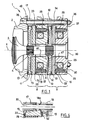
- the braking system 1 represented at figure 1 comprises a frame 2, partially shown, secured to an unseen frame. Inside the frame 2 rotates a shaft 3 of X axis, comprising a drive pulley of an elevator cable. This shaft 3 has at one end two fluted portions 4 and 5.
- the braking system also comprises, in the example under consideration, two brakes 8 and 9 comprising respective brake disks 11 and 12 provided with hubs that can slide on the respective grooved portions 3 and 4 along the axis X of the shaft , while turning with this one.
- the brake discs 11 and 12 are provided at their periphery and on both sides with friction linings 13.
- the brakes 8 and 9 comprise respective movable armatures 15 and 16, which are guided in their displacement in translation along the X axis by spacers 17 for the first brake and 18 for the second, these spacers 17 and 18 being screwed into respective yokes 19 and 20 of the brakes 8 and 9.
- Electromagnets 22 and 23 respectively housed in the yokes 19 and 20 of the brakes 8 and 9 make it possible to attract the corresponding armatures 15 and 16 when electrically energized, in which case the brake disks associated with said armatures can rotate without appreciably slowing down the rotation of the tree 2.
- Springs 29 are arranged in housings of the yokes 19 and 20 to press the plates 15 and 16 against the corresponding brake disks 11 and 12 in the absence of supply of the electromagnets 22 and 23, so that the friction linings 13 then rub against the frame 15 and the frame 2 for the first brake 8 and against the frame 16 and the yoke 19 for the second brake, thus exerting a braking torque on the shaft 3.
- An O-ring 33 is disposed on each yoke 19 or 20 to interpose elastically with the corresponding armature during the power supply of the associated electromagnet, in order to reduce the vibrations and the operating noise of the brake.
- the spacers 17 are hollow and it is the same spacers 18, which allows the passage of rods 34 for fixing the brakes 8 and 9 on the frame 2.
- These rods 34 are parallel to the axis X and are screwed at one end 35 on the frame 2 and each receive at the opposite end 36 a nut coming against the rear face 37 of the yoke 20 of the second brake 9.
- Other fastening systems that the rods 34 could be used .
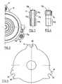
- the spacers 17 have a threaded portion 17a which is screwed into the yoke 19 and a hexagonal head 17b which defines a shoulder 17c. By more or less screwing the spacers 17, it is possible to act on the air gap of the brake 8.
- the spacers 17 have an intermediate portion 17d, cylindrical of revolution, smooth, extending between the head 17b and the threaded portion 17a, which serves to guide the armature 15.
- the spacers 17 each comprise an annular rib 17e projecting beyond the hexagonal head 17b, arranged to engage in a corresponding housing 40 of the frame 2, so as to allow transmission to the chassis 2 of the braking torque exerted on the brakes 8 and 9.
- the spacers 18 differ from the spacers 17 only by the absence of the rib 17e.
- each armature 15 or 16 has at its periphery, as can be seen in FIG. figure 5 three forks 41 arranged at 120 ° from each other, each having an oblong opening 42 for the passage of the corresponding spacer 17 or 18, the width of each opening 42 substantially corresponding to the outer diameter of the cylindrical intermediate portion 17d.
- the oblong openings 42 open, in the example shown, radially outside the corresponding armature 15 or 16, which allows a certain clearance in the radial direction of the spacers 17 and 18 and facilitates the manufacture and assembly of the brakes. 8 and 9.
- the yokes 19 and 20 have respective housings 46 and 47 for the passage of the shaft 3.
- a cap 50 closes the housing 47 of the yoke 20, which reduces operating noise.
- the spacers 18 of the second brake are identical to those of the first and therefore comprise each, as has been partially and schematically represented in FIG. figure 6 an extension formed by an annular rib 18e engaging a corresponding counterbore 52 of the yoke 19 of the first brake 8, so as to allow the torque between the two brakes 8 and 9 to be resumed otherwise than by friction and to further improve the security of the whole.
- the spacers can be given different shapes and, if necessary, use for the braking system a different number of brakes.
Landscapes
- Engineering & Computer Science (AREA)
- Mechanical Engineering (AREA)
- General Engineering & Computer Science (AREA)
- Physics & Mathematics (AREA)
- Electromagnetism (AREA)
- Power Engineering (AREA)
- Braking Arrangements (AREA)
- Cage And Drive Apparatuses For Elevators (AREA)
Claims (9)
- Bremssystem für Elektromotoren insbesondere Aufzugsantriebselektromotoren mit:einem Gehäuse (2),mindestens einer von dem Gehäuse getragenen Bremse (8) mit:wobei das Bremssystem dadurch gekennzeichnet ist, dass Abstandshalter (17) zur Führung der Armierung in ein Bodenstück der Bremse (8) geschraubt sind, wobei die Abstandshalter einen Sechskantkopf (27b) aufweisen, der einen Flansch (17c) und eine Ringrippe (17e), die über den Sechskantkopf hinaus (17b) herausstehend gebildet ist, definiert, wobei die Abstandshalter (17) sich an einem Ende über die Rippe in einem entsprechenden Unterbringungsabschnitt (40) des Gehäuses in Eingriff befinden, um so eine Wiederaufnahme des Drehmoments, das während des Bremsens auf die Bremse ausgeübt wird, durch das Gehäuse zu ermöglichen.mindestens einer Bremsscheibe (11), die durch eine kannelierte Verbindung mit einer vom Motor angetriebenen Welle (3) verbundenen ist,einer entlang der Wellenrotationsachse translatorisch beweglichen Armierung (15)Federn (29), um die Armierung gegen die Scheibe zu drücken,einem Elektromagneten (22), um, wenn gespeist, die Armierung anzuziehen und sie gegen die Federwirkung von der Scheibe wegzurücken,
- System nach Anspruch 1, dadurch gekennzeichnet, dass die Armierung (15) mindestens eine sich in radialer Richtung verlaufende, längliche Öffnung (42) enthält, die von einem entsprechendem Abstandshalter (17) durchquert wird.
- System nach Anspruch 2, dadurch gekennzeichnet, dass die längliche Öffnung (42) an die Umrandung der Armierung mündet.
- System nach einem der vorhergehenden Ansprüche, dadurch gekennzeichnet, dass die Bremse (8) drei Abstandshalter (17) mit jeweils einem Ende (17e) enthält, das sich mit einem entsprechenden Unterbringungsabschnitt (40) des Gehäuses in Eingriff befindet, um so eine Wiederaufnahme des Drehmoments, das während des Bremsens auf die Bremse (8) ausgeübt wird, durch das Gehäuse (2) zu ermöglichen.
- Bremssystem nach einem der vorhergehenden Ansprüche gekennzeichnet durch eine neben die erste (8) gesetzte zweite Bremse (9) mit einer Bremsscheibe (12), die durch eine kannelierte Verbindung mit der vom Motor angetriebenen Welle (3) verbundenen ist, einer entlang der Wellenrotationsachse (X) translatorisch beweglichen Armierung (16), Abstandshaltern (18) der Führung der Armierung, Federn (29) zum Drücken der Armierung gegen die Scheibe und einem Elektromagneten (23), um bei Versorgung mit Strom die Armierung anzuziehen und sie gegen die Federwirkung von der Scheibe wegzurücken.
- System nach einem der vorhergehenden Ansprüche, dadurch gekennzeichnet, dass sich die Abstandshalter (18) dieser zweiten Bremse an einem ein Ende (18e) mit einem entsprechenden Unterbringungsabschnitt (52) des Bodenstückes (19) der ersten Bremse in Eingriff befindet, um so eine Wiederaufnahme des Drehmoments, das während des Bremsens auf die Bremse ausgeübt wird, durch das Bodenstück zu ermöglichen.
- System nach einem der zwei unmittelbar vorhergehenden Ansprüche, dadurch gekennzeichnet, dass das Bremssystem Gewindestangen (34) enthält, welche die Abstandshalter (17, 18) durchqueren und die beiden Bremsen (8, 9) in gegenseitigem Druck halten.
- System nach dem vorhergehenden Anspruch, dadurch gekennzeichnet dass, die Gewindestangen (34) an einem Ende (35) in das Gehäuse (2) geschraubt werden und am gegenüberliegenden Ende (36) das Verschrauben von Muttern erlauben, die sich auf das Bodenstück der zweiten Bremse stützen.
- System nach einem der Ansprüche 5 bis 8, dadurch gekennzeichnet, dass das Bodenstück (20) der zweiten Bremse einen Unterbringungsabschnitt (47) enthält, der die Aufnahme der vom Motor angetriebenen Welle (3) erlaubt, und dass der Unterbringungsabschnitt an einem Ende mit einem Verschluss (50) verschlossen ist.
Applications Claiming Priority (2)
| Application Number | Priority Date | Filing Date | Title |
|---|---|---|---|
| FR0308362 | 2003-07-08 | ||
| FR0308362A FR2857348B1 (fr) | 2003-07-08 | 2003-07-08 | Systeme de freinage a reprise de couple securisee |
Publications (2)
| Publication Number | Publication Date |
|---|---|
| EP1496601A1 EP1496601A1 (de) | 2005-01-12 |
| EP1496601B1 true EP1496601B1 (de) | 2009-07-29 |
Family
ID=33443250
Family Applications (1)
| Application Number | Title | Priority Date | Filing Date |
|---|---|---|---|
| EP04291596A Expired - Lifetime EP1496601B1 (de) | 2003-07-08 | 2004-06-24 | Bremssystem mit sicherer Drehmomentaufnahme |
Country Status (7)
| Country | Link |
|---|---|
| US (1) | US7073641B2 (de) |
| EP (1) | EP1496601B1 (de) |
| CN (1) | CN1578100A (de) |
| AT (1) | ATE438224T1 (de) |
| DE (1) | DE602004022221D1 (de) |
| ES (1) | ES2329789T3 (de) |
| FR (1) | FR2857348B1 (de) |
Cited By (2)
| Publication number | Priority date | Publication date | Assignee | Title |
|---|---|---|---|---|
| EP2535306A1 (de) | 2010-02-10 | 2012-12-19 | Mitsubishi Electric Corporation | Bremsvorrichtung für eine aufzugwinde |
| CN111448402A (zh) * | 2017-12-06 | 2020-07-24 | 华纳电气科技有限公司 | 具有用于密封电枢和电磁体之间的接合面的构件的旋转联接装置 |
Families Citing this family (24)
| Publication number | Priority date | Publication date | Assignee | Title |
|---|---|---|---|---|
| AU2004261143B2 (en) * | 2003-07-25 | 2009-11-05 | Allergan Pharmaceuticals International Limited | A doxycycline metal complex in a solid dosage form |
| US8186486B2 (en) * | 2005-04-01 | 2012-05-29 | Eaton Corporation | Inertia brake |
| WO2007015554A1 (ja) * | 2005-08-01 | 2007-02-08 | Hitachi Construction Machinery Co., Ltd. | 建設機械のドラム回転装置 |
| DE102006022491A1 (de) * | 2006-05-13 | 2008-01-17 | Chr. Mayr Gmbh & Co. Kg | Geräuschdämpfung Bremse |
| DE102007005827B4 (de) | 2007-02-01 | 2024-07-11 | Sew-Eurodrive Gmbh & Co Kg | Vorrichtung und Verfahren für einen Funktionstest einer Bremse |
| EP2297017B2 (de) * | 2008-06-03 | 2024-12-04 | Otis Elevator Company | (elektrischer) einzelbremsbackentest für aufzüge |
| JP5206157B2 (ja) * | 2008-06-30 | 2013-06-12 | オムロン株式会社 | 電磁継電器 |
| JP5163317B2 (ja) * | 2008-06-30 | 2013-03-13 | オムロン株式会社 | 接点装置 |
| CN101367439B (zh) * | 2008-09-19 | 2012-05-23 | 北京航空航天大学 | 一种可重复锁紧装置 |
| DE102010049747B4 (de) * | 2010-10-29 | 2021-05-06 | Sew-Eurodrive Gmbh & Co Kg | Bausatz zur Herstellung unterschiedlicher Elektromotoren einer Baureihe von Elektromotoren und Verfahren zur Herstellung |
| DE102010049748B4 (de) | 2010-10-29 | 2022-09-08 | Sew-Eurodrive Gmbh & Co Kg | Elektromotor |
| DE102010049744B4 (de) * | 2010-10-29 | 2021-04-29 | Sew-Eurodrive Gmbh & Co Kg | Bremse |
| CN102826237B (zh) * | 2012-09-13 | 2015-03-04 | 郑州大学 | 一种磁悬浮飞轮用可重复锁紧装置 |
| US9863486B2 (en) | 2012-12-24 | 2018-01-09 | Borgwarner Inc. | Driven accessory |
| CN104728302A (zh) * | 2013-12-19 | 2015-06-24 | 博格华纳公司 | 带有摩擦离合器和电动马达的附件驱动器 |
| CN104140054B (zh) * | 2014-07-04 | 2016-09-07 | 浙江西子富沃德电机有限公司 | 一种电磁盘式制动器以及装有该电磁盘式制动器的曳引机 |
| JP6235496B2 (ja) | 2015-01-16 | 2017-11-22 | ファナック株式会社 | 回転テーブルとクランプ機構 |
| CN107428397B (zh) * | 2015-01-29 | 2019-12-20 | Pt技术有限公司 | 电磁释放式多盘封闭安全制动器 |
| US10337349B2 (en) | 2016-04-27 | 2019-07-02 | United Technologies Corporation | Anti-windmilling system for a gas turbine engine |
| CN106411040B (zh) * | 2016-10-18 | 2019-01-25 | 中国电子科技集团公司第二十一研究所 | 集成制动器的一体电机 |
| US10359089B1 (en) * | 2018-01-24 | 2019-07-23 | Hamilton Sundstrand Corporation | Proportional control brake |
| WO2019219243A1 (de) * | 2018-05-14 | 2019-11-21 | Sew-Eurodrive Gmbh & Co. Kg | Bremsanordnung für einen elektromotor |
| JP7179312B2 (ja) | 2018-07-30 | 2022-11-29 | ユニパー株式会社 | ウインチ装置 |
| CN112659177B (zh) * | 2020-12-10 | 2023-07-04 | 珠海格力电器股份有限公司 | 制动器及机器人手臂 |
Family Cites Families (12)
| Publication number | Priority date | Publication date | Assignee | Title |
|---|---|---|---|---|
| DE1292735B (de) * | 1967-02-02 | 1969-04-17 | Sueddeutsche Elektromotoren We | Bremsmotor |
| AU4639768A (en) * | 1968-11-18 | 1970-12-17 | West Ate Electrical Industries Limited | Electrically operated brake device |
| CH520285A (de) * | 1969-03-21 | 1972-03-15 | Baumueller Gmbh A | An einem Motorgehäuse angeordnete Einscheibenbremse zum Abbremsen der Motorwelle, insbesondere von Elektromotoren |
| US4142610A (en) * | 1977-11-14 | 1979-03-06 | Eaton Corporation | Self adjusting hoist brake |
| JPS6220922A (ja) * | 1985-07-19 | 1987-01-29 | Ogura Clutch Co Ltd | 負作動形電磁ブレ−キ |
| DE8709409U1 (de) * | 1987-07-09 | 1988-11-10 | Pies, Gerrit, 5650 Solingen | Antriebsmotor |
| FI85907C (fi) * | 1990-03-13 | 1992-06-10 | Kone Oy | Elektromagnetisk broms. |
| US5057728A (en) * | 1990-11-29 | 1991-10-15 | Crown Equipment Corporation | Three step electric brake |
| FR2755084B1 (fr) * | 1996-10-25 | 1998-12-11 | Warner France | Dispositif de freinage a couple de freinage variable |
| DE19733169B4 (de) * | 1997-07-31 | 2005-06-16 | Chr. Mayr Gmbh & Co. Kg | Elektromagnetisch gelüftete Reibungs-Sicherheitsbremse mit zwei unabhängigen Bremskreisen |
| JP2000035064A (ja) * | 1998-07-16 | 2000-02-02 | Tabuchi Tec Kk | ブレーキ内蔵モータ |
| US6439355B1 (en) * | 2000-12-18 | 2002-08-27 | The Hilliard Corporation | Electromagnetic spring-actuated brake system |
-
2003
- 2003-07-08 FR FR0308362A patent/FR2857348B1/fr not_active Expired - Fee Related
-
2004
- 2004-06-22 US US10/872,372 patent/US7073641B2/en not_active Expired - Fee Related
- 2004-06-24 DE DE602004022221T patent/DE602004022221D1/de not_active Expired - Lifetime
- 2004-06-24 ES ES04291596T patent/ES2329789T3/es not_active Expired - Lifetime
- 2004-06-24 AT AT04291596T patent/ATE438224T1/de not_active IP Right Cessation
- 2004-06-24 EP EP04291596A patent/EP1496601B1/de not_active Expired - Lifetime
- 2004-07-06 CN CNA2004100623615A patent/CN1578100A/zh active Pending
Cited By (3)
| Publication number | Priority date | Publication date | Assignee | Title |
|---|---|---|---|---|
| EP2535306A1 (de) | 2010-02-10 | 2012-12-19 | Mitsubishi Electric Corporation | Bremsvorrichtung für eine aufzugwinde |
| CN111448402A (zh) * | 2017-12-06 | 2020-07-24 | 华纳电气科技有限公司 | 具有用于密封电枢和电磁体之间的接合面的构件的旋转联接装置 |
| CN111448402B (zh) * | 2017-12-06 | 2021-08-31 | 华纳电气科技有限公司 | 具有用于密封电枢和电磁体之间的接合面的构件的旋转联接装置 |
Also Published As
| Publication number | Publication date |
|---|---|
| DE602004022221D1 (de) | 2009-09-10 |
| US20050011707A1 (en) | 2005-01-20 |
| EP1496601A1 (de) | 2005-01-12 |
| FR2857348B1 (fr) | 2005-12-02 |
| ATE438224T1 (de) | 2009-08-15 |
| ES2329789T3 (es) | 2009-12-01 |
| FR2857348A1 (fr) | 2005-01-14 |
| US7073641B2 (en) | 2006-07-11 |
| CN1578100A (zh) | 2005-02-09 |
Similar Documents
| Publication | Publication Date | Title |
|---|---|---|
| EP1496601B1 (de) | Bremssystem mit sicherer Drehmomentaufnahme | |
| EP3089898B1 (de) | Trommelbremse mit feststellbremse in doppelservomodos betrieben, fahrzeug mit so einer bremse, und -herstellungsverfahren | |
| FR2695083A1 (fr) | Entraînement par moyeu de roue constitué d'un moteur d'entraînement et d'un réducteur planétaire monté en aval. | |
| EP1324466B1 (de) | Drehmomentübertragungs- und Scheibenbremsenvorrichtung | |
| FR2721264A1 (fr) | Dispositif de commande à vérin hydraulique piloté par un moteur électrique, notamment pour embrayage de véhicule automobile. | |
| EP2816251B1 (de) | Bremse für luftfahrzeugreifen, insbesondere für hubschrauber | |
| EP3175136B1 (de) | Fahrzeugbremsenbetätiger | |
| EP3394963A1 (de) | Bremse für elektrische drehmaschine | |
| FR2762058A1 (fr) | Dispositif d'accouplement elastique entre deux arbres sensiblement alignes | |
| FR3016013A1 (fr) | Actionneur de frein a tambour avec motorisation par emboitement a jeu angulaire | |
| EP3440372A1 (de) | Elektromagnetischer bremssattel mit einer kolbenführung mit verringerter reibung | |
| EP3089900B1 (de) | Getriebeuntersetzung mit elektromotor für eine trommelbremse | |
| FR3057634A1 (fr) | Systeme d'embrayage, et procede de montage d'un systeme d'embrayage | |
| EP1715564A2 (de) | Bremsvorrichtung für die Drehwelle eines Antriebs, wie ein Elektromotor | |
| EP2612049A1 (de) | Drehmomentübertragungsvorrichtung | |
| EP1610026B1 (de) | Bremssattel für eine elektromechanische Scheibenbremse | |
| EP2221494A1 (de) | Vorrichtung zur Fixierung eines Radiallagers einer Getriebewelle eines Kraftfahrzeuges | |
| EP0728906B1 (de) | Elektromotor mit Ruhestrombremsvorrichtung | |
| FR3011051A1 (fr) | Dispositif a rondelles ressorts pour un embrayage a friction | |
| FR2581144A1 (fr) | Amortisseur de torsion, notamment friction d'embrayage pour vehicule automobile. | |
| EP0710781B1 (de) | Kupplungseinheit zwischen zwei Wellen | |
| EP4146509B1 (de) | Manuell betätigter elektromagnetischer aktuator und mit einem solchen aktuator ausgestattetes parkbremsventil | |
| EP3216630B1 (de) | Antriebsachse für schienenfahrzeug, und schienenfahrzeug, das mit einer solchen achse ausgestattet ist | |
| FR2658878A1 (fr) | Dispositif de connexion rapide entre deux portions d'une timonerie, notamment pour vehicule automobile. | |
| EP1691068A1 (de) | Vorrichtung zum Anlassen einer Brennkraftmaschine |
Legal Events
| Date | Code | Title | Description |
|---|---|---|---|
| PUAI | Public reference made under article 153(3) epc to a published international application that has entered the european phase |
Free format text: ORIGINAL CODE: 0009012 |
|
| AK | Designated contracting states |
Kind code of ref document: A1 Designated state(s): AT BE BG CH CY CZ DE DK EE ES FI FR GB GR HU IE IT LI LU MC NL PL PT RO SE SI SK TR |
|
| AX | Request for extension of the european patent |
Extension state: AL HR LT LV MK |
|
| 17P | Request for examination filed |
Effective date: 20050416 |
|
| AKX | Designation fees paid |
Designated state(s): AT BE BG CH CY CZ DE DK EE ES FI FR GB GR HU IE IT LI LU MC NL PL PT RO SE SI SK TR |
|
| 17Q | First examination report despatched |
Effective date: 20070503 |
|
| GRAP | Despatch of communication of intention to grant a patent |
Free format text: ORIGINAL CODE: EPIDOSNIGR1 |
|
| GRAS | Grant fee paid |
Free format text: ORIGINAL CODE: EPIDOSNIGR3 |
|
| GRAA | (expected) grant |
Free format text: ORIGINAL CODE: 0009210 |
|
| AK | Designated contracting states |
Kind code of ref document: B1 Designated state(s): AT BE BG CH CY CZ DE DK EE ES FI FR GB GR HU IE IT LI LU MC NL PL PT RO SE SI SK TR |
|
| REG | Reference to a national code |
Ref country code: GB Ref legal event code: FG4D Free format text: NOT ENGLISH |
|
| REG | Reference to a national code |
Ref country code: CH Ref legal event code: EP |
|
| REG | Reference to a national code |
Ref country code: IE Ref legal event code: FG4D |
|
| REF | Corresponds to: |
Ref document number: 602004022221 Country of ref document: DE Date of ref document: 20090910 Kind code of ref document: P |
|
| REG | Reference to a national code |
Ref country code: CH Ref legal event code: NV Representative=s name: KIRKER & CIE S.A. |
|
| REG | Reference to a national code |
Ref country code: ES Ref legal event code: FG2A Ref document number: 2329789 Country of ref document: ES Kind code of ref document: T3 |
|
| NLV1 | Nl: lapsed or annulled due to failure to fulfill the requirements of art. 29p and 29m of the patents act | ||
| PG25 | Lapsed in a contracting state [announced via postgrant information from national office to epo] |
Ref country code: AT Free format text: LAPSE BECAUSE OF FAILURE TO SUBMIT A TRANSLATION OF THE DESCRIPTION OR TO PAY THE FEE WITHIN THE PRESCRIBED TIME-LIMIT Effective date: 20090729 Ref country code: SE Free format text: LAPSE BECAUSE OF FAILURE TO SUBMIT A TRANSLATION OF THE DESCRIPTION OR TO PAY THE FEE WITHIN THE PRESCRIBED TIME-LIMIT Effective date: 20090729 Ref country code: FI Free format text: LAPSE BECAUSE OF FAILURE TO SUBMIT A TRANSLATION OF THE DESCRIPTION OR TO PAY THE FEE WITHIN THE PRESCRIBED TIME-LIMIT Effective date: 20090729 |
|
| PG25 | Lapsed in a contracting state [announced via postgrant information from national office to epo] |
Ref country code: SI Free format text: LAPSE BECAUSE OF FAILURE TO SUBMIT A TRANSLATION OF THE DESCRIPTION OR TO PAY THE FEE WITHIN THE PRESCRIBED TIME-LIMIT Effective date: 20090729 Ref country code: NL Free format text: LAPSE BECAUSE OF FAILURE TO SUBMIT A TRANSLATION OF THE DESCRIPTION OR TO PAY THE FEE WITHIN THE PRESCRIBED TIME-LIMIT Effective date: 20090729 Ref country code: PL Free format text: LAPSE BECAUSE OF FAILURE TO SUBMIT A TRANSLATION OF THE DESCRIPTION OR TO PAY THE FEE WITHIN THE PRESCRIBED TIME-LIMIT Effective date: 20090729 |
|
| REG | Reference to a national code |
Ref country code: IE Ref legal event code: FD4D |
|
| PG25 | Lapsed in a contracting state [announced via postgrant information from national office to epo] |
Ref country code: PT Free format text: LAPSE BECAUSE OF FAILURE TO SUBMIT A TRANSLATION OF THE DESCRIPTION OR TO PAY THE FEE WITHIN THE PRESCRIBED TIME-LIMIT Effective date: 20091129 Ref country code: BG Free format text: LAPSE BECAUSE OF FAILURE TO SUBMIT A TRANSLATION OF THE DESCRIPTION OR TO PAY THE FEE WITHIN THE PRESCRIBED TIME-LIMIT Effective date: 20091029 |
|
| PG25 | Lapsed in a contracting state [announced via postgrant information from national office to epo] |
Ref country code: RO Free format text: LAPSE BECAUSE OF FAILURE TO SUBMIT A TRANSLATION OF THE DESCRIPTION OR TO PAY THE FEE WITHIN THE PRESCRIBED TIME-LIMIT Effective date: 20090729 Ref country code: CZ Free format text: LAPSE BECAUSE OF FAILURE TO SUBMIT A TRANSLATION OF THE DESCRIPTION OR TO PAY THE FEE WITHIN THE PRESCRIBED TIME-LIMIT Effective date: 20090729 Ref country code: DK Free format text: LAPSE BECAUSE OF FAILURE TO SUBMIT A TRANSLATION OF THE DESCRIPTION OR TO PAY THE FEE WITHIN THE PRESCRIBED TIME-LIMIT Effective date: 20090729 Ref country code: IE Free format text: LAPSE BECAUSE OF FAILURE TO SUBMIT A TRANSLATION OF THE DESCRIPTION OR TO PAY THE FEE WITHIN THE PRESCRIBED TIME-LIMIT Effective date: 20090729 Ref country code: EE Free format text: LAPSE BECAUSE OF FAILURE TO SUBMIT A TRANSLATION OF THE DESCRIPTION OR TO PAY THE FEE WITHIN THE PRESCRIBED TIME-LIMIT Effective date: 20090729 |
|
| PG25 | Lapsed in a contracting state [announced via postgrant information from national office to epo] |
Ref country code: SK Free format text: LAPSE BECAUSE OF FAILURE TO SUBMIT A TRANSLATION OF THE DESCRIPTION OR TO PAY THE FEE WITHIN THE PRESCRIBED TIME-LIMIT Effective date: 20090729 |
|
| PLBE | No opposition filed within time limit |
Free format text: ORIGINAL CODE: 0009261 |
|
| STAA | Information on the status of an ep patent application or granted ep patent |
Free format text: STATUS: NO OPPOSITION FILED WITHIN TIME LIMIT |
|
| 26N | No opposition filed |
Effective date: 20100503 |
|
| PGFP | Annual fee paid to national office [announced via postgrant information from national office to epo] |
Ref country code: ES Payment date: 20100617 Year of fee payment: 7 |
|
| PGFP | Annual fee paid to national office [announced via postgrant information from national office to epo] |
Ref country code: IT Payment date: 20100625 Year of fee payment: 7 |
|
| PG25 | Lapsed in a contracting state [announced via postgrant information from national office to epo] |
Ref country code: GR Free format text: LAPSE BECAUSE OF FAILURE TO SUBMIT A TRANSLATION OF THE DESCRIPTION OR TO PAY THE FEE WITHIN THE PRESCRIBED TIME-LIMIT Effective date: 20091030 |
|
| PGFP | Annual fee paid to national office [announced via postgrant information from national office to epo] |
Ref country code: CH Payment date: 20100630 Year of fee payment: 7 |
|
| PGFP | Annual fee paid to national office [announced via postgrant information from national office to epo] |
Ref country code: DE Payment date: 20100824 Year of fee payment: 7 Ref country code: FR Payment date: 20100715 Year of fee payment: 7 Ref country code: GB Payment date: 20100617 Year of fee payment: 7 |
|
| BERE | Be: lapsed |
Owner name: MOTEURS LEROY-SOMER Effective date: 20100630 |
|
| PG25 | Lapsed in a contracting state [announced via postgrant information from national office to epo] |
Ref country code: MC Free format text: LAPSE BECAUSE OF NON-PAYMENT OF DUE FEES Effective date: 20100630 |
|
| PG25 | Lapsed in a contracting state [announced via postgrant information from national office to epo] |
Ref country code: BE Free format text: LAPSE BECAUSE OF NON-PAYMENT OF DUE FEES Effective date: 20100630 |
|
| REG | Reference to a national code |
Ref country code: CH Ref legal event code: PL |
|
| GBPC | Gb: european patent ceased through non-payment of renewal fee |
Effective date: 20110624 |
|
| PG25 | Lapsed in a contracting state [announced via postgrant information from national office to epo] |
Ref country code: IT Free format text: LAPSE BECAUSE OF NON-PAYMENT OF DUE FEES Effective date: 20110624 |
|
| REG | Reference to a national code |
Ref country code: FR Ref legal event code: ST Effective date: 20120229 |
|
| REG | Reference to a national code |
Ref country code: DE Ref legal event code: R119 Ref document number: 602004022221 Country of ref document: DE Effective date: 20120103 |
|
| PG25 | Lapsed in a contracting state [announced via postgrant information from national office to epo] |
Ref country code: CH Free format text: LAPSE BECAUSE OF NON-PAYMENT OF DUE FEES Effective date: 20110630 Ref country code: DE Free format text: LAPSE BECAUSE OF NON-PAYMENT OF DUE FEES Effective date: 20120103 Ref country code: FR Free format text: LAPSE BECAUSE OF NON-PAYMENT OF DUE FEES Effective date: 20110630 Ref country code: LI Free format text: LAPSE BECAUSE OF NON-PAYMENT OF DUE FEES Effective date: 20110630 |
|
| PG25 | Lapsed in a contracting state [announced via postgrant information from national office to epo] |
Ref country code: GB Free format text: LAPSE BECAUSE OF NON-PAYMENT OF DUE FEES Effective date: 20110624 |
|
| REG | Reference to a national code |
Ref country code: ES Ref legal event code: FD2A Effective date: 20120717 |
|
| PG25 | Lapsed in a contracting state [announced via postgrant information from national office to epo] |
Ref country code: ES Free format text: LAPSE BECAUSE OF NON-PAYMENT OF DUE FEES Effective date: 20110625 |
|
| PG25 | Lapsed in a contracting state [announced via postgrant information from national office to epo] |
Ref country code: CY Free format text: LAPSE BECAUSE OF FAILURE TO SUBMIT A TRANSLATION OF THE DESCRIPTION OR TO PAY THE FEE WITHIN THE PRESCRIBED TIME-LIMIT Effective date: 20090729 |
|
| PG25 | Lapsed in a contracting state [announced via postgrant information from national office to epo] |
Ref country code: LU Free format text: LAPSE BECAUSE OF NON-PAYMENT OF DUE FEES Effective date: 20100624 Ref country code: HU Free format text: LAPSE BECAUSE OF FAILURE TO SUBMIT A TRANSLATION OF THE DESCRIPTION OR TO PAY THE FEE WITHIN THE PRESCRIBED TIME-LIMIT Effective date: 20100130 |
|
| PG25 | Lapsed in a contracting state [announced via postgrant information from national office to epo] |
Ref country code: TR Free format text: LAPSE BECAUSE OF FAILURE TO SUBMIT A TRANSLATION OF THE DESCRIPTION OR TO PAY THE FEE WITHIN THE PRESCRIBED TIME-LIMIT Effective date: 20090729 |