EP1496960B1 - Zurückziehbare sicherheits-infusionsnadel - Google Patents
Zurückziehbare sicherheits-infusionsnadel Download PDFInfo
- Publication number
- EP1496960B1 EP1496960B1 EP03728357A EP03728357A EP1496960B1 EP 1496960 B1 EP1496960 B1 EP 1496960B1 EP 03728357 A EP03728357 A EP 03728357A EP 03728357 A EP03728357 A EP 03728357A EP 1496960 B1 EP1496960 B1 EP 1496960B1
- Authority
- EP
- European Patent Office
- Prior art keywords
- housing
- needle
- key
- placement
- placement location
- Prior art date
- Legal status (The legal status is an assumption and is not a legal conclusion. Google has not performed a legal analysis and makes no representation as to the accuracy of the status listed.)
- Expired - Lifetime
Links
Images


















Classifications
-
- A—HUMAN NECESSITIES
- A61—MEDICAL OR VETERINARY SCIENCE; HYGIENE
- A61M—DEVICES FOR INTRODUCING MEDIA INTO, OR ONTO, THE BODY; DEVICES FOR TRANSDUCING BODY MEDIA OR FOR TAKING MEDIA FROM THE BODY; DEVICES FOR PRODUCING OR ENDING SLEEP OR STUPOR
- A61M25/00—Catheters; Hollow probes
- A61M25/01—Introducing, guiding, advancing, emplacing or holding catheters
- A61M25/06—Body-piercing guide needles or the like
- A61M25/0612—Devices for protecting the needle; Devices to help insertion of the needle, e.g. wings or holders
- A61M25/0637—Butterfly or winged devices, e.g. for facilitating handling or for attachment to the skin
-
- A—HUMAN NECESSITIES
- A61—MEDICAL OR VETERINARY SCIENCE; HYGIENE
- A61M—DEVICES FOR INTRODUCING MEDIA INTO, OR ONTO, THE BODY; DEVICES FOR TRANSDUCING BODY MEDIA OR FOR TAKING MEDIA FROM THE BODY; DEVICES FOR PRODUCING OR ENDING SLEEP OR STUPOR
- A61M25/00—Catheters; Hollow probes
- A61M25/01—Introducing, guiding, advancing, emplacing or holding catheters
- A61M25/06—Body-piercing guide needles or the like
- A61M25/0612—Devices for protecting the needle; Devices to help insertion of the needle, e.g. wings or holders
- A61M25/0631—Devices for protecting the needle; Devices to help insertion of the needle, e.g. wings or holders having means for fully covering the needle after its withdrawal, e.g. needle being withdrawn inside the handle or a cover being advanced over the needle
-
- A—HUMAN NECESSITIES
- A61—MEDICAL OR VETERINARY SCIENCE; HYGIENE
- A61M—DEVICES FOR INTRODUCING MEDIA INTO, OR ONTO, THE BODY; DEVICES FOR TRANSDUCING BODY MEDIA OR FOR TAKING MEDIA FROM THE BODY; DEVICES FOR PRODUCING OR ENDING SLEEP OR STUPOR
- A61M5/00—Devices for bringing media into the body in a subcutaneous, intra-vascular or intramuscular way; Accessories therefor, e.g. filling or cleaning devices, arm-rests
- A61M5/178—Syringes
- A61M5/31—Details
- A61M5/32—Needles; Details of needles pertaining to their connection with syringe or hub; Accessories for bringing the needle into, or holding the needle on, the body; Devices for protection of needles
- A61M5/3205—Apparatus for removing or disposing of used needles or syringes, e.g. containers; Means for protection against accidental injuries from used needles
- A61M5/321—Means for protection against accidental injuries by used needles
- A61M5/3243—Means for protection against accidental injuries by used needles being axially-extensible, e.g. protective sleeves coaxially slidable on the syringe barrel
- A61M5/3257—Semi-automatic sleeve extension, i.e. in which triggering of the sleeve extension requires a deliberate action by the user, e.g. manual release of spring-biased extension means
Definitions
- the present invention relates to a safety infusion needle assembly and more particularly to an infusion needle assembly whose needle is automatically retractable into the housing of the needle assembly after use for preventing the contaminated needle from further exposure.
- U.S. patent 5,514,971 discloses a butterfly needle assembly whose needle is manually retracted into the housing. A retaining pin that biases against the body of the needle springs down when the needle clears it to prevent the retracted needle from further usage.
- U.S. patent 5,746,215 discloses an IV needle assembly that has a needle that is automatically retractable.
- a complicated system that includes rear and forward locking tabs at the needle hub coact with locking ribs at the needle housing for maintaining the needle at its extended or retracted position.
- an extended bridge with two opposite portions has to be compressed by the user and be flattened.
- U.S. patent 5,779,679 discloses a winged IV needle assembly that includes a pair of additional wings fitted with appropriate tabs for coacting against contact lugs at the needle hub for retracting the needle hub and its attached needle into the housing.
- U.S. patent 5,968,016 discloses a winged needle device that requires the user to pull the wings in opposite direction to each other in order to deform the latches that hold the catch of the needle in place, so that the needle is retracted into the housing by a tensioned elastic tube.
- U.S. patent 6,210,371 discloses a device that is similar to the'679 device in that an additional pair of wings, with the appropriate contact and tabs, is used for releasing the catch portion of the needle from catches at the housing to retract the needle into the housing.
- WO 99/16488 discloses a retractable needle device that has a housing 20 having only one open end to which a catheter 80 is attached. The needle 60 for insertion into the patient along with the catheter are connected to a needle hub, which is biased by a spring 69 backwards into the housing, when the trigger 34 is pressed by the user.
- the improvement of the device is that a collapsible bladder 96 is provided at the back end of the housing 20, so that when the trigger is pushed, the needle is not retracted too quickly due to the damping afforded to the needle hub by the collapsible bladder.
- the device has a close ended housing and no safety feature for to prevent the inadvertent pressing of the trigger mechanism for retracting the needle.
- the present invention winged needle device aims to improve upon the above-noted prior art devices, both in terms of simplicity in construction and use.
- the contaminated needle of an IV or butterfly needle device is designed with an automatic retracting mechanism that is activated when the user pushes a button, or key, in a given direction. Once the mechanism is pushed or actuated, the needle is automatically retracted into the housing, and remains confined within the housing.
- the housing of the needle device of the instant invention is formed with a passage that communicates with the bore of the housing.
- the passage may be in the form of an upraised well, at either the front end or the rear portion of the housing.
- the passage may be in the form of a sleeve orthogonal to the housing.
- a push mechanism in the form of a push button may be fitted into the well.
- the button may be in the form of a base that has extending therefrom two legs into the well.
- the inside opposing portions of the two legs may converge at their distal ends so that the opening formed by the two legs is non-uniform, as the space or aperture defined by the inner opposing walls of the two legs that are not converged towards each other has a dimension that is greater than the space defined by the converging inner portions of the two legs.
- the well may be formed on the housing such that, when the push mechanism is inserted thereinto, the different dimensioned spaces or apertures formed by the two legs would selectively intersect the bore of the housing, as the button and more specifically the space defined by the two legs of the button is in a transverse, or orthogonal, relationship to the longitudinal axis of the housing.
- each of the legs of the push button there may be formed at least two one-way notches that coact with a corresponding catch extending from the inside wall of the well.
- the notches may be formed at appropriate locations along the legs so that different placement locations are defined for the push button, relative to the housing.
- placement locations represent a first position whereat the space defined by the converged inner portions of the two legs intersects the bore of the housing.
- the second placement location is defined when the push button is further positioned toward the housing so that the space defined by the inner non-converging portions of the two legs intersects the bore of the housing.
- a needle assembly that has a needle hub and a needle extending therefrom is slidably fitted within the bore of the housing.
- the needle hub may have a collar or a rib at a portion thereof that coacts with or abuts against a bias element in the housing such as for example a tensioned spring or elastic tube. While the one side of the collar is being biased by the tensioned bias element, the other side of the collar may be abutted by the converged legs of the push button so that the needle extending from the needle hub continues to extend out of the housing for use with a patient at the first placement location of the push button.
- the push button can be moved closer relative to the housing so that, in the case that it is fitted to a well upraised from the housing, the top of the push button becomes flush with the top rim of the well.
- the space defined by the non-converging portions of the legs extending from the button may intersect the bore of the housing such that the collar about the needle hub would pass through the space due to the biasing force exerted by the bias element. Consequently, as the needle hub is biased toward the end of the housing, the needle that extends from the needle hub can be retracted within the housing.
- a stopper at the end of the housing may maintain the front portion of the needle hub within the housing, as the collar abuts the stopper. The contaminated needle may therefore be retained within the housing.
- a safety lock in the form of a safety button or plug, may be fitted to a cavity of the push button. While the push button is at its first placement location, the space defined by the converged portions of its legs may intersect the bore of the housing.
- the safety lock may ordinarily biased away from the cavity of the push button so that it prevents the push button from being pushed into the well. It is only after the needle has been withdrawn from the patient and the safety lock pushed into the cavity of the push button that the push button may be pushed into the well to its second placement location where the space defined by the non-converging portions of its legs intersects the bore of the housing. Coacting mechanisms in the form of notches at the legs and catches at the inner wall of the well maintain the push button at the respective first and second placement locations.
- a second embodiment of the instant invention needle device may utilize a push button that, in addition to being able to be selectively positioned at first and second placement locations, also has flaps that prevent the needle hub from completely passing out of the housing, once the push button is pressed to its placement location that allows retraction of the needle into the housing.
- the push button may be located at the end portion of the housing.
- needle device may integrate a sleeve at the distal portion of the housing.
- a key may be inserted to the sleeve and is movable to at least a first and second placement location orthogonal to the longitudinal axis of the housing.
- the key may be formed with a non-uniform opening, with differently dimensioned apertures, one of which would prevent the movement of the needle hub, while the other would allow the needle hub to pass through for retracting the needle into the housing.
- Coacting teeth at the sleeve and key may maintain the placement of the key until the user manually pushes the key. Further, the teeth at the key may be one-way teeth, so that once pushed to the placement location enabling the retraction of the needle, the key could no longer be repositioned to its first placement location.
- Fig. 1 is a perspective view of a first embodiment of the instant invention needle device
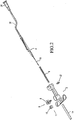
- Fig. 2 is a disassembled view of the needle device of Fig. 1 ;
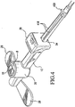
- Fig. 3 is a perspective view of the Fig. 1 device with the needle having been retracted into the housing;
- Fig. 4 is a back view of the Fig. 3 device
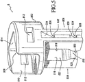
- Fig. 5 is a perspective view of the push mechanism of the Fig. 1 device
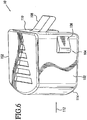
- Fig. 6 is a perspective view of a safety lock for the Fig. 1 device
- Fig. 7 is an exemplar stopper used in the Fig. 1 device
- Fig. 8 shows the needle assembly of the instant invention device of Fig. 1
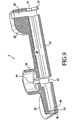
- Fig. 9 is a cut-away exposed view of the housing of the Fig. 1 device
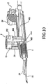
- Fig. 10 is a cut-away view of the device of Fig. 1 showing the needle being extended out for usage;
- Fig. 11 is a back view of the Fig. 1 device showing the interaction between the push mechanism and the needle hub of the device;
- Fig. 12 is a cut-away side view of the device of Fig. 1 showing the needle having been retracted within the housing;
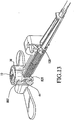
- Fig. 13 is a semi cut-away back view of the needle device of Fig. 1 showing the needle having been retracted within the housing of the device;
- Fig. 14 is a perspective view of a second embodiment of the needle device of the instant invention.
- Fig. 15 is an exposed view of the various elements of the needle device of the second embodiment of the instant invention.
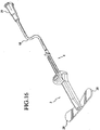
- Fig. 16 is a view of the needle having been retracted into the housing for the second embodiment needle device of the instant invention.
- Fig. 17 is a perspective rear view of the needle device of Fig. 16 ;
- Fig. 18 is the push mechanism of the second embodiment device
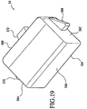
- Fig. 19 is the safety stop mechanism for the needle device of the second embodiment
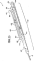
- Fig. 20 is a perspective view of the needle assembly of the needle device of the second embodiment
- Fig. 21 is a cut-away view of the housing of the second embodiment needle device of the instant invention.
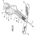
- Fig. 22 is a semi cut-away view of the second embodiment of the needle device of the instant invention.
- Fig. 23 is a semi cut-away view of the back portion of the second embodiment of the needle device of the instant invention.
- Fig. 24 is a semi cut-away view of the needle device of the second embodiment of the instant invention showing that the needle has been retracted within the housing;
- Fig. 25 is a semi cut-away back view of the second embodiment needle device of the instant invention.
- Fig. 26 illustrates the push mechanism of a third embodiment of the needle device of the instant invention
- Fig. 27 illustrates the sleeve of the third embodiment needle device of the instant invention
- Fig. 28 shows the needle assembly of the third embodiment needle device of the instant invention
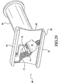
- Fig. 29 is a semi cut-away back view of the housing of the third embodiment needle device of the instant invention.
- Fig. 30 is a semi cut-away front view of the third embodiment needle device of the instant invention.
- Fig. 31 illustrates the needle device of the third embodiment of the instant invention, with the sleeve being exposed to show the interaction between the catch at the sleeve and the teeth at the key;
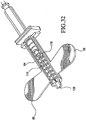
- Fig. 32 is a semi cut-away view showing the needle having been retracted within the housing for the third embodiment needle device of the instant invention.
- the IV or butterfly needle device of the instant invention is shown to have a housing 2, a needle assembly 4, a bias element 6 in the form of a spring, a push mechanism 8, a safety lock element 10 and a stopper element 12.
- a sheath 14 is used to cover the needle 16 before the device is used.
- An infusion tube (or medicament line) 18 is mated to the aft portion of the needle assembly 4.
- a luer connector 20 at the end of the infusion line 18 provides coupling to either a fluid source or a fluid storage.
- housing 2 includes a longitudinal housing proper 22 that has a first (front or distal) end 24 and a second (rear or proximal) end 26.
- Foldably extending from the front end 24 of housing 22 are two wings 28.
- a bore 30 extends throughout the length of housing 22, with a first opening 32 provided at front end 24 and a second opening 34 provided at rear end 26 of housing 22.
- a clear path extends from front opening 32 through bore 30 to rear opening 34.
- housing 22 Integrally rising from housing 22 at the front or mid section thereof is a well structure 36.
- Housing 22 has also a raised portion 38 integrated to its proximal end.
- a void 40 is provided within upraised portion 38 orthogonal to the longitudinal axis of housing 22 for intersecting bore 30.
- Well 36 likewise has a passage 42 that communicates with bore 30.
- passage 42 is orthogonal to the longitudinal axis of housing 22 and intersects bore 30.
- catch 44 Further shown within well 32, at approximately the mid section thereof, is a catch 44. The purpose of catch 44 will be discussed later.
- needle assembly 4 Slidably fitted within bore 30 of housing 22 is needle assembly 4.
- needle assembly 4 has a needle hub 402 having attached thereto needle 16.
- Needle hub 402 has a front end extension 404 to which needle 16 is attached and a rear end 406 to which infusion line 18 is coupled.
- a collar or rib 408 is formed at the end of extension 404.
- Collar 408 has a given dimension so that spring 6, when fitted into bore 30, is booked-ended by inner surface 46 at front end 24 of housing 22 and the front surface 410 of collar 408.
- Collar 408 has a rear surface 412, which becomes the front boundary of a groove 414 formed on the needle hub.
- the remaining portion 416 of the needle hub is configured to have a substantially rectangular guide configuration for the instant embodiment, with the top surface of the needle hub having respective top edges 418 that slants from the front to the rear, so as to form a declining surface.
- a wall or rib 420 is formed at the very end of surface 418 .
- the dimension of wall 420 may be substantially the same as opening 34, thereby allowing a substantial portion of needle hub 402 to pass out of housing 22.
- the push element or mechanism 8 of the first embodiment of the instant invention needle device is shown to comprise a push button or push button key having a base 802 with two legs 804 and 806 extending therefrom.
- Push button base 802 is shown to have a shape that enables it to slidably fit within well 36 of housing 22.
- a cavity or void 808 is formed at base 802. The dimension of cavity 808 is such that the safety lock stop 10 ( Fig. 6 ) is fittable thereinto.
- safety stop 10 is in the shape of a plug that has two sidewalls 102 that slidably fit to the inner sidewalls 810 of push button 8.
- a bias finger 108 extends from back wall 110 of safety stop 10 so that once plug 10 is fitted to cavity 808, unless a force is exerted against safety stop 10 along the direction as indicated by directional arrow 112, bias finger 108 will maintain safety stop 10 at the position as shown for example in Fig. 1 , so that the front portion 114 of safety stop 10 acts against the top edge or rim of well 36 to prevent push button key 8 from being pushed into well 36.
- finger 108 biases against wall 814 of the base of push button key 8.
- legs 804 and 806 extend from base 802 of push button key 8. As shown in Fig. 5 , the inside walls, as designated by 816, of legs 804 and 806 converge toward each other at the respective distal portions of the legs. Thus, the space 818 defined between opposing inner walls 820 is smaller than the space 822 defined by opposing inner walls 816. In fact, space 818 is formed to have a dimension that allows the distal ends of legs 804 and 806 to mate with groove 414 of needle hub 402, and yet at the same time coacts against the back surface 412 of collar 408 so as to prevent the movement of needle assembly 4 within bore 30 of housing 22. Space 822, on the other hand, is formed to have a dimension that is greater than the dimension of collar 408, so that collar 408 would pass between legs 804 and 806 by way of space 822, if collar 408 were to be aligned with space 822.
- each of legs 804 and 806 there is a longitudinal opening that includes at least two notches 824 and 826.
- Notch 824 is formed by a flat base 828 intersecting an incline 830.
- Notch 26 is formed by a flat base 832 intersecting an incline 834.
- corresponding notches are formed on the outer wall of leg 804.
- push button key is shown to be inserted to well 36, with legs 804 and 806 straddling the portion of needle hub formed by groove 414.
- notch 824 of leg 806 of the push button key is shown to be engaged to catch 44 extending from the inner wall of well 36.
- a corresponding catch extends from the opposing inner sidewall of well 36 and engages with the corresponding notch 824 formed on leg 804.
- push button key 8 more specifically base 802 thereof, extends out of the mouth of well 36, with catch 44 engaged to notches 824.
- needle 16 is fixedly extending out of opening 32 of housing 2, and can be used for insertion to a patient.
- Stopper 12 is a resilient member that is molded from an elastic material such as rubber so that its supports 122 and 124 that connect its top 126 to its base 128 act as springs to enable top 126 to move relative to base 128 along the directions as shown by bidirectional arrow 130. Stopper element 12 is dimensioned such that it fits in groove 40 of upraised member 38 at the back end of housing 22. Also, the side or cross section of stopper 12, designated 132, is molded to have a dimension that is slightly less than the width of groove 414. Thus, given its elasticity, the bottom of base 128 will continuously bias against the inclined edges 418 of needle hub 416 until groove 414 is aligned beneath it. At which time, base 128 will fall within groove 414 and abut against the back surface 412 of collar 408 to thereby stop any further movement of needle hub 402.
- Figs. 12 and 13 show that needle 16 has been retracted within housing 2, so that the tip of the needle is no longer exposed to the environment.
- base 802 of push button key 8 has been pushed within well 36 so that its top is flush with the mouth of well 36.
- catch 44 extending from the inside wall of well 36 is engaged to notch 826.
- push button key 8 could no longer be moved to the first or higher placement location as shown in Figs. 10 and 11 .
- push button key 8 is fixedly maintained at the placement location shown in Figs. 12 and 13 .
- safety lock 10 has to be pushed by the user in a direction toward the back of housing 22 so that it clears the top rim of well 36.
- the user pushes push button key 8 downwards until catch 44 engages notch 826.
- the space 822 defined between legs 804 and 806 becomes aligned with the longitudinal axis of housing 22 so that it intersects bore 30.
- needle hub 402 is pushed backwards to thereby retract needle 16 within housing 22.
- FIG. 14-25 A second embodiment of the needle device of the instant invention is shown in Figs. 14-25 . Elements for the second embodiment needle device that are the same or similar to those of the first embodiment are labeled the same.
- the needle device of the second embodiment is similar to the first embodiment needle device except for its push mechanism, its lack of a stopper element, and the portion of the housing that encases the stopper element.
- the second embodiment needle device instead of a well positioned at the front or mid section of the housing into which a push button key is inserted, the second embodiment needle device has at the rear portion of housing 22 an enlarged well portion 50. Fitted to the well of portion 50 is a push mechanism or key 52.
- a safety lock 54 interacts with push key 52 to ensure that key 52 would not be inadvertently pushed completely into the passage provided by well 50 to automatically retract needle 16 into housing 22.
- push key 52 has a base or a top portion 520 that includes a void or cavity 522 to which safety lock 54 is fitted. Similar to the push key of the first embodiment, push key 52 of Fig. 18 has two legs 524 and 526. As shown in Fig. 18 , on the outside wall of leg 526 there are provided two notches 528 and 530. Each of notches 528 and 530 has a planar base and an incline intersecting therewith to form the notch. Although not shown, similar notches are formed on the outer wall of leg 524.
- a non-uniform opening in the form of different dimensioned spaces, are formed between the opposing inner walls of legs 524 and 526.
- a space 532 defined by converging opposing walls 534 and 536.
- Another space 538 is defined by the non-converging opposing inner walls 540 and 542 of legs 524 and 526, respectively.
- flaps 544 and 546 there is moreover extending from the opposing inner sidewalls of legs 524 and 526 two extending flaps 544 and 546. The purpose of flaps 544 and 546 is described later.
- Safety lock 54 which may take the form of a plug fitted to cavity 522 of push key 52, has a front surface 560, two side surfaces 562 and 564, and a back surface 566. Extending from the respective side surfaces are inclining extensions 568 and 570. An elastic flap or finger 572 is formed at the back surface 566 of safety lock 54. Similar to the biasing flap of the safety lock of the first embodiment, flap 572 biases against back surface 552 when safety lock 54 is mated to cavity 522. Once inserted to cavity 522, extensions 568 and 570 would engage with slots 550 and 548, respectively, so that safety plug 54 could no longer be removed from base 520 of push key 52.
- the needle assembly of the second embodiment is substantially the same as the needle assembly of the embodiment shown in Fig. 8 , except for the top edges 418 of the needle hub not inclining from the front to the back. Moreover, an additional groove 422 is defined between the rearmost surface 424 of the guide portion 426 of the needle hub and the front surface 428 of the rear rib 420.
- a catch 502 that coacts with notches 528 and 530 at the outer wall of leg 524 of push key 52.
- a similar catch 502 is provided on the wall opposing inner wall 504 of well 50.
- a back wall 506 of well 50 defines an opening 508 that has a dimension that allows guide 426 of needle hub 402 to pass through.
- opening 32 at the front end of housing 22 enables needle 16 to extend out of housing 22 for use with a patient.
- the needle device of the second embodiment before use, is shown in Figs. 14 , 22 and 23 .
- the needle device of the second embodiment of the instant invention is best illustrated by Fig. 22 in which the needle assembly is shown to be maintained at a fixed position relative to housing 22 with needle 16 extending out of opening 32. In this position, the bias spring element 6 is compressed between the inner wall at the front end of housing 22 and front surface 410 of collar 408. Note also that base 520 of push key 52 is positioned above the mouth of well 50.
- safety lock 54 due to flap 72 biasing against back wall 552 of push key 52, extends away from push key 52 so that the outermost portion of its underside 554 abuts the top surface of well 50, thereby preventing any inadvertent push down of push key 52 into well 50.
- needle assembly 4 is fixed at the position as shown in Fig. 22 due to the interaction between push key 52 and needle hub 402.
- catches 502 extending from the inner walls of well 50 mate with the corresponding notches 528 of legs 524 and 526, so that key 52 is fixed at the placement location as shown in Fig. 23 .
- the needle assembly 4 is fixedly held in position in housing 22.
- flaps 544 and 546 come into abutting relationship with rear surface 412 of collar 408, thereby stopping any further backward movement of the needle assembly. Further, due to the tendency to return to the natural position due to their elastic nature, flaps 544 and 546 become mated to groove 414 of the needle hub to fixedly retain the needle assembly relative to housing 22, thereby lockingly retaining needle 16 within housing 22.
- a third embodiment of the needle device of the instant invention is discussed with reference to Figs. 26-32 .
- the passage to the bore of the housing is provided by means of a sleeve 60, and the coacting key 62 slidably fitted thereinto.
- sleeve 60 with its rear wall not shown, is integrally connected to the rear portion of a needle housing 64.
- wings 66 are attached to the sides of housing 64.
- Sleeve 60 is formed by two parallel walls, with the back wall not shown, sandwiched by a top 68 and a base 70.
- a catch 72 Integrated to top 68 is a catch 72 that, due to its construction, is capable of flexing upwards to give way when contacted at its incline surface 74.
- An opening 76 is formed at front wall 78 to provide a passage to the interior bore of housing 64.
- Key 62 which is slidably inserted to sleeve 60 in the direction as indicated by directional arrow 80, is shown in Figs. 26 and 27 .
- Key 62 has a non-uniform opening 82 that includes spaces of different dimensions.
- opening 82 comprises a first space defined by its opposed interior wall portions 86 and 88.
- a second space 90 is defined by semi-circular opposing inner walls 92 and 94.
- There is yet a further space 96 which is defined by opposing inner walls 98 and 100.
- At the upper portion of key 62 there is a slot 102 formed with defined one-way notches 104, 106 and 108. These notches are each formed to fittingly mate with tooth 73 of catch 72, with incline 74 of catch 72 adaptable to fittingly contact the respective inclines 105, 107 and 109 of notches 104, 106 and 108.
- the needle assembly of the third embodiment of the needle device of the instant invention is shown in Fig. 28 to have a needle 110 extending from a needle hub 112. Connected to the other end of needle hub 112 is a luer 114 that is connectable to an infusion line 18. Needle hub 112 has a guide portion 116 that has two flanges 118 extending longitudinally therealong. A first groove 120 is formed between the rear end of guide portion 116 and the front surface of connector 114. A second groove 122 is formed between the front end 124 of guide portion 116 and a rib or collar 126.
- Fig. 30 shows the positioning of the needle assembly vis-a-vis housing 64 with needle 110 extending from the front opening 128 of needle housing 64.
- a bias element in the form a spring 130 is compressed between the inner surface of the front end of syringe 64 and the front surface of collar 126.
- the needle assembly, particularly guide portion 116 is maintained in the position as shown in Fig. 30 by key 62 being positioned at the shown placement location.
- the distal portion of key 64 as defined by space 84, intersects the bore of needle housing 64 so that the converged opposing inner walls of key 62 that define space 84 are mated to groove 120.
- tooth 73 of catch 72 is mated to notch 108 when key 62 is fitted to sleeve 60 at the placement location shown in Fig. 30 .
- the user can insert needle 110 into a patient for either infusion or withdrawing of blood.
- space 90 of opening 82 becomes aligned with the bore of needle housing 64.
- space 90 is configured to have a larger dimension than guide portion 116 of needle hub, due to the biasing force exerted by spring 126, the needle hub is pushed backwards to retract needle 110 into needle housing 64, as shown in Fig. 32 .
- key 62 is pushed further per directional arrow 128 so that tooth 173 mates with notch 104.
- space 96 is aligned with the longitudinal axis of needle housing 64, it mates with groove 122.
- no reverse movement of key 62 is possible due to the abutting relationship of tooth 73 with notch 104, needle 110 is fixedly retained within housing 64.
Landscapes
- Health & Medical Sciences (AREA)
- Life Sciences & Earth Sciences (AREA)
- Biophysics (AREA)
- Pulmonology (AREA)
- Engineering & Computer Science (AREA)
- Anesthesiology (AREA)
- Biomedical Technology (AREA)
- Heart & Thoracic Surgery (AREA)
- Hematology (AREA)
- Animal Behavior & Ethology (AREA)
- General Health & Medical Sciences (AREA)
- Public Health (AREA)
- Veterinary Medicine (AREA)
- Infusion, Injection, And Reservoir Apparatuses (AREA)
Claims (18)
- Nadelvorrichtung, die Folgendes umfasst:ein Gehäuse (2), das ein erstes Ende (24) mit einer ersten Öffnung (32) und ein zweites Ende (26) mit einer zweiten Öffnung (34) aufweist;eine Nadeleinheit (4), die eine Nadel (16) aufweist, die an einen Nadelanschluss (402) angebracht ist, der verschiebbar in das Gehäuse (2) eingepasst ist, wobei die Nadel durch die erste Öffnung (32) ausgefahren werden kann und der Nadelanschluss durch die zweite Öffnung (34) geführt werden kann;ein Vorspannelement (6) in dem Gehäuse, um eine Vorspannkraft gegen den Nadelanschluss in Richtung des zweiten Endes anzuwenden; wobei die Nadelvorrichtung dadurch gekennzeichnet ist, dass sie Folgendes umfasst:ein Schlüsselmittel (8, 52), das beweglich an das Gehäuse angepasst ist, in einer ersten Anordnung, die im Wesentlichen orthogonal zu der Längsachse des Gehäuses ist, um die Nadeleinheit in einer ersten Stellung bezüglich des Gehäuses zu halten, in der die Nadel aus der ersten Öffnung heraus ausgefahren ist, wobei das Schlüsselmittel in eine zweite Anordnung betätigt werden kann, die im Wesentlichen orthogonal zu der Längsachse des Gehäuses ist, um das Zurückziehen der Nadel in das Gehäuse zu ermöglichen, aufgrund dessen, dass die Nadeleinheit durch das Vorspannelement vorgespannt ist; undSicherheitsmittel (10, 54), die mit dem Schlüsselmittel (8) zusammenwirken, um eine versehentliche Betätigung des Schlüsselmittels aus der ersten Anordnung in die zweite Anordnung zu verhindern.
- Nadelvorrichtung nach Anspruch 1, die weiterhin Folgendes umfasst:einen Stopper (12), der an dem zweiten Ende (26) des Gehäuses (2) positioniert ist und einen Teil (128) aufweist, der kontinuierlich gegen den Nadelanschluss vorspannt und gegen einen Kragen (408) des Nadelanschlusses zusammenwirkt, um zu verhindern, dass der Nadelanschluss vollständig aus der zweiten Öffnung (34) heraus geführt wird, wenn die Nadel (16) in das Gehäuse zurückgezogen wird.
- Nadelvorrichtung nach Anspruch 1, wobei das Schlüsselmittel (8, 52) eine Basis (802, 520) mit zwei Füßen (804, 806; 524, 526), die sich von dieser erstrecken, umfasst, wobei die Innenwände (816, 816; 540, 542) der Füße jeweils gegenüber liegende Teile aufweisen, die sich einander annähern; und
wobei der Nadelanschluss (402) einen länglichen Körper umfasst, der einen Kragen (408) aufweist, der an den sich annähernden gegenüber liegenden Teile der Füße anliegt, wenn das Schlüsselmittel (8) sich in der ersten Anordnung befindet, so dass die Nadeleinheit in der ersten Stellung zum Ausfahren der Nadel aus der ersten Öffnung des Gehäuses heraus gehalten wird. - Nadelvorrichtung nach Anspruch 3, wobei das Gehäuse einen erhobenen Schacht (36, 50) aufweist und wobei die Basis (802, 520) dazu konfiguriert ist, in den Schacht (36, 50) zu passen, wobei die Außenwand jedes der Füße (804, 806; 524, 526) der Basis eine Kerbe (824, 528) aufweist, die mit einer Nase (44, 502) von der Innenwand des Schachts (36, 50) zusammenwirkt, um die sich annähernden gegenüber liegenden Teile der Füße in einer Anliegebeziehung mit dem Kragen zu halten, wenn das Schlüsselmittel sich in der ersten Anordnung befindet, wobei mindestens ein Teil der Basis sich in der ersten Anordnung über dem Eingang des Schachts befindet.
- Nadelvorrichtung nach einem der Ansprüche 1 bis 4, wobei das Schlüsselmittel (8, 52) eine Basis (802, 520) umfasst, die eine Aussparung (808, 522) aufweist, in die das Sicherheitsmittel (10, 54) vorgespannt eingepasst wird, wobei das Sicherheitsmittel eine Arretierungstaste (10, 54) umfasst, die in die Aussparung der Basis bewegt werden kann, wobei die Arretierungstaste eine Abwärtsbewegung der Basis verhindert, wenn sie sich nicht in der Aussparung der Basis befindet, so dass die Arretierungstaste, bevor das Schlüsselmittel in die zweite Anordnung bewegt werden kann, in die Aussparung der Basis bewegt werden muss.
- Nadelvorrichtung nach einem der Ansprüche 1 bis 5, wobei das Vorspannelement eine Feder (6) umfasst, wobei die Nadelvorrichtung weiterhin Folgendes umfasst:ein Paar Flügel (28), die an dem Gehäuse angebracht sind.
- Nadelvorrichtung nach Anspruch 2, die weiterhin Folgendes umfasst:eine Nut (414), die auf dem Nadelanschluss (402) neben dem Kragen (408) ausgebildet ist;wobei der Stopper (12) in die Nut fällt und an dem Kragen anliegt, wenn die Nadel in das Gehäuse zurückgezogen wird, wenn der Schlüssel in die zweite Anordnung bewegt wird.
- Nadelvorrichtung nach Anspruch 4, wobei jeder der Füße (804, 806, 524, 526) eine zweite Kerbe (826, 530) aufweist, die mit der Nase (44, 502) von der Innenwand des Schachts zusammenwirkt, wenn das Schlüsselmittel (8, 52) sich in der zweiten Anordnung befindet, wobei das Zusammenspiel zwischen der zweiten Kerbe und der Nase verhindert, dass die Basis zurück in die erste Anordnung bewegt wird.
- Nadelvorrichtung nach einem der Ansprüche 1 bis 8, wobei das Gehäuse Folgendes umfasst:eine Bohrung (30), die sich in Längsrichtung entlang des Gehäuses (22) erstreckt, und einen Durchlass (42), der orthogonal zu der Längsachse des Gehäuses ist, in Verbindung mit der Bohrung des Gehäuses; undwobei das Schlüsselmittel (8, 52, 62) beweglich in den Durchlass des Gehäuses eingepasst wird, wobei das Schlüsselmittel in mindestens die erste Anordnungsposition und die zweite Anordnungsposition bezüglich des Gehäuses bewegt werden kann, wobei das Schlüsselmittel mindestens zwei (818, 822; 532, 53, 84, 90) Durchbrüche mit unterschiedlichen Abmessungen aufweist, wobei einer (818, 532, 84) der Durchbrüche eine Abmessung aufweist, die die Bewegung des Nadelanschlusses verhindert, um den Ausfahrzustand der Nadel aus der ersten Öffnung des Gehäuses heraus aufrechtzuerhalten, wobei der andere (822, 538, 90) der Durchbrüche eine Abmessung aufweist, die das Durchführen des Nadelanschlusses ermöglicht, wobei die Bewegung des Schlüsselmittels im Wesentlichen orthogonal zu der Längsachse des Gehäuses ist.
- Nadelvorrichtung nach Anspruch 9, wobei der Durchlass eine Manschette (60) am zweiten Ende des Gehäuses (64) umfasst und
wobei das Schlüsselmittel einen Schlüssel (62) umfasst, der in der Manschette verschiebbar ist und mindestens zwei Zähne (104, 106, 108) aufweist, die jeweils mit einer Nase (72, 73) an der Manschette in Eingriff gebracht werden können, so dass der eine Durchbruch (94) sich mit der Bohrung (76) des Gehäuses überkreuzt, wenn der Schlüssel sich in der ersten Anordnungsposition befindet und ein erste der Zähne (108) mit der Nase (72, 73) in Eingriff ist, und wobei der andere Durchbruch (90) sich mit der Bohrung des Gehäuses überkreuzt, wenn der Schlüssel in die zweite (106) Anordnungsposition bewegt wird, wobei ein zweiter (106) der Zähne mit der Nase (72, 73) in Eingriff kommt, wenn der Schlüssel sich in der zweiten Anordnungsposition befindet, wobei die Zähne in eine Richtung ausgerichtete Zähne sind, um zu verhindern, dass der Schlüssel aus der zweiten Verlagerungsposition zurück in die erste Verlagerungsposition bewegt wird, sobald der Schlüssel von der ersten Anordnungsposition in die zweite Anordnungsposition bewegt wurde. - Nadelvorrichtung nach Anspruch 9, wobei der Durchlass einen Schacht (36, 50) umfasst, der von dem Gehäuse erhoben ist, und wobei das Schlüsselmittel eine Taste (8, 52) umfasst, die an den Schacht angepasst ist, wobei die Taste eine Basis (802, 520) umfasst, die zwei Füße (804, 806; 524, 526) aufweist, die sich von dieser erstrecken, um die (818, 822; 532, 538) Durchbrüche zu bilden, wobei ein Durchbruch (818, 520) sich mit der Bohrung des Gehäuses überkreuzt, wenn die Taste sich in der ersten Anordnungsposition befindet, und der andere Durchbruch (822, 538) sich mit der Bohrung des Gehäuses überkreuzt, wenn die Taste sich in der zweiten Anordnungsposition befindet, wobei die Außenwand jedes der Füße eine Kerbe (824, 528) aufweist, die mit einer Nase (44, 502) von der Innenwand des Schachts (36, 50) eingreift, um den einen Durchbruch an Ort und Stelle zu halten, um an einem Kragen des Nadelanschlusses anzuliegen, wenn die Taste sich in der ersten Anordnungsposition befindet, wobei ein Teil der Taste sich in der ersten Anordnungsposition über dem Eingang des Schachts befindet.
- Nadelvorrichtung nach Anspruch 11, wobei die Taste (8, 52) in den Schacht (36, 50) hinein gedrückt wird, so dass der obere Teil der Taste im Wesentlichen mit dem oberen Teil des Schachts bündig ist, wenn die Taste in die zweite Anordnungsposition bewegt wird, und wobei der andere (822, 538) Durchbruch in der zweiten Anordnungsposition in Ausrichtung mit der Bohrung des Gehäuses positioniert ist, um das Durchführen des Nadelanschlusses zu ermöglichen, wodurch die Nadel in das Gehäuse zurückgezogen wird.
- Nadelvorrichtung nach Anspruch 12, die weiterhin Folgendes umfasst:Laschen (544, 546), die sich von den gegenüber liegenden (540, 542) Innenwänden der Füße (524, 526) aufeinander zu erstrecken, um zu verhindern, dass die Nadel weiter aus der ersten Öffnung heraus ausfährt, sobald sie in das Gehäuse zurückgezogen wurde.
- Nadelvorrichtung nach Anspruch 11, wobei die Taste (8, 52) eine freigelegte Aussparung (808, 522) aufweist, die weiterhin Folgendes umfasst:einen Stecker (10, 54), der vorgespannt an die Aussparung angepasst ist, wobei der Stecker zwischen einer Stellung, die verhindert, dass die Taste von der ersten Anordnungsposition weg bewegt wird, und einer Stellung in der Aussparung, um das Bewegen der Taste in die zweite Anordnungsposition zu bewegen, bewegt werden kann.
- Nadelvorrichtung nach einem der Ansprüche 9 bis 14, die weiterhin Folgendes umfasst:einen Stopper (12), der an dem zweiten Ende des Gehäuses positioniert ist und einen Teil (128) aufweist, der kontinuierlich gegen den Nadelanschluss (402) vorspannt und gegen eine Rippe (420) des Nadelanschlusses zusammenwirkt, um zu verhindern, dass der Nadelanschluss vollständig aus der zweiten Öffnung heraus geführt wird, wenn die Nadel in das Gehäuse zurückgezogen wird.
- Nadelvorrichtung nach einem der Ansprüche 1 bis 15, wobei die Nadeleinrichtung eine IV-Vorrichtung mit Flügeln (28) ist, die an dem Gehäuse (2) angebracht sind.
- Nadelvorrichtung nach einem der Ansprüche 1 bis 16, wobei das Vorspannelement eine Feder (6) umfasst.
- Nadelvorrichtung nach einem der Ansprüche 1 bis 17, wobei die Nadeleinheit eine Butterfly-Kanüleneinheit umfasst;
wobei das Gehäuse eine Bohrung, die sich in Längsrichtung entlang des Gehäuses erstreckt, und einen Durchlass, der orthogonal zu der Längsachse des Gehäuses ist, in Verbindung mit der Bohrung des Gehäuses aufweist; und
wobei das Schlüsselmittel beweglich in den Durchlass des Gehäuses eingepasst wird, wobei das Schlüsselmittel (8, 52, 62) in mindestens eine erste Anordnungsposition und eine zweite Anordnungsposition bezüglich des Gehäuses bewegt werden kann, wobei das Schlüsselmittel eine uneinheitliche Öffnung (818, 532, 8; 822 5, 90) aufweist, die dazu konfiguriert ist, die vorgespannte Bewegung des Nadelanschlusses zu blockieren, wenn das Schlüsselmittel sich in der ersten Anordnungsposition befindet, und das Zurückziehen der Nadel in das Gehäuse zu ermöglichen, wenn der Schlüsselmechanismus sich in der zweiten Anordnungsposition befindet, wobei die Bewegung des Schlüsselmittels im Wesentlichen orthogonal zu der Längsachse des Gehäuses ist.
Applications Claiming Priority (3)
| Application Number | Priority Date | Filing Date | Title |
|---|---|---|---|
| US123516 | 2002-04-17 | ||
| US10/123,516 US6835190B2 (en) | 2002-04-17 | 2002-04-17 | Retractable safety infusion needle |
| PCT/US2003/010877 WO2003089030A1 (en) | 2002-04-17 | 2003-04-10 | Retractable safety infusion needle |
Publications (3)
| Publication Number | Publication Date |
|---|---|
| EP1496960A1 EP1496960A1 (de) | 2005-01-19 |
| EP1496960A4 EP1496960A4 (de) | 2009-07-15 |
| EP1496960B1 true EP1496960B1 (de) | 2012-05-09 |
Family
ID=29214497
Family Applications (1)
| Application Number | Title | Priority Date | Filing Date |
|---|---|---|---|
| EP03728357A Expired - Lifetime EP1496960B1 (de) | 2002-04-17 | 2003-04-10 | Zurückziehbare sicherheits-infusionsnadel |
Country Status (6)
| Country | Link |
|---|---|
| US (1) | US6835190B2 (de) |
| EP (1) | EP1496960B1 (de) |
| AT (1) | ATE556737T1 (de) |
| AU (1) | AU2003234701A1 (de) |
| ES (1) | ES2386139T3 (de) |
| WO (1) | WO2003089030A1 (de) |
Families Citing this family (62)
| Publication number | Priority date | Publication date | Assignee | Title |
|---|---|---|---|---|
| US8034026B2 (en) | 2001-05-18 | 2011-10-11 | Deka Products Limited Partnership | Infusion pump assembly |
| ATE352334T1 (de) | 2001-05-18 | 2007-02-15 | Deka Products Lp | Infusionsvorrichtung für eine flüssigkeitspumpe |
| US6994213B2 (en) * | 2001-09-18 | 2006-02-07 | Becton, Dickinson And Company | Packaging for push button blood collection set |
| US7422573B2 (en) * | 2002-12-19 | 2008-09-09 | Becton, Dickinson And Company | Forward blunting wingset with leaf spring driven shield |
| US20040236287A1 (en) * | 2003-05-23 | 2004-11-25 | Becton Dickinson & Company | Forward shielding medical needle device |
| US7201740B2 (en) | 2004-07-01 | 2007-04-10 | Becton, Dickinson And Company | Forward-shielding blood collection set |
| US8500690B2 (en) * | 2004-07-01 | 2013-08-06 | Becton, Dickinson And Company | Passively shielding needle device |
| BRPI0610079B8 (pt) * | 2005-04-22 | 2021-06-22 | Becton Dickinson Co | dispositivo médico pré-embalado, bandeja de embalagem e método |
| DE602006005674D1 (de) | 2005-07-06 | 2009-04-23 | Vascular Pathways Inc | Gerät zur intravenösen kathetereinführung und verwendungsverfahren |
| NZ566616A (en) | 2005-09-22 | 2011-01-28 | Tyco Healthcare | Manually retracted safety needle with rigid wing structure and pivotable catch on hub to engage housing |
| US7753878B2 (en) * | 2005-09-22 | 2010-07-13 | Tyco Healthcare Group Lp | Safety needle with lockout mechanism |
| JP5080477B2 (ja) | 2005-09-22 | 2012-11-21 | タイコ・ヘルスケアー・グループ・エルピー | 安全針用の軸線上に配置されない戻しばね |
| AU2006295443B2 (en) * | 2005-09-22 | 2012-03-29 | Kpr U.S., Llc | Needle retraction structure |
| MX340160B (es) | 2007-03-07 | 2016-06-29 | Becton Dickinson And Company * | Conjunto de seguridad para recoleccion de sangre con indicador. |
| US8888713B2 (en) | 2007-03-07 | 2014-11-18 | Becton, Dickinson And Company | Safety blood collection assembly with indicator |
| JP5139518B2 (ja) | 2007-05-07 | 2013-02-06 | バスキュラー・パスウェイズ・インコーポレイテッド | 静脈カテーテル挿入装置 |
| USD611141S1 (en) * | 2007-06-25 | 2010-03-02 | Medingo, Ltd. | Protector for use with infusion pumps |
| US20090198214A1 (en) * | 2008-02-01 | 2009-08-06 | Istvan Bognar | Butterfly Needle Devices and Methods Relating Thereto |
| US8603009B2 (en) | 2008-03-07 | 2013-12-10 | Becton, Dickinson And Company | Flashback blood collection needle |
| US8795198B2 (en) | 2008-03-07 | 2014-08-05 | Becton, Dickinson And Company | Flashback blood collection needle |
| US9259533B2 (en) * | 2008-03-31 | 2016-02-16 | Covidien Lp | Safety needle with spring biased retraction mechanism |
| US12186531B2 (en) | 2008-10-10 | 2025-01-07 | Deka Products Limited Partnership | Infusion pump assembly |
| US8223028B2 (en) | 2008-10-10 | 2012-07-17 | Deka Products Limited Partnership | Occlusion detection system and method |
| US9180245B2 (en) | 2008-10-10 | 2015-11-10 | Deka Products Limited Partnership | System and method for administering an infusible fluid |
| US8262616B2 (en) | 2008-10-10 | 2012-09-11 | Deka Products Limited Partnership | Infusion pump assembly |
| US8708376B2 (en) | 2008-10-10 | 2014-04-29 | Deka Products Limited Partnership | Medium connector |
| US12370327B2 (en) | 2008-10-10 | 2025-07-29 | Deka Products Limited Partnership | Infusion pump methods, systems and apparatus |
| US8016789B2 (en) | 2008-10-10 | 2011-09-13 | Deka Products Limited Partnership | Pump assembly with a removable cover assembly |
| US8267892B2 (en) | 2008-10-10 | 2012-09-18 | Deka Products Limited Partnership | Multi-language / multi-processor infusion pump assembly |
| US8066672B2 (en) | 2008-10-10 | 2011-11-29 | Deka Products Limited Partnership | Infusion pump assembly with a backup power supply |
| US8951228B2 (en) * | 2009-03-12 | 2015-02-10 | Stat Medical Devices, Inc. | IV infusion system device having retractable needle and method of making and using the same |
| US9044552B2 (en) * | 2009-04-08 | 2015-06-02 | Stat Medical Devices, Inc. | Needle safety system and method |
| US9950139B2 (en) | 2010-05-14 | 2018-04-24 | C. R. Bard, Inc. | Catheter placement device including guidewire and catheter control elements |
| US10384039B2 (en) | 2010-05-14 | 2019-08-20 | C. R. Bard, Inc. | Catheter insertion device including top-mounted advancement components |
| US8932258B2 (en) | 2010-05-14 | 2015-01-13 | C. R. Bard, Inc. | Catheter placement device and method |
| US11925779B2 (en) | 2010-05-14 | 2024-03-12 | C. R. Bard, Inc. | Catheter insertion device including top-mounted advancement components |
| US9872971B2 (en) | 2010-05-14 | 2018-01-23 | C. R. Bard, Inc. | Guidewire extension system for a catheter placement device |
| BRDI7102911S (pt) * | 2010-12-14 | 2014-06-10 | Poly Medicure Ltd | Configuração aplicada em conjunto de segurança para coleta de sangue |
| US8690833B2 (en) | 2011-01-31 | 2014-04-08 | Vascular Pathways, Inc. | Intravenous catheter and insertion device with reduced blood spatter |
| EP3563898B1 (de) | 2011-02-25 | 2020-11-11 | C.R. Bard, Inc. | Vorrichtung zum einsetzen medizinischer komponenten mit einer einziehbaren nadel |
| USD903101S1 (en) | 2011-05-13 | 2020-11-24 | C. R. Bard, Inc. | Catheter |
| USD713522S1 (en) * | 2012-12-17 | 2014-09-16 | B. Braun Melsungen Ag | Distal catheter hub body |
| USD713957S1 (en) * | 2012-12-17 | 2014-09-23 | B. Braun Melsungen Ag | Catheter assembly |
| CN105102054B (zh) | 2013-01-30 | 2018-04-20 | 血管通路股份有限公司 | 用于静脉穿刺和导管放置的系统和方法 |
| WO2014121119A1 (en) | 2013-02-01 | 2014-08-07 | Nxstage Medical, Inc. | Safe cannulation devices, methods, and systems |
| WO2016037127A1 (en) | 2014-09-05 | 2016-03-10 | C.R. Bard, Inc. | Catheter insertion device including retractable needle |
| USD903100S1 (en) | 2015-05-01 | 2020-11-24 | C. R. Bard, Inc. | Catheter placement device |
| WO2016187037A1 (en) | 2015-05-15 | 2016-11-24 | C.R.Bard, Inc. | Catheter placement device including an extensible needle safety component |
| CN106540353A (zh) * | 2015-09-16 | 2017-03-29 | 千禧光医疗有限公司 | 蝴蝶针组件 |
| CN109715093B (zh) | 2016-09-12 | 2020-11-06 | C·R·巴德股份有限公司 | 导管插入装置的血液控制 |
| US11400260B2 (en) | 2017-03-01 | 2022-08-02 | C. R. Bard, Inc. | Catheter insertion device |
| CN107281587B (zh) * | 2017-06-09 | 2024-01-05 | 重庆医药集团威逊医疗科技有限公司 | 一种针头安全回缩静脉输液针 |
| CN115671504A (zh) | 2018-03-07 | 2023-02-03 | 巴德阿克塞斯系统股份有限公司 | 用于医疗装置插入系统的导丝推进和血液闪回系统 |
| KR102853141B1 (ko) | 2018-05-01 | 2025-08-29 | 벡톤 디킨슨 앤드 컴퍼니 | 압착으로 작동되는 채혈 세트 |
| USD921884S1 (en) | 2018-07-27 | 2021-06-08 | Bard Access Systems, Inc. | Catheter insertion device |
| US12539361B2 (en) | 2019-02-22 | 2026-02-03 | Deka Products Limited Partnership | Infusion set and inserter assembly apparatuses, systems, and methods |
| CA3208266C (en) | 2019-02-22 | 2024-04-16 | Deka Products Limited Partnership | Infusion set and inserter assembly systems and methods |
| US11529080B2 (en) | 2019-04-22 | 2022-12-20 | The Monarch Company Llc | Blood collection assembly |
| CN213312819U (zh) | 2019-08-19 | 2021-06-01 | 贝克顿·迪金森公司 | 中线导管放置装置 |
| WO2021054980A1 (en) | 2019-09-20 | 2021-03-25 | Bard Peripheral Vascular, Inc. | Intravenous catheter-placement device |
| DE102021115548A1 (de) * | 2021-06-16 | 2022-12-22 | Sarstedt Ag & Co. Kg | Sicherheitskanülenanordnung |
| CN115299942A (zh) * | 2022-10-12 | 2022-11-08 | 苏州鑫康道医疗科技有限公司 | 安全型弹簧回缩式蝴蝶针 |
Family Cites Families (33)
| Publication number | Priority date | Publication date | Assignee | Title |
|---|---|---|---|---|
| US4192304A (en) | 1978-03-14 | 1980-03-11 | Johnson & Johnson | Intravenous catheter assembly with fluid flow restriction capability |
| US4326519A (en) | 1980-02-21 | 1982-04-27 | Abbott Laboratories | Venipuncture device |
| US4781692A (en) | 1985-09-03 | 1988-11-01 | The University Of Virginia Alumni Patents Foundation | Retractable safety needles |
| US4676783A (en) | 1985-09-03 | 1987-06-30 | The University Of Virginia Alumni Patents Foundation | Retractable safety needle |
| JPH03505293A (ja) | 1988-09-30 | 1991-11-21 | ウッターバーグ、デビッド,エス | ガードされた翼状針アセンブリ |
| US5067946A (en) | 1990-04-10 | 1991-11-26 | Semen Zhadanov | Injury resistant needle device |
| US5624400A (en) | 1990-05-09 | 1997-04-29 | Safety Syringes, Inc. | Disposable self-shielding aspirating syringe |
| US5195985A (en) | 1990-05-25 | 1993-03-23 | Hall John E | Syringe having a retractable needle |
| NL9002552A (nl) | 1990-09-05 | 1992-04-01 | Advanced Protective Injection | Infusie- of transfusienaaldsamenstel. |
| US5176655A (en) | 1990-11-08 | 1993-01-05 | Mbo Laboratories, Inc. | Disposable medical needle and catheter placement assembly having full safety enclosure means |
| EP0521145B1 (de) | 1991-01-14 | 1996-12-18 | Precision Dynamics Corporation | Kanülenschutz |
| US5312361A (en) | 1991-09-13 | 1994-05-17 | Zadini Filiberto P | Automatic cannulation device |
| JP3006383B2 (ja) | 1993-05-24 | 2000-02-07 | 日本電気株式会社 | 電波耐性試験装置および電波耐性評価方法および電波照射部 |
| US5330438A (en) | 1993-10-08 | 1994-07-19 | Gollobin Peter J | Protective sheath for butterfly needles and IV infusion set and sheath assembly |
| CA2135706C (en) * | 1993-11-15 | 1999-06-15 | Walter E. Cover | Retractable-needle cannula insertion set with refinements to better control leakage, retraction speed, and reuse |
| US5562636A (en) | 1994-07-15 | 1996-10-08 | Utterberg; David S. | Needle protector sheath |
| US5562637A (en) | 1994-07-15 | 1996-10-08 | Utterberg; David S. | Needle protector sheath |
| US5498241A (en) | 1994-12-08 | 1996-03-12 | Abbott Laboratories | Winged needle assembly with protective member |
| DE69532336T2 (de) | 1995-03-16 | 2004-09-16 | City Of Hope, Duarte | Intravaskuläre nadel mit verschiebbarer sicherheitsabschirmung |
| US5549571A (en) | 1995-04-18 | 1996-08-27 | Sak; Robert F. | Butterfly assembly with retractable needle cannula |
| US5704917A (en) | 1995-10-03 | 1998-01-06 | Medisystems Technology Corporation | Needle storage apparatus and method |
| US5921969A (en) | 1996-04-22 | 1999-07-13 | Vallelunga; Anthony J. | Apparatus for shielding a butterfly needle |
| US5858004A (en) | 1996-08-19 | 1999-01-12 | Shields; Jack W. | Head projections on shielded butterfly needle assemblies |
| JP3134920B2 (ja) | 1996-09-20 | 2001-02-13 | 株式会社ニッショー | 翼付留置針 |
| US5746215A (en) * | 1996-11-01 | 1998-05-05 | U.S. Medical Instruments, Inc. | IV infusion or collection device with extendable and retractable needle |
| US5779679A (en) | 1997-04-18 | 1998-07-14 | Shaw; Thomas J. | Winged IV set with retractable needle |
| US5931815A (en) | 1997-08-22 | 1999-08-03 | Liu; Wen-Neng | Multifunctional safety infusion set with injection needle retractable in a wing-equipped sheath |
| US6090078A (en) * | 1997-09-30 | 2000-07-18 | Becton, Dickinson And Company | Dampening devices and methods for needle retracting safety vascular access devices |
| US5968016A (en) | 1998-06-30 | 1999-10-19 | Yerfino; Daniel Alberto | Retractable hypodermic needle for disposable tubing guide |
| US6217550B1 (en) | 1998-07-29 | 2001-04-17 | Becton, Dickinson And Company | Single-use syringe |
| US6210371B1 (en) * | 1999-03-30 | 2001-04-03 | Retractable Technologies, Inc. | Winged I.V. set |
| US6228066B1 (en) | 1999-06-28 | 2001-05-08 | Sam Zhadanov | Injury resistant needle device |
| US6368303B1 (en) | 1999-10-15 | 2002-04-09 | Becton, Dickinson And Company | Retracting needle syringe |
-
2002
- 2002-04-17 US US10/123,516 patent/US6835190B2/en not_active Expired - Lifetime
-
2003
- 2003-04-10 ES ES03728357T patent/ES2386139T3/es not_active Expired - Lifetime
- 2003-04-10 WO PCT/US2003/010877 patent/WO2003089030A1/en not_active Ceased
- 2003-04-10 EP EP03728357A patent/EP1496960B1/de not_active Expired - Lifetime
- 2003-04-10 AT AT03728357T patent/ATE556737T1/de active
- 2003-04-10 AU AU2003234701A patent/AU2003234701A1/en not_active Abandoned
Also Published As
| Publication number | Publication date |
|---|---|
| US6835190B2 (en) | 2004-12-28 |
| WO2003089030A1 (en) | 2003-10-30 |
| US20030199830A1 (en) | 2003-10-23 |
| ATE556737T1 (de) | 2012-05-15 |
| ES2386139T3 (es) | 2012-08-10 |
| AU2003234701A1 (en) | 2003-11-03 |
| EP1496960A1 (de) | 2005-01-19 |
| EP1496960A4 (de) | 2009-07-15 |
Similar Documents
| Publication | Publication Date | Title |
|---|---|---|
| US6835190B2 (en) | Retractable safety infusion needle | |
| JP4238730B2 (ja) | カテーテル、針、およびそのシースからなる医療用アセンブリ | |
| KR100838905B1 (ko) | 주사침 수납가능한 주사침 조립체 | |
| US11623051B2 (en) | Automatic injection device | |
| US5304137A (en) | Safety syringe | |
| CN108992744B (zh) | 一种转动锁定式安全胰岛素注射针头 | |
| US20030144632A1 (en) | Injection device | |
| US6918891B2 (en) | Safety device | |
| JP5083929B2 (ja) | 引込み式ニードル遮蔽器具 | |
| US6582402B1 (en) | Catheter-advancement actuated needle retraction system | |
| AU2004202203B2 (en) | Cannula retractable medical collection device | |
| US20030229316A1 (en) | Medical device | |
| KR20070011514A (ko) | 란셋 어셈블리 | |
| AU2003248300B2 (en) | Disposable syringe | |
| CN102046229A (zh) | 具有径向可动锁定元件的针保护组件 | |
| US7625357B2 (en) | Safety winged needle structure | |
| AU2018413357B2 (en) | Blood collection tube holder with single needle | |
| WO2025156596A1 (zh) | 一种安全注射针头 | |
| US20080234635A1 (en) | Disposable syringe guarded in a preuse position (II) | |
| EP1514568A1 (de) | Einwegspritze | |
| US20080167612A1 (en) | Intravenous catheter introducing device | |
| KR100574070B1 (ko) | 정맥 주사용 카테터 삽입 장치 | |
| EP2039383A1 (de) | In Vorgebrauchsposition geschützte Einweg-Spritze (II) | |
| EP1829480A2 (de) | Medizinische Blutentnahmevorrichtung mit zurückziehbarer Kanüle |
Legal Events
| Date | Code | Title | Description |
|---|---|---|---|
| PUAI | Public reference made under article 153(3) epc to a published international application that has entered the european phase |
Free format text: ORIGINAL CODE: 0009012 |
|
| 17P | Request for examination filed |
Effective date: 20041105 |
|
| AK | Designated contracting states |
Kind code of ref document: A1 Designated state(s): AT BE BG CH CY CZ DE DK EE ES FI FR GB GR HU IE IT LI LU MC NL PT RO SE SI SK TR |
|
| AX | Request for extension of the european patent |
Extension state: AL LT LV MK |
|
| A4 | Supplementary search report drawn up and despatched |
Effective date: 20090617 |
|
| 17Q | First examination report despatched |
Effective date: 20110420 |
|
| REG | Reference to a national code |
Ref country code: DE Ref legal event code: R079 Ref document number: 60340898 Country of ref document: DE Free format text: PREVIOUS MAIN CLASS: A61M0005000000 Ipc: A61M0025060000 |
|
| RIC1 | Information provided on ipc code assigned before grant |
Ipc: A61M 25/06 20060101AFI20110829BHEP |
|
| GRAP | Despatch of communication of intention to grant a patent |
Free format text: ORIGINAL CODE: EPIDOSNIGR1 |
|
| GRAS | Grant fee paid |
Free format text: ORIGINAL CODE: EPIDOSNIGR3 |
|
| GRAA | (expected) grant |
Free format text: ORIGINAL CODE: 0009210 |
|
| AK | Designated contracting states |
Kind code of ref document: B1 Designated state(s): AT BE BG CH CY CZ DE DK EE ES FI FR GB GR HU IE IT LI LU MC NL PT RO SE SI SK TR |
|
| REG | Reference to a national code |
Ref country code: GB Ref legal event code: FG4D |
|
| REG | Reference to a national code |
Ref country code: AT Ref legal event code: REF Ref document number: 556737 Country of ref document: AT Kind code of ref document: T Effective date: 20120515 Ref country code: CH Ref legal event code: EP |
|
| REG | Reference to a national code |
Ref country code: IE Ref legal event code: FG4D |
|
| REG | Reference to a national code |
Ref country code: DE Ref legal event code: R096 Ref document number: 60340898 Country of ref document: DE Effective date: 20120712 |
|
| REG | Reference to a national code |
Ref country code: ES Ref legal event code: FG2A Ref document number: 2386139 Country of ref document: ES Kind code of ref document: T3 Effective date: 20120810 |
|
| REG | Reference to a national code |
Ref country code: NL Ref legal event code: VDEP Effective date: 20120509 |
|
| PG25 | Lapsed in a contracting state [announced via postgrant information from national office to epo] |
Ref country code: SE Free format text: LAPSE BECAUSE OF FAILURE TO SUBMIT A TRANSLATION OF THE DESCRIPTION OR TO PAY THE FEE WITHIN THE PRESCRIBED TIME-LIMIT Effective date: 20120509 Ref country code: CY Free format text: LAPSE BECAUSE OF FAILURE TO SUBMIT A TRANSLATION OF THE DESCRIPTION OR TO PAY THE FEE WITHIN THE PRESCRIBED TIME-LIMIT Effective date: 20120509 Ref country code: FI Free format text: LAPSE BECAUSE OF FAILURE TO SUBMIT A TRANSLATION OF THE DESCRIPTION OR TO PAY THE FEE WITHIN THE PRESCRIBED TIME-LIMIT Effective date: 20120509 |
|
| REG | Reference to a national code |
Ref country code: AT Ref legal event code: MK05 Ref document number: 556737 Country of ref document: AT Kind code of ref document: T Effective date: 20120509 |
|
| PG25 | Lapsed in a contracting state [announced via postgrant information from national office to epo] |
Ref country code: GR Free format text: LAPSE BECAUSE OF FAILURE TO SUBMIT A TRANSLATION OF THE DESCRIPTION OR TO PAY THE FEE WITHIN THE PRESCRIBED TIME-LIMIT Effective date: 20120810 Ref country code: PT Free format text: LAPSE BECAUSE OF FAILURE TO SUBMIT A TRANSLATION OF THE DESCRIPTION OR TO PAY THE FEE WITHIN THE PRESCRIBED TIME-LIMIT Effective date: 20120910 Ref country code: SI Free format text: LAPSE BECAUSE OF FAILURE TO SUBMIT A TRANSLATION OF THE DESCRIPTION OR TO PAY THE FEE WITHIN THE PRESCRIBED TIME-LIMIT Effective date: 20120509 |
|
| PG25 | Lapsed in a contracting state [announced via postgrant information from national office to epo] |
Ref country code: BE Free format text: LAPSE BECAUSE OF FAILURE TO SUBMIT A TRANSLATION OF THE DESCRIPTION OR TO PAY THE FEE WITHIN THE PRESCRIBED TIME-LIMIT Effective date: 20120509 |
|
| PG25 | Lapsed in a contracting state [announced via postgrant information from national office to epo] |
Ref country code: SK Free format text: LAPSE BECAUSE OF FAILURE TO SUBMIT A TRANSLATION OF THE DESCRIPTION OR TO PAY THE FEE WITHIN THE PRESCRIBED TIME-LIMIT Effective date: 20120509 Ref country code: RO Free format text: LAPSE BECAUSE OF FAILURE TO SUBMIT A TRANSLATION OF THE DESCRIPTION OR TO PAY THE FEE WITHIN THE PRESCRIBED TIME-LIMIT Effective date: 20120509 Ref country code: AT Free format text: LAPSE BECAUSE OF FAILURE TO SUBMIT A TRANSLATION OF THE DESCRIPTION OR TO PAY THE FEE WITHIN THE PRESCRIBED TIME-LIMIT Effective date: 20120509 Ref country code: EE Free format text: LAPSE BECAUSE OF FAILURE TO SUBMIT A TRANSLATION OF THE DESCRIPTION OR TO PAY THE FEE WITHIN THE PRESCRIBED TIME-LIMIT Effective date: 20120509 Ref country code: CZ Free format text: LAPSE BECAUSE OF FAILURE TO SUBMIT A TRANSLATION OF THE DESCRIPTION OR TO PAY THE FEE WITHIN THE PRESCRIBED TIME-LIMIT Effective date: 20120509 Ref country code: DK Free format text: LAPSE BECAUSE OF FAILURE TO SUBMIT A TRANSLATION OF THE DESCRIPTION OR TO PAY THE FEE WITHIN THE PRESCRIBED TIME-LIMIT Effective date: 20120509 Ref country code: NL Free format text: LAPSE BECAUSE OF FAILURE TO SUBMIT A TRANSLATION OF THE DESCRIPTION OR TO PAY THE FEE WITHIN THE PRESCRIBED TIME-LIMIT Effective date: 20120509 |
|
| PLBE | No opposition filed within time limit |
Free format text: ORIGINAL CODE: 0009261 |
|
| STAA | Information on the status of an ep patent application or granted ep patent |
Free format text: STATUS: NO OPPOSITION FILED WITHIN TIME LIMIT |
|
| 26N | No opposition filed |
Effective date: 20130212 |
|
| REG | Reference to a national code |
Ref country code: DE Ref legal event code: R097 Ref document number: 60340898 Country of ref document: DE Effective date: 20130212 |
|
| PG25 | Lapsed in a contracting state [announced via postgrant information from national office to epo] |
Ref country code: BG Free format text: LAPSE BECAUSE OF FAILURE TO SUBMIT A TRANSLATION OF THE DESCRIPTION OR TO PAY THE FEE WITHIN THE PRESCRIBED TIME-LIMIT Effective date: 20120809 |
|
| PG25 | Lapsed in a contracting state [announced via postgrant information from national office to epo] |
Ref country code: MC Free format text: LAPSE BECAUSE OF FAILURE TO SUBMIT A TRANSLATION OF THE DESCRIPTION OR TO PAY THE FEE WITHIN THE PRESCRIBED TIME-LIMIT Effective date: 20120509 |
|
| REG | Reference to a national code |
Ref country code: CH Ref legal event code: PL |
|
| REG | Reference to a national code |
Ref country code: IE Ref legal event code: MM4A |
|
| PG25 | Lapsed in a contracting state [announced via postgrant information from national office to epo] |
Ref country code: LI Free format text: LAPSE BECAUSE OF NON-PAYMENT OF DUE FEES Effective date: 20130430 Ref country code: CH Free format text: LAPSE BECAUSE OF NON-PAYMENT OF DUE FEES Effective date: 20130430 |
|
| PG25 | Lapsed in a contracting state [announced via postgrant information from national office to epo] |
Ref country code: IE Free format text: LAPSE BECAUSE OF NON-PAYMENT OF DUE FEES Effective date: 20130410 |
|
| PG25 | Lapsed in a contracting state [announced via postgrant information from national office to epo] |
Ref country code: TR Free format text: LAPSE BECAUSE OF FAILURE TO SUBMIT A TRANSLATION OF THE DESCRIPTION OR TO PAY THE FEE WITHIN THE PRESCRIBED TIME-LIMIT Effective date: 20120509 |
|
| PG25 | Lapsed in a contracting state [announced via postgrant information from national office to epo] |
Ref country code: LU Free format text: LAPSE BECAUSE OF NON-PAYMENT OF DUE FEES Effective date: 20130410 Ref country code: HU Free format text: LAPSE BECAUSE OF FAILURE TO SUBMIT A TRANSLATION OF THE DESCRIPTION OR TO PAY THE FEE WITHIN THE PRESCRIBED TIME-LIMIT; INVALID AB INITIO Effective date: 20030410 |
|
| REG | Reference to a national code |
Ref country code: FR Ref legal event code: PLFP Year of fee payment: 14 |
|
| REG | Reference to a national code |
Ref country code: FR Ref legal event code: PLFP Year of fee payment: 15 |
|
| REG | Reference to a national code |
Ref country code: FR Ref legal event code: PLFP Year of fee payment: 16 |
|
| PGFP | Annual fee paid to national office [announced via postgrant information from national office to epo] |
Ref country code: FR Payment date: 20200312 Year of fee payment: 18 |
|
| PGFP | Annual fee paid to national office [announced via postgrant information from national office to epo] |
Ref country code: DE Payment date: 20200331 Year of fee payment: 18 Ref country code: ES Payment date: 20200504 Year of fee payment: 18 |
|
| PGFP | Annual fee paid to national office [announced via postgrant information from national office to epo] |
Ref country code: IT Payment date: 20200312 Year of fee payment: 18 Ref country code: GB Payment date: 20200401 Year of fee payment: 18 |
|
| REG | Reference to a national code |
Ref country code: DE Ref legal event code: R119 Ref document number: 60340898 Country of ref document: DE |
|
| GBPC | Gb: european patent ceased through non-payment of renewal fee |
Effective date: 20210410 |
|
| PG25 | Lapsed in a contracting state [announced via postgrant information from national office to epo] |
Ref country code: DE Free format text: LAPSE BECAUSE OF NON-PAYMENT OF DUE FEES Effective date: 20211103 Ref country code: GB Free format text: LAPSE BECAUSE OF NON-PAYMENT OF DUE FEES Effective date: 20210410 Ref country code: FR Free format text: LAPSE BECAUSE OF NON-PAYMENT OF DUE FEES Effective date: 20210430 |
|
| REG | Reference to a national code |
Ref country code: ES Ref legal event code: FD2A Effective date: 20220701 |
|
| PG25 | Lapsed in a contracting state [announced via postgrant information from national office to epo] |
Ref country code: ES Free format text: LAPSE BECAUSE OF NON-PAYMENT OF DUE FEES Effective date: 20210411 |
|
| PG25 | Lapsed in a contracting state [announced via postgrant information from national office to epo] |
Ref country code: IT Free format text: LAPSE BECAUSE OF NON-PAYMENT OF DUE FEES Effective date: 20200410 |
|
| PG25 | Lapsed in a contracting state [announced via postgrant information from national office to epo] |
Ref country code: IT Free format text: LAPSE BECAUSE OF NON-PAYMENT OF DUE FEES Effective date: 20210410 |