EP1497040B1 - Abgabekopf und betätigungskopf mit einem solchen abgabekopf - Google Patents
Abgabekopf und betätigungskopf mit einem solchen abgabekopf Download PDFInfo
- Publication number
- EP1497040B1 EP1497040B1 EP03740606A EP03740606A EP1497040B1 EP 1497040 B1 EP1497040 B1 EP 1497040B1 EP 03740606 A EP03740606 A EP 03740606A EP 03740606 A EP03740606 A EP 03740606A EP 1497040 B1 EP1497040 B1 EP 1497040B1
- Authority
- EP
- European Patent Office
- Prior art keywords
- duct
- head
- sleeves
- ducts
- closure element
- Prior art date
- Legal status (The legal status is an assumption and is not a legal conclusion. Google has not performed a legal analysis and makes no representation as to the accuracy of the status listed.)
- Expired - Lifetime
Links
Images
Classifications
-
- B—PERFORMING OPERATIONS; TRANSPORTING
- B65—CONVEYING; PACKING; STORING; HANDLING THIN OR FILAMENTARY MATERIAL
- B65D—CONTAINERS FOR STORAGE OR TRANSPORT OF ARTICLES OR MATERIALS, e.g. BAGS, BARRELS, BOTTLES, BOXES, CANS, CARTONS, CRATES, DRUMS, JARS, TANKS, HOPPERS, FORWARDING CONTAINERS; ACCESSORIES, CLOSURES, OR FITTINGS THEREFOR; PACKAGING ELEMENTS; PACKAGES
- B65D83/00—Containers or packages with special means for dispensing contents
- B65D83/14—Containers for dispensing liquid or semi-liquid contents by internal gaseous pressure, i.e. aerosol containers comprising propellant
- B65D83/68—Dispensing two or more contents
-
- B—PERFORMING OPERATIONS; TRANSPORTING
- B05—SPRAYING OR ATOMISING IN GENERAL; APPLYING FLUENT MATERIALS TO SURFACES, IN GENERAL
- B05B—SPRAYING APPARATUS; ATOMISING APPARATUS; NOZZLES
- B05B11/00—Single-unit hand-held apparatus in which flow of contents is produced by the muscular force of the operator at the moment of use
- B05B11/0005—Components or details
- B05B11/0078—Arrangements for separately storing several components
Definitions
- the present invention relates to a dispensing head intended to be mounted on two parallel hollow actuating rods.
- JP 11 059 746 discloses a head according to the preamble of claim 1.
- These actuating rods are each part of a dispensing member such as a pump or a valve.
- These pumps or valves are mounted on separate fluid containers so that each dispensing member can draw fluid into its respective reservoir and distribute it through its respective actuating rod into the dispensing head which includes one or two orifice (s) of distribution at which (of which) the mixture of fluid product can be collected by the user.
- This type of distributor is better known by the term "duo" distributor, which is frequently found in the field of cosmetics, perfumery or pharmacy.
- the present invention applies more particularly to the dispensing head that is mounted on the free ends of the actuating rods.
- This dispensing head may be incorporated or housed in an actuating pusher which can be pressed with one or more finger (s) to actuate the dispensing members and thus deliver a dose of mixed fluid.
- the head itself can form a pusher.
- Such a dispensing head necessarily comprises sealing connection means adapted to cooperate with the free ends of parallel hollow actuating rods of the dispensing members.
- these connecting means are in the form of sleeves engaged in force around the free end of the rods. These connecting sleeves internally define inlet ducts which preferably extend in the axis of the hollow actuating rods.
- the dispensing head also comprises a dispensing nozzle which defines one or two outlet ducts (s) which opens (nt) on the outside to form one or two orifice (s) distribution.
- the number of outlet pipe and dispensing orifice depends on whether it is desired that the products are mixed before or after their distribution.
- a single single outlet duct defining a single dispensing orifice allows and causes a preliminary mixing of the two fluid products inside the head, whereas with two outlet ducts and two dispensing orifices, the mixture will only be partially or not at all after dispensing, ie at the outlet of the dispensing orifices.
- the choice of providing one or two outlets depends greatly on the type of fluid to be dispensed and the desired effect on the distribution. However, the present invention covers both variants.
- the outlet duct (s) communicate (s) directly with the inlet ducts of the connection sleeves.
- the outlet ducts which are preferably rectilinear, extend transversely with respect to their respective inlet ducts at an angle or an elbow.
- the orifice (s) of distribution are located in the plane passing through the actuating rods.
- we obtain a lateral distribution which is very troublesome.
- the present invention seeks to overcome or at least overcome the aforementioned problem of the prior art by defining a dispensing head easy to achieve and wherein the outlet duct (s) and their associated distribution orifices are located between the two connecting sleeves so that the mixture of fluid product is distributed substantially in the extension of the finger (s) used to press the dispensing head.
- the outlet ducts can not be connected directly to their respective connection sleeves.
- Document US Pat. No. 6,305,578 describes a dispenser whose operating head comprises two coupling sleeves, a dispensing nozzle and a connecting crossmember.
- the sleeper connects the sleeves to the mouthpiece. It defines a connecting pipe connecting inlet ducts formed by the sleeves to an outlet duct formed by the nozzle.
- the connecting conduit extends transversely both with respect to the inlet and outlet conduits.
- the connecting duct comprises two access openings closed by shutter elements reported.
- the present invention aims to simplify the manufacture and assembly of the dispensing head.
- the present invention proposes a dispensing head intended to be mounted on two parallel hollow actuating rods, said head being made integrally of plastics material and comprising two parallel coupling sleeves intended to come into engagement respectively with the actuating rods, the sleeves defining respective inlet ducts, a dispensing nozzle defining at least one outlet duct opening into at least one dispensing orifice, and a crosspiece connecting the sleeves to the nozzle, the crossbar defining at least one connecting duct connecting the inlet ducts to the outlet duct (s), said at least one connecting duct extending transversely with respect to the sleeves and to the duct (s) said at least one connecting conduit comprising an access opening sealingly closed by a closure member, characterized in that shutter element is made integrally with the rest of the head.
- the crossmember makes the junction between the inlet ducts and the outlet duct (s). They are very difficult to access since they extend in the extension neither of the inlet ducts nor of the outlet duct (s). This is why this access opening is provided which greatly facilitates the molding, or more generally the manufacture of the head.
- This access opening is then closed sealingly by the closure element as soon as the head has just been manufactured.
- the access opening is located at an axial end of the connecting conduit so that a pin can be introduced through this opening and pushed to the other end of the conduit by passing successively in front of an inlet duct and an outlet duct.
- the spindle can of course be a molding spindle which is introduced into the mold of the dispensing head during its manufacture. Then this pin can be removed by disengaging it through the access opening. This pin comes into contact with the other two pins for molding the respective inlet duct and outlet duct.
- the closure element is hinged to the head.
- the shutter member is pivotable about an axis between an open position and a closed position.
- the closure element is in the form of a pivoting flap connected to the rest of the head by a bridge in a flexible manner.
- the flap comprises a sealing stud intended to be inserted forcefully into the access opening.
- the dispensing head can thus be made in one piece, for example by injecting plastic material in a mold, and integrate both the connecting sleeves, the crosspiece, the end piece and the two shutter shutters. .
- the dispensing head comprises two outlet ducts and two connecting ducts each connecting an inlet duct to an outlet duct, each connecting duct being provided with an access opening and a duct. a closure member located at opposite ends of the cross member.
- each access opening provides access in a blind connection conduit whose blind end communicates with a respective output conduit. Since the connecting sleeves are rather located at or near the ends of the crosspiece, each molding pin allowing the formation of the connecting ducts first comes into contact with the pin forming the inlet duct and then the spindle forming the outlet duct.
- the dispensing nozzle is located approximately or perfectly in the center of the cross member, ie halfway between the two connecting sleeves. Therefore, pressing the dispensing head at the middle of the crossbar, we obtain a balanced support, and if the actuation can be operated with a single finger, the distribution is done in the extension of the finger, which is quite natural.
- the present invention also relates to a pusher comprising such a dispensing head, the pusher advantageously defining a receiving housing for the head which comprises locking means for blocking the element (s) shutter in the or access opening (s).
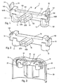
- Figure 1 shows both the external and internal structure of a dispensing head according to a non-limiting embodiment of the invention.
- Figure 1 corresponds to the state of the dispensing head at the outlet of the mold.
- the dispensing head can advantageously be made by plastic molding, as is currently the case for the constituent parts of the fluid dispensers.
- the dispensing head of the invention can also be made other than by molding a plastic material.
- the dispensing head comprises two connecting sleeves 11 and 12 which extend parallel to each other with a certain distance which corresponds to the spacing between the two hollow actuating rods of two dispensing members ( pump or valve) which are mounted on respective fluid tanks.
- the free upper ends of the hollow actuating rods are substantially located at the same level, so that the connecting sleeves 11 and 12 are also located at the same height relative to each other.
- These connecting sleeves 11 and 12 each internally define an inlet duct 110, 120 which is preferably rectilinear and even circular cylindrical.
- the actuating rods are connected to the sleeves 11 and 12 by introducing their upper ends into the inlet ducts 110 and 120.
- the dispensing head further comprises a cross member 10 which connects the two sleeves 11 and 12 between them.
- This crosspiece 10 is here perfectly rectilinear, but it can also be bent or curved.
- the connecting sleeves 11 and 12 connect the cross member 10 near each opposite end of the cross member 10, at its lower side. It can be said that the cross member 10 is supported by the two sleeves 11 and 12 at both ends.
- the crosspiece 10 internally defines two connecting ducts 101, 102, advantageously rectilinear, which communicate directly respectively with the inlet ducts 110 and 120 of the sleeves 11 and 12. It should be noted that the connecting ducts 101 and 102 do not extend not in the extension of the inlet ducts 110 and 120, but instead extend transversely or even perpendicularly.
- the dispensing head also comprises a dispensing nozzle 13 which connects the cross member 10, advantageously in the middle thereof. In the case where the cross member 10 is bent, the dispensing nozzle 13 connects the cross member 10 at the elbow formed by the cross member.
- the dispensing nozzle 13 internally defines two outlet ducts 131 and 132 which are advantageously rectilinear. These outlet ducts communicate with one of their ends respectively with the connecting ducts 101 and 102 and define at their other free end two dispensing orifices 1310 and 1320.
- the ducts 131 and 132 do not extend not in the extension of the connecting conduits 101 and 102, but instead extend transversely and even perpendicularly.
- the inlet duct 110 communicates with the outlet duct 131 via the connecting duct 101.
- the duct the inlet duct 120 communicates with the outlet duct 132 via the connecting duct 102.
- the inlet ducts extend vertically, while the connecting and outlet ducts extend horizontally but in different directions, advantageously perpendicular. It can thus be noted that the connecting ducts 101 and 102 extend transversely both with respect to the inlet ducts 110 and 120 and to the outlet ducts 131, 132. As a result, the connecting ducts 101 and 102 do not would in practice be very difficult to access and practically not moldable.
- each connecting duct 101, 102 is provided with an access opening 1010, 1020.
- These access openings are preferably located at one end of the connecting ducts so that they allow a rectilinear access over the entire length of the conduit.
- these access openings 1010 and 1020 are located at the opposite longitudinal ends of the cross member 10, that is to say adjacent to the connection sleeve 12.
- These openings 1010 and 1020 are extend in a vertical plane while the passage for communicating between the inlet ducts 110, 120 and the connecting ducts 101, 102 extend in a horizontal plane. It is easy to understand that it is easy to introduce a pin inside the connecting ducts 101, 102 through their respective access openings 1010, 1020.
- the molding pin of the connecting conduit 102 can thus come into contact with the free end of the molding pin forming the inlet duct 120 to create the communication passage between the inlet duct and the connecting duct 102.
- the molding pin of the connecting duct 102 comes into contact at its free end with the free end the molding pin of the outlet duct 132 to thereby create a communication passage between the connecting duct and the outlet duct 132.
- these access openings 1010, 1020 are closed hermetically with the aid of closure elements which thus fulfill a waterproof cap function.
- these closure elements can be made integrally with the rest of the dispensing head.
- the closure elements are in the form of flaps 14, 15 which are articulated, preferably by pivoting on the remainder of the head.
- the flaps 14, 15 may advantageously pivot about a rectilinear axis 142, 152 made by bridges of flexible material which make the connection between the flaps and the rest of the head.
- the flaps 14 and 15 are connected to the cross member 10 at its edges of opposite upper ends located just above the access openings 1010, 1020.
- the pivoting flaps 14, 15 advantageously form each a sealing pin 141, 151 adapted to be engaged in force within the respective openings 1010, 1020.
- the articulation of the flaps made by pivoting about a fixed axis allows to bring the nipples 141 and 151 accurately and centered with respect to the access openings.
- the dispensing head is represented in a configuration corresponding to that at the exit of the mold, that is to say with the flaps 14 and 15 extending vertically above the cross member 10.
- the flaps 14 and 15 have been folded by pivoting about their respective axes 142, 152 so that they are now located in the extension of the opposite ends of the crosspiece 10.
- the sealing nipples 141 and 151 are then engaged from sealingly in the openings 1010, 1020 which are now hermetically sealed.
- the dispensing head as shown in Figure 2 is then operational.
- the dispensing head according to the invention can be made in one piece, that is to say integrating both the connecting sleeves 11 and 12, the crosspiece 10, the end piece 13 as well as the two flaps.
- the form of connection of the closure elements 14 and 15 to the remainder of the head here in the form of an advantageously swivel joint is only one advantageous but not unique embodiment.
- the dispensing head shown in the drawings and described above comprises two connecting ducts 101 and 102 each provided with an opening 1010, 1020.
- the dispensing nozzle 13 here comprises two outlet ducts 131 and 132. It is however possible to make a dispensing head having only one outlet duct, and therefore a single dispensing orifice.
- the two connecting ducts 101 and 102 can be connected together so as to constitute only one connecting duct which extends over the entire length of the crossbar 10. It is then no longer necessary to provide two access openings, since only one is sufficient to engage the molding pin which would then intercept the two inlet ducts 110 and 120 and the single outlet duct.
- the access openings no longer in the form of an opening located at one end of the connecting duct 102, but in the form of a cover which allows access over the entire length of the connecting pipe.
- the cross member 10 is provided with two pivoting covers situated on its upper side or on its rear face so that it is possible to mold with a single pin the duct 102 and the inlet duct 120 or the duct.
- the crosspiece 10 can be equipped with a single longitudinal cover which extends substantially over its entire length so that the the two inlet ducts 110 and 120 and the single connection duct can be molded with a single pin.
- FIG. 3 represents the dispensing head of FIGS. 1 and 2 integrated inside a pusher 2 intended to cover the dispensing members (pump and valve of the "duo" dispenser).
- the pusher 2 comprises a substantially cylindrical peripheral skirt 20 and an upper wall forming a bearing surface 21 on which can be pressed with one or more finger (s). It should be noted that this bearing surface 21 is located substantially in the center or in the middle of the crosspiece 10 at the dispensing nozzle 13.
- the pusher 2 forms an inner housing adapted to receive the dispensing head 1.
- this internal housing comprises two locking flanges 22 intended to come into bearing contact against the shutters 14 and 15 so as to block them in the position of Figure 2, that is to say with their nipples tightly engaged in the access openings.
- it is also possible to guarantee the tightness of the head at the flaps by conventional sealing techniques such as gluing or welding.
Landscapes
- Chemical & Material Sciences (AREA)
- Dispersion Chemistry (AREA)
- Engineering & Computer Science (AREA)
- Mechanical Engineering (AREA)
- Containers And Packaging Bodies Having A Special Means To Remove Contents (AREA)
- Closures For Containers (AREA)
- Processing And Handling Of Plastics And Other Materials For Molding In General (AREA)
- Orthopedics, Nursing, And Contraception (AREA)
Claims (7)
- Abgabekopf (1) zur Anbringung an zwei parallelen hohlen Betätigungsstangen, wobei der Kopf einstückig aus Kunststoffmaterial hergestellt ist und aufweist:- zwei parallele Verbindungsmuffen (11, 12) zum jeweiligen Eingriff mit den Betätigungsstangen, wobei die Muffen jeweilige Eingangsleitungen (110, 120) festlegen,- einen Abgabeansatz (13), der zumindest eine Ausgangsleitung festlegt, welche in zumindest eine Abgabeöffnung (1310, 1320) ausmündet, und- eine Traverse (10), welche die Muffen mit dem Ansatz verbindet, wobei die Traverse zumindest eine Verbindungsleitung (101, 102) festlegt, welche die Einlassleitungen (110, 112) mit der bzw. den Auslassleitungen (1310, 1320) verbindet, wobei die zumindest eine Verbindungsleitung sich sowohl unter Bezug auf die Muffen wie auf den bzw. die Auslassleitungen transversal erstreckt, wobei die zumindest eine Verbindungsleitung (101, 102) eine Zugangsöffnung (1010, 1020) umfasst, welche durch ein Verschlusselement (14, 15) dicht verschlossen ist,
wobei das Verschlusselement (14, 15) mit dem Rest (10, 11, 12, 13) des Kopfes einstückig ausgebildet ist, dadurch gekennzeichnet, dass die Zugangsöffnung (1010, 1020) an einem axialen Ende der Verbindungsleitung (101, 102) derart angeordnet, dass durch diese Öffnung eine Spindel einführbar und bis zum anderen Ende der Leitung eingedrückt ist, in dem sie nacheinander vor einer Einlassleitung und einer Auslassleitung hindurch tritt. - Abgabekopf nach Anspruch 1, wobei das Verschlusselement (14, 15) an den Kopf angelenkt ist.
- Abgabekopf nach Anspruch 2, wobei das Verschlusselement (14, 15) um eine Achse (142, 152) zwischen einer offenen Stellung und einer Verschlussstellung verschwenkbar ist.
- Abgabekopf nach Anspruch 3, wobei das Verschlusselement in Form einer verschwenkbaren Klappe (14, 15) vorliegt, die mit dem Rest des Kopfes durch eine Brücke (142, 152) nachgiebig verbunden ist.
- Abgabekopf nach Anspruch 4, wobei die Klappe (14, 15) einen Dichtungsansatz (141, 151) zum Einpassen in die Zugangöffnung (1010, 1020) unter Kraftausübung umfasst.
- Abgabekopf nach einem der vorangehenden Ansprüche, aufweisend zwei Ausgangsleitungen (1310, 1320) und zwei Verbindungsleitungen (101, 102), die jede Eingangsleitung (110, 120) mit einer Ausgangsleitung (1310, 1320) verbindet, wobei jede Verbindungsleitung mit einer Zugangsöffnung (1010, 1020) und einem Verschlusselement (14, 15) versehen ist, das an den gegenüberliegenden Enden der Traverse (10) angeordnet ist.
- Stößel (2), aufweisend einen Abgabekopf (1) nach einem der vorangehenden Ansprüche, wobei der Stößel ein Aufnahmelager für den Kopf festlegt, wobei das Lager Blockiermittel (22) für das Versschlusselement in der Zugangsöffnung umfasst.
Applications Claiming Priority (3)
| Application Number | Priority Date | Filing Date | Title |
|---|---|---|---|
| FR0204812A FR2838357B1 (fr) | 2002-04-16 | 2002-04-16 | Tete de distribution et poussoir incorporant une telle tete |
| FR0204812 | 2002-04-16 | ||
| PCT/FR2003/001184 WO2003086652A1 (fr) | 2002-04-16 | 2003-04-14 | Tete de distribution et poussoir incorporant une telle tete |
Publications (2)
| Publication Number | Publication Date |
|---|---|
| EP1497040A1 EP1497040A1 (de) | 2005-01-19 |
| EP1497040B1 true EP1497040B1 (de) | 2006-02-15 |
Family
ID=28459909
Family Applications (1)
| Application Number | Title | Priority Date | Filing Date |
|---|---|---|---|
| EP03740606A Expired - Lifetime EP1497040B1 (de) | 2002-04-16 | 2003-04-14 | Abgabekopf und betätigungskopf mit einem solchen abgabekopf |
Country Status (9)
| Country | Link |
|---|---|
| US (1) | US7290681B2 (de) |
| EP (1) | EP1497040B1 (de) |
| CN (1) | CN1655878A (de) |
| AU (1) | AU2003262158A1 (de) |
| BR (1) | BR0309267A (de) |
| DE (1) | DE60303601T2 (de) |
| ES (1) | ES2257681T3 (de) |
| FR (1) | FR2838357B1 (de) |
| WO (1) | WO2003086652A1 (de) |
Families Citing this family (9)
| Publication number | Priority date | Publication date | Assignee | Title |
|---|---|---|---|---|
| WO2006012600A1 (en) * | 2004-07-23 | 2006-02-02 | The Dial Corporation | Multiple dispenser container |
| JP5789405B2 (ja) * | 2011-04-25 | 2015-10-07 | 株式会社吉野工業所 | 二連式容器 |
| DE202012004644U1 (de) * | 2012-05-11 | 2013-05-13 | Gerhard Brugger | Sprühspender fûr mehrere Komponenten |
| JP5901565B2 (ja) * | 2013-04-03 | 2016-04-13 | 東洋エアゾール工業株式会社 | エアゾール容器用吐出具 |
| FR3040639B1 (fr) * | 2015-09-09 | 2020-01-03 | Aptar France Sas | Distributeur duo |
| CN108463416B (zh) * | 2016-01-18 | 2020-01-21 | 东洋喷雾工业株式会社 | 喷雾容器用固定盘 |
| US10974265B1 (en) * | 2018-07-22 | 2021-04-13 | Paul Sung Ventresca LLC | Spray device with interchangeable cartridges and methods of use |
| JP7315727B2 (ja) * | 2019-07-09 | 2023-07-26 | ザ プロクター アンド ギャンブル カンパニー | 多組成物製品ディスペンサ |
| CN114080359B (zh) | 2019-07-09 | 2023-07-04 | 宝洁公司 | 多组合物产品分配器 |
Family Cites Families (5)
| Publication number | Priority date | Publication date | Assignee | Title |
|---|---|---|---|---|
| FR2603558B1 (fr) * | 1986-09-04 | 1988-11-18 | Oreal | Tete de distribution d'un produit pateux resultant du melange de deux composants stockes separement et ensemble de conditionnement dote d'une telle tete de distribution |
| JPH10211971A (ja) * | 1997-01-28 | 1998-08-11 | Toyo Seikan Kaisha Ltd | 多液吐出容器 |
| JP3751125B2 (ja) * | 1997-08-08 | 2006-03-01 | ホーユー株式会社 | 2剤吐出容器 |
| EP1075325B1 (de) * | 1999-02-26 | 2003-11-05 | Wella Aktiengesellschaft | Vorrichtung zum mischen, aufschäumen und ausgeben von flüssigkeiten aus separaten druckgasbehältern |
| FR2815616B1 (fr) * | 2000-10-20 | 2003-01-24 | Oreal | Ensemble de distribution destine a la distribution extemporanee de deux produits |
-
2002
- 2002-04-16 FR FR0204812A patent/FR2838357B1/fr not_active Expired - Lifetime
-
2003
- 2003-04-14 AU AU2003262158A patent/AU2003262158A1/en not_active Abandoned
- 2003-04-14 ES ES03740606T patent/ES2257681T3/es not_active Expired - Lifetime
- 2003-04-14 WO PCT/FR2003/001184 patent/WO2003086652A1/fr not_active Ceased
- 2003-04-14 US US10/511,093 patent/US7290681B2/en not_active Expired - Fee Related
- 2003-04-14 CN CN03811942.0A patent/CN1655878A/zh active Pending
- 2003-04-14 BR BR0309267-4A patent/BR0309267A/pt not_active Application Discontinuation
- 2003-04-14 EP EP03740606A patent/EP1497040B1/de not_active Expired - Lifetime
- 2003-04-14 DE DE60303601T patent/DE60303601T2/de not_active Expired - Fee Related
Also Published As
| Publication number | Publication date |
|---|---|
| AU2003262158A1 (en) | 2003-10-27 |
| BR0309267A (pt) | 2005-02-22 |
| DE60303601D1 (de) | 2006-04-20 |
| WO2003086652A1 (fr) | 2003-10-23 |
| FR2838357B1 (fr) | 2005-03-25 |
| CN1655878A (zh) | 2005-08-17 |
| US20050127094A1 (en) | 2005-06-16 |
| US7290681B2 (en) | 2007-11-06 |
| FR2838357A1 (fr) | 2003-10-17 |
| DE60303601T2 (de) | 2006-11-02 |
| EP1497040A1 (de) | 2005-01-19 |
| ES2257681T3 (es) | 2006-08-01 |
Similar Documents
| Publication | Publication Date | Title |
|---|---|---|
| EP1202918B1 (de) | Spender mit gelenkigem spenderkopf | |
| EP1642846B1 (de) | Vorrichtung zur gleichzeitigen Abgabe zweier Produkte | |
| EP1551560A1 (de) | Vorrichtung zur medienabgabe | |
| EP2579991B1 (de) | Abgabekopf für ein fluid | |
| CA2217400A1 (fr) | Distributeur pour le soutirage d'un produit fluide contenu dans un recipient | |
| EP3146864A1 (de) | Ausgabe- sowie auftrags-kopf | |
| EP1991476B1 (de) | Abgabedüse für eine vorrichtung zur abgabe eines fluidprodukts | |
| EP1497040A1 (de) | Abgabekopf und betätigungskopf mit einem solchen abgabekopf | |
| EP3687923B1 (de) | Stem für zweiwegeventil | |
| EP2608692B1 (de) | Spenderkopf für ein flüssiges produkt | |
| EP3980350B1 (de) | Ventil für druckbehälter | |
| FR2906981A1 (fr) | Embout de distribution pour dispositif de conditionnement et de distribution d'un produit cosmetique, et dispositif associe | |
| FR2842791A1 (fr) | Reservoir de produit fluide et dispositif de distribution de produit fluide comportant un tel reservoir | |
| FR2785222A1 (fr) | Procede de fabrication d'un obturateur, poussoir et tete de distribution incorporant un tel obturateur | |
| WO2002068290A1 (fr) | Distributeur de produit fluide a poche souple et procede de fabrication d'une telle poche souple | |
| EP1688368B1 (de) | Sprühkopf | |
| WO2005032972A2 (fr) | Tete de distribution de produit fluide et procede de fabrication d'une telle tete. | |
| FR2876676A1 (fr) | Capuchon de poussoir, poussoir et organe de distribution a poussoir pourvus d'un tel capuchon et procede de montage d'un tel capuchon sur un poussoir. | |
| WO2025083370A1 (fr) | Distributeur de produit fluide | |
| WO2004076074A1 (fr) | Tete de distribution | |
| FR2855159A1 (fr) | Tete de distribution montee ou faisant partie d'un organe de distribution de produit fluide | |
| WO2008104655A2 (fr) | Distributeur de produit fluide | |
| WO2014139892A1 (fr) | Contenant économique pour un produit sous forme liquide | |
| FR2728871A1 (fr) | Bouchon a obturateur deplacable axialement, procede de realisation d'un tel bouchon et ensemble comportant un tel bouchon |
Legal Events
| Date | Code | Title | Description |
|---|---|---|---|
| PUAI | Public reference made under article 153(3) epc to a published international application that has entered the european phase |
Free format text: ORIGINAL CODE: 0009012 |
|
| 17P | Request for examination filed |
Effective date: 20041110 |
|
| AK | Designated contracting states |
Kind code of ref document: A1 Designated state(s): AT BE BG CH CY CZ DE DK EE ES FI FR GB GR HU IE IT LI LU MC NL PT RO SE SI SK TR |
|
| AX | Request for extension of the european patent |
Extension state: AL LT LV MK |
|
| 17Q | First examination report despatched |
Effective date: 20050302 |
|
| GRAP | Despatch of communication of intention to grant a patent |
Free format text: ORIGINAL CODE: EPIDOSNIGR1 |
|
| GRAS | Grant fee paid |
Free format text: ORIGINAL CODE: EPIDOSNIGR3 |
|
| GRAA | (expected) grant |
Free format text: ORIGINAL CODE: 0009210 |
|
| AK | Designated contracting states |
Kind code of ref document: B1 Designated state(s): DE ES FR GB IT |
|
| REG | Reference to a national code |
Ref country code: GB Ref legal event code: FG4D Free format text: NOT ENGLISH |
|
| REF | Corresponds to: |
Ref document number: 60303601 Country of ref document: DE Date of ref document: 20060420 Kind code of ref document: P |
|
| GBT | Gb: translation of ep patent filed (gb section 77(6)(a)/1977) |
Effective date: 20060502 |
|
| REG | Reference to a national code |
Ref country code: ES Ref legal event code: FG2A Ref document number: 2257681 Country of ref document: ES Kind code of ref document: T3 |
|
| PLBE | No opposition filed within time limit |
Free format text: ORIGINAL CODE: 0009261 |
|
| STAA | Information on the status of an ep patent application or granted ep patent |
Free format text: STATUS: NO OPPOSITION FILED WITHIN TIME LIMIT |
|
| 26N | No opposition filed |
Effective date: 20061116 |
|
| PGFP | Annual fee paid to national office [announced via postgrant information from national office to epo] |
Ref country code: ES Payment date: 20090422 Year of fee payment: 7 |
|
| PGFP | Annual fee paid to national office [announced via postgrant information from national office to epo] |
Ref country code: DE Payment date: 20090414 Year of fee payment: 7 Ref country code: IT Payment date: 20090423 Year of fee payment: 7 |
|
| PGFP | Annual fee paid to national office [announced via postgrant information from national office to epo] |
Ref country code: GB Payment date: 20090407 Year of fee payment: 7 |
|
| GBPC | Gb: european patent ceased through non-payment of renewal fee |
Effective date: 20100414 |
|
| PG25 | Lapsed in a contracting state [announced via postgrant information from national office to epo] |
Ref country code: DE Free format text: LAPSE BECAUSE OF NON-PAYMENT OF DUE FEES Effective date: 20101103 |
|
| PG25 | Lapsed in a contracting state [announced via postgrant information from national office to epo] |
Ref country code: GB Free format text: LAPSE BECAUSE OF NON-PAYMENT OF DUE FEES Effective date: 20100414 Ref country code: IT Free format text: LAPSE BECAUSE OF NON-PAYMENT OF DUE FEES Effective date: 20100414 |
|
| REG | Reference to a national code |
Ref country code: ES Ref legal event code: FD2A Effective date: 20110712 |
|
| PG25 | Lapsed in a contracting state [announced via postgrant information from national office to epo] |
Ref country code: ES Free format text: LAPSE BECAUSE OF NON-PAYMENT OF DUE FEES Effective date: 20110630 |
|
| PG25 | Lapsed in a contracting state [announced via postgrant information from national office to epo] |
Ref country code: ES Free format text: LAPSE BECAUSE OF NON-PAYMENT OF DUE FEES Effective date: 20100415 |
|
| REG | Reference to a national code |
Ref country code: DE Ref legal event code: R082 Ref document number: 60303601 Country of ref document: DE Representative=s name: DE ANNA, PIER LUIGI, DR.-ING., DE |
|
| REG | Reference to a national code |
Ref country code: FR Ref legal event code: CD Owner name: APTAR FRANCE SAS, FR Effective date: 20130103 Ref country code: FR Ref legal event code: TP Owner name: APTAR FRANCE SAS, FR Effective date: 20130103 |
|
| REG | Reference to a national code |
Ref country code: FR Ref legal event code: PLFP Year of fee payment: 13 |
|
| REG | Reference to a national code |
Ref country code: FR Ref legal event code: PLFP Year of fee payment: 14 |
|
| REG | Reference to a national code |
Ref country code: FR Ref legal event code: PLFP Year of fee payment: 15 |
|
| REG | Reference to a national code |
Ref country code: FR Ref legal event code: PLFP Year of fee payment: 16 |
|
| PGFP | Annual fee paid to national office [announced via postgrant information from national office to epo] |
Ref country code: FR Payment date: 20180424 Year of fee payment: 16 |
|
| PG25 | Lapsed in a contracting state [announced via postgrant information from national office to epo] |
Ref country code: FR Free format text: LAPSE BECAUSE OF NON-PAYMENT OF DUE FEES Effective date: 20190430 |