EP1497571B1 - Procede et enrouleur permettant de raccourcir et eventuellement de mettre sous tension des elements tendeurs oblongs - Google Patents
Procede et enrouleur permettant de raccourcir et eventuellement de mettre sous tension des elements tendeurs oblongs Download PDFInfo
- Publication number
- EP1497571B1 EP1497571B1 EP02807250A EP02807250A EP1497571B1 EP 1497571 B1 EP1497571 B1 EP 1497571B1 EP 02807250 A EP02807250 A EP 02807250A EP 02807250 A EP02807250 A EP 02807250A EP 1497571 B1 EP1497571 B1 EP 1497571B1
- Authority
- EP
- European Patent Office
- Prior art keywords
- shank
- cord
- spool
- formation
- length
- Prior art date
- Legal status (The legal status is an assumption and is not a legal conclusion. Google has not performed a legal analysis and makes no representation as to the accuracy of the status listed.)
- Expired - Lifetime
Links
- 238000004904 shortening Methods 0.000 title claims abstract description 20
- 238000000034 method Methods 0.000 title claims abstract description 7
- 230000015572 biosynthetic process Effects 0.000 claims abstract description 84
- 238000005755 formation reaction Methods 0.000 claims description 79
- 239000002184 metal Substances 0.000 claims description 5
- 238000004804 winding Methods 0.000 claims description 4
- 239000000725 suspension Substances 0.000 claims description 3
- 230000000694 effects Effects 0.000 description 3
- 238000009434 installation Methods 0.000 description 3
- 238000002347 injection Methods 0.000 description 2
- 239000007924 injection Substances 0.000 description 2
- 229910000639 Spring steel Inorganic materials 0.000 description 1
- 229910000831 Steel Inorganic materials 0.000 description 1
- 239000000463 material Substances 0.000 description 1
- 239000002991 molded plastic Substances 0.000 description 1
- 239000004033 plastic Substances 0.000 description 1
- 229920003023 plastic Polymers 0.000 description 1
- 239000010959 steel Substances 0.000 description 1
Images



Classifications
-
- F—MECHANICAL ENGINEERING; LIGHTING; HEATING; WEAPONS; BLASTING
- F16—ENGINEERING ELEMENTS AND UNITS; GENERAL MEASURES FOR PRODUCING AND MAINTAINING EFFECTIVE FUNCTIONING OF MACHINES OR INSTALLATIONS; THERMAL INSULATION IN GENERAL
- F16G—BELTS, CABLES, OR ROPES, PREDOMINANTLY USED FOR DRIVING PURPOSES; CHAINS; FITTINGS PREDOMINANTLY USED THEREFOR
- F16G11/00—Means for fastening cables or ropes to one another or to other objects; Caps or sleeves for fixing on cables or ropes
- F16G11/12—Connections or attachments, e.g. turnbuckles, adapted for straining of cables, ropes, or wire
-
- A—HUMAN NECESSITIES
- A47—FURNITURE; DOMESTIC ARTICLES OR APPLIANCES; COFFEE MILLS; SPICE MILLS; SUCTION CLEANERS IN GENERAL
- A47G—HOUSEHOLD OR TABLE EQUIPMENT
- A47G1/00—Mirrors; Picture frames or the like, e.g. provided with heating, lighting or ventilating means
- A47G1/16—Devices for hanging or supporting pictures, mirrors, or the like
- A47G1/18—Picture loops or the like
-
- Y—GENERAL TAGGING OF NEW TECHNOLOGICAL DEVELOPMENTS; GENERAL TAGGING OF CROSS-SECTIONAL TECHNOLOGIES SPANNING OVER SEVERAL SECTIONS OF THE IPC; TECHNICAL SUBJECTS COVERED BY FORMER USPC CROSS-REFERENCE ART COLLECTIONS [XRACs] AND DIGESTS
- Y10—TECHNICAL SUBJECTS COVERED BY FORMER USPC
- Y10S—TECHNICAL SUBJECTS COVERED BY FORMER USPC CROSS-REFERENCE ART COLLECTIONS [XRACs] AND DIGESTS
- Y10S24/00—Buckles, buttons, clasps
- Y10S24/909—Winders for flexible material
-
- Y—GENERAL TAGGING OF NEW TECHNOLOGICAL DEVELOPMENTS; GENERAL TAGGING OF CROSS-SECTIONAL TECHNOLOGIES SPANNING OVER SEVERAL SECTIONS OF THE IPC; TECHNICAL SUBJECTS COVERED BY FORMER USPC CROSS-REFERENCE ART COLLECTIONS [XRACs] AND DIGESTS
- Y10—TECHNICAL SUBJECTS COVERED BY FORMER USPC
- Y10T—TECHNICAL SUBJECTS COVERED BY FORMER US CLASSIFICATION
- Y10T24/00—Buckles, buttons, clasps, etc.
- Y10T24/14—Bale and package ties, hose clamps
- Y10T24/1412—Bale and package ties, hose clamps with tighteners
- Y10T24/1416—Winder
Definitions
- This invention relates to a method and spool for shortening the effective length of elongate flexible tension members whilst optionally tensioning them and, more particularly, but not exclusively, tension members that may be in the form of multistrand wires, or cords used for suspending pictures and other decorative items from a suspension point, typically a hook or nail fixed to a wall; as well as numerous other elongate flexible members held in tension such as, without restriction, guy ropes, clothes lines, communications cables such as aerial telephone wires and powerlines and strands of fence wires.
- the invention relates to a spool that can be used for shortening wires or cords suspending pictures with a view to adjusting the height of the picture relative to a hook or nail fixed to a wall against which it is suspended.
- the main objective is to apply tension to the elongate flexible tension member all to carry out a lifting operation of an object suspended by the flexible tension member.
- cord will be used throughout this specification to include stranded or other wires, ropes, clotheslines etc as well as elongate tension members in general as the context will indicate.
- the scope of this invention is therefore not to be interpreted as being limited in any way by use of the expression "cord” in the definitive statements and claims hereof.
- a second type of which US patents 696,510; 769,695; and 862,011 are examples seeks to wind at least one end portion of the picture cord onto a reel that is arrested in the required position by means of a ratchet of some type or another.
- the axis of the reel is at generally right angles to the picture cord, in the normal way.
- a third type seeks to create a deviation to the natural straight condition of a portion of the length of the cord so as to shorten the effective length thereof.
- US patents 4,566,665 and 3,251,569 and international patent application WO 9616580 achieve this using a screw thread and nut in combination with a pair of spaced guides so that the cord follows a generally U-shaped path. The depth of the U varies according to the position of the nut along the length of the screw thread to vary the effective length of the cord.
- US patent 5,695,147 is also of this general type and has a guide rotatable in unison with a ratchet for creating a variable degree of zigzag in the length of the picture cord to shorten it to different extents.
- EP 1088502 Yet another different type is set forth in European patent application number EP 1088502 in which at least one end region of the cord is engaged by a gripping dog of a fitting associated with the picture frame.
- the dog can be engaged with the cord at any position along its length to vary the effective length of the cord.
- tensioners employ spaced formations adapted to take up a predetermined amount of cord length that may be selected from a plurality of different amounts and some of such tensioners are described in US patents 5,655,267; 5,519,921; 5,383,256; 3,815,180; 3,711,901; 1,855,049; 550,970; and 432,429.
- an object of this invention to provide a method and spool for shortening the effective length of a cord whilst optionally tensioning same, whereby at least some of the disadvantages associated with prior art devices referred to above may be obviated, at least some extent.
- a spool for shortening the length of a cord and optionally tensioning it at the same time, the spool comprising a reel formation in the form of an elongate generally straight shank around which cord can be wound to shorten its effective length, the shank having a transverse retainer formation at each of its ends for operatively preventing cord wound onto the reel from unwinding therefrom, a keeper formation at one end of the shank for cooperation with a cord to maintain said end in association with the cord whilst the shank is rotated to wind cord onto the shank by rotation thereof and a torque transmitting formation whereby the reel can be rotated about its own axis either directly by hand or indirectly utilizing a tool, the spool being characterized in that the transverse retainer formations are adapted operatively to prevent unravelling off the shank of cord wound around the elongate shank at least whilst the cord is held under tension and the axis of the shank extends in the same general direction
- transverse retainer formation at said one end of the shank to form also the keeper formation; for the retainer formation at the other end of the shank to form also the torque transmitting formation; for the length of the shank to be from about 10 to about 50 times the diameter thereof, preferably from 15 to 40 times the diameter; and for additional holding means to be provided for releasably engaging a cooperant cord to prevent unravelling thereof off the shank under conditions in which tension is removed from the cord.
- the spool is formed from a suitable gauge of wire or rod that is bent to form a generally straight shank in the middle; a combination retainer formation and keeper formation at one end; and a combination retainer formation and torque transmitting formation at the other end.
- the wire or rod can also be bent and optionally stamped to form any additional holding means for releasable engagement with a cooperating cord.
- any additional holding means could be formed as part of a separate element for attachment to a handle of the spool.
- no additional holding means is required, and in the simplest forms of the invention such an expedient is omitted in order to save cost.
- such additional holding means is only required to prevent unravelling of any cord wound onto it when tension is substantially entirely removed from the cord as tension in the cord substantially locks the spool against unravelling of cord therefrom.
- the torque transmitting formation preferably be a manually operable handle, and in this regard a spool for shortening picture cords to thereby adjust the height of an associated picture is of particular note, such formation is simply formed integral with the spool generally as a continuation of a length of bent wire or rod.
- the handle could be wing shaped to project outwardly on diametrically opposite sides of the shank and the handle serves also as the retainer formation.
- the combined keeper and retainer formation at the opposite end can be defined by a portion of wire bent to form a hook or eye orientated roughly in a plane at generally right angles to the axis of the shank.
- the torque transmitting formation is adapted for cooperation with a separate manually operable tool, typically in the form of a crank, for applying a rotational force to the spool by cooperation with the torque transmitting formation.
- the tool will preferably have engagement means configured to hold the spool and a cooperant part of the manually operable tool in substantial axial alignment during cooperative use of the tool on the spool for the purpose of rotating it.
- the spool preferably has a generally axially extending axle for cooperation with a bore or socket in a cooperant part of said manually operable tool in order to align said part and the spool approximately axially during cooperant use thereof.
- the keeper means is a slot extending axially inwards from the end of the shank remote from the handle.
- a method of shortening a cord comprising the steps of associating the keeper formation of a spool as defined above with the cord; rotating the shank generally about its own axis by means of the torque transmitting formation with the shank extending transverse to the cord so as to wind cord around the shank to a required extent; and releasing the torque transmitting formation such that the shank extends in the same general direction as the cord and the transverse retainer formations at each end serve to prevent unravelling of the cord from the shank.
- the spool to be manipulated such that the shank extends at an incline to the cord, at least during initial rotation of the shank and to initiate winding of the cord around the shank; for the cord in the case that a plurality of revolutions of the shank are required to shorten the length thereof adequately to be predominantly wound on the shank near the end thereof having the keeper formation, this being effected by manipulating the angle at which the shank extends transverse to the general length of the cord, followed by a decrease in the angle at which the shank extends relative to the cord so that a final revolution or part revolution of the cord spirals along a substantial portion of the length of the shank; and, in the case that additional holding means are provided, to engage such holding means with the cord to releasably attach same to the spool.
- the invention also provides a picture having a cord for suspending it from a suspension point and a spool as defined above associated with the cord.
- a spool is made for the particular purpose of shortening picture cords and is formed from bent wire.
- the diameter of the wire is chosen according to requirements and it is envisaged that spools according to the invention may be made in different sizes for application to different size ranges of pictures and, more particularly, different thicknesses of cords.
- the spool is aimed at a rather middle of the range of thicknesses of cord and for this purpose a steel wire of about 2.5 to 3 mm (0.1 to 0.125 inch) in diameter has been found to operate satisfactorily as the shank.
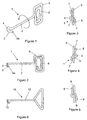
- the spool has a straight shank (2) the length of which can be chosen according to requirements and which is not be too short so as to make it difficult to use.
- a length of the shank of about 30 to 55 mm (12 to 22 inches) has been found to be effective and, a current model has a length of 50 mm (2 inches) with a diameter of 2.5 mm (0.1 inch). These dimensions translate to a range of length of shank of from 10 to 22 times the diameter of the wire. It will be understood that a longer shank will enable a more accurate shortening of the wire or cord to be possible although it will be correspondingly more expensive. Doubtless, experience will assist in enabling a substantially ideal length to be determined bearing in mind both cost and efficacy.
- the wire at one end of the shank is bent generally radially outwards and thence into a generally radially inwardly projecting U-shaped or hook formation as indicated by numeral (3).
- the web (4) of the U-shape is thus offset from the axis of the shank.
- the U-shaped formation forms a combination of both the transverse retainer formation of one end of the shank and the keeper formation in this embodiment of the invention. It has been found that operation of the spool is facilitated if the free end (3a) of the U-shape is positioned radially offset from the shank and opposite the shank a short distance towards the opposite end thereof as shown clearly in Figure 2.
- the wire at the opposite end of the shank is bent radially outwards and thence into a diametrically extending rectangular handle (5) whereby the shank can be manually rotated about its own axis.
- the diametrical dimension of the handle can be, for example, of the order of 40 to 45 mm so as to provide a substantial mechanical advantage for winding a wire or cord onto the shank when a major part of the weight of a picture is supported by the wire or cord.
- the wire is further bent to form an inner rectangular convolution (6) that is contained in a plane angularly offset from that of the handle to provide convergent gaps (7) (see Figures 3 and 4) that define additional holding means of the nature defined above.
- the cord can be wedged releasably into these gaps to hold it in association with the spool, for example when a picture is removed from its hanging position and tension in the cord is released.
- the inner rectangular convolution could be subjected to a stamping operation in order to offset two wings (8) of the handle and to form convergent gaps (9) having a smaller angle that conforms is more to a locking wedge configuration.
- Figure 6 illustrates a simpler embodiment of the invention, generally indicated by numeral (10), that is similar to the one illustrated in Figures 1 to 4 but with the additional holding means (the inner convolution) totally omitted and the shape of the handle (11) accordingly varied to a roughly squat triangular configuration.
- the spool of this embodiment thus comprises the handle (11) at one end of a straight shank (12) and a generally radially extending U-shaped formation (13) at the opposite end, as described with reference to Figures 1 to 4.
- the spool described with reference to Figure 6 may be used on a cord (14) that is installed in the usual way on a picture (15) by attaching the two ends (16) of the cord to fasteners (17) fixed to the picture frame (18). It will be understood that by shortening the effective length of the cord between the fasteners the height at which the picture hangs will be adjusted.
- the one side of the picture can simply be pulled away slightly from the wall and the spool manipulated so that the cord (14) is located in the U-shaped formation (13) with the shank (12) extending at an incline to the cord as shown in Figure 8.
- Rotation of the shank using the handle (11) in the appropriate direction, in this case in clockwise direction when viewed from the handle end of the spool, will cause the cord to become wound around the shank.
- the cord (14) can be engaged in the gaps (7) on either side of the handle as illustrated in Figures 12 and 13.
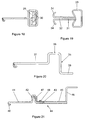
- a spool generally indicated by numeral (22) is made of injection moulded plastics material and has a flat configuration with a shank (23) that has a slot (24) entering from one end and an integral handle (25) at the opposite end.
- a laterally extending retainer formation (26) extends arcuately outwards from each side of the slotted end of the shank and the opposing edges (27) of the handle are arcuately shaped complimentarily. The arcuate shapes assist in guiding the wire or cord into engagement with the relevant component when the spool is moved to its orientation in which the shank extends in the same general direction as a cord on which it is used.
- a pair of integral clips (28) are formed in the handle with one being accessible from each side of the handle. These clips are shaped such that a cord can be engaged underneath them to retain the cord releasably in association with the handle. The clips thus serve as the additional holding means defined above.
- the spool of this embodiment of the invention is associated with a wire or cord by moving the spool such that the wire or cord is received in the slot and rotation of the spool about the axis of the shank will cause the wire or cord to wind onto the shank.
- the spool, for the remainder, functions in very much as described above.
- Figure 18 illustrates an embodiment made of bent wire but having a separately made spring steel part (29) fixed to it.
- This part (29) may be pressed from sheet metal to form a pair of oppositely directed clips (30) substantially the same as those illustrated in Figure 17 to serve as the additional holding means.
- Figure 19 illustrates an embodiment of the invention similar in outer form to that illustrated in Figure 16 but formed of wire two passes twisted together to form the major part of the length of the shank (31) and wherein the two passes extend for a short distance in parallel spaced relationship to define a slot (32) at the end opposite the handle (33).
- the two free ends (34 he) of the length of wire are bent outwards to form a pair of oppositely directed retainer formations.
- Figure 20 illustrates a physically much larger embodiment of the invention in which a metal rod is bent to the form a handle the form of a crank (35) having one limb (36) parallel to the shank (37) and laterally offset to one side thereof and a diametrically opposite and parallel limb (38) axially offset on the other side of the shank.
- the resultant crank formation can thus be rotated by two hands of a person in a manner well known to those skilled in the art.
- This embodiment of the invention is aimed at shortening and therefore tightening guy ropes or other larger flexible elongate tension members or for that matter as a lifting device for lifting in the objects suspended on a cord.
- the diameter of such a shank could be say 6 mm (0.25 inch) and the length of the shank 150 to 300 mm (6 to 12 inches), typically about 200 mm (8 inches).
- the free end (40) of the shank (41), being formed of metal rod, is bent to a transverse U-shaped formation defining a combination retainer formation and keeper formation.
- the driven end is bent radially outwards and again radially inwards to form a radially extending narrow U-shaped retainer formation (42) with the free end of the rod terminating in an axle portion (43) that defines part of said engagement means and that is axially aligned with the shank of the spool.
- the retainer serves also as torque transmitting formation.
- a manually operable tool is adapted to cooperate with the spool described above by receiving the axle portion (43) in a tubular shaft (45) that has a crank (46) at its one end and, at its other end, a radially offset torque applicator (47) for cooperation with the retainer formation/torque transmitting formation (42) when the axle is received within the bore of the tubular shaft.
- the torque applicator can simply be a bifurcated member radially offset from the tubular shaft whereby the retainer formation can be held captive whilst the spool is rotated about its own axis with the application of a suitable amount of torque.
- a ball catch (48) can be provided on the tool to releasably hold the tool in proper cooperative association with the spool during use.
- the spool can be rendered functional on an elongate tension member such as a guy rope, clothes line or even a strand of fence wire, simply by engaging the U-shaped formation with the elongate tension member and rotating the spool by means of the tool in the manner described above.
- the tension member can be wound onto the spool to any extent in order to take up any slack and apply a required tension to the member and the configuration of the crank can be chosen to provide the required mechanical advantage.
- two retainer formations (49) may be provided in order that the spool can be arrested in any selected position, say 180 degrees angularly offset from the previous position, such a spool being illustrated in Figure 22.
- Figure 23 illustrates a closed eyelet (51) as the combined retainer and keeper formation.
- FIGs 24 and 25 illustrate a further embodiment of crank (32) having a handle (53) and a radially extending driving section (54) at its end cooperating with the spool (55).
- a metal plate (36) is bent to a U-shape in cross-section as shown most clearly in Figure 26 such that the U-shaped has an internal width the same as the diameter of the crank.
- the display is smart welded or otherwise secured to the driving section (54) such that a pair of spaced edges (57) received between them the radial torque transmitting part (58) of the spool and the axle part (59) is received in a space (60) left between the web (61) of the channel shaped plate and the bottom (62) of the crank.
- the plate operatively tends to serve to locate the axle of the spool to permit of easy introduction and also to act as the torque transmitting part of crank.
- the spool is elongate relative to its diameter and the axis of the spool in the installed condition extends in the same general direction as the cord wound thereon whilst the configuration enables cord to be the wound onto the spool both in substantially circumferential convolutions to achieve a greater shortening effect as well as in a spiral one that allows a lesser shortening effect and thus a more accurate adjustment to be achieved, selectively by manipulation of the spool during installation.
Landscapes
- Engineering & Computer Science (AREA)
- General Engineering & Computer Science (AREA)
- Mechanical Engineering (AREA)
- Storage Of Web-Like Or Filamentary Materials (AREA)
- Storing, Repeated Paying-Out, And Re-Storing Of Elongated Articles (AREA)
- Rectifiers (AREA)
- Tension Adjustment In Filamentary Materials (AREA)
Claims (14)
- Enrouleur (1, 10, 21, 22, 35) destiné à raccourcir la longueur d'un cordon (14) et optionnellement à le tendre en même temps, l'enrouleur comprenant un ensemble de bobinage sous la forme d'une tige allongée généralement rectiligne (2, 12, 23, 31, 37, 41, 55) autour de laquelle le cordon peut être enroulé pour raccourcir sa longueur réelle, la tige comportant un ensemble de retenue transversale (4, 13, 20, 40, 51 et 5, 11, 25, 33, 36, 42, 49, 50, 58) à chacune de ses extrémités pour empêcher lors du fonctionnement le cordon enroulé sur la bobine de se dérouler de celle-ci, un ensemble de maintien (4, 13, 20, 40, 51) à une extrémité de la tige pour coopérer avec un cordon dans le but de maintenir ladite extrémité en association avec le cordon pendant que la tige est tournée pour enrouler le cordon sur la tige par la rotation de celle-ci et un ensemble de transmission de couple (5, 11, 25, 33, 36, 42, 49, 50, 58), ce par quoi la bobine peut être tournée sur son axe soit directement à la main soit indirectement en utilisant un outil (44, 52), l'enrouleur étant caractérisé en ce que les ensembles de retenue transversale sont adaptés de manière à empêcher, lors du fonctionnement, le déroulement du cordon enroulé autour de la partie allongée de la tige au moins pendant que le cordon est maintenu à l'état tendu et que l'axe de la tige s'étend dans la même direction générale que celle dans laquelle s'étend le cordon ; et en ce que l'ensemble de maintien est situé à une extrémité de la tige et l'ensemble de transmission de couple est situé à l'autre extrémité de la tige.
- Enrouleur selon la revendication 1, dans lequel l'ensemble de retenue transversale (4, 13, 20, 40, 51) à ladite une extrémité de la tige constitue également l'ensemble de maintien.
- Enrouleur selon la revendication 2, dans lequel l'ensemble combiné de retenue et de maintien (4, 13, 20, 40, 51) est un ensemble généralement en forme de U s'étendant généralement à angle droit par rapport à la longueur de la tige.
- Enrouleur selon l'une quelconque des revendications précédentes, dans lequel l'ensemble de retenue (5, 11, 25, 33, 36, 42, 49, 50, 58) à ladite autre extrémité de la tige constitue également l'ensemble de transmission de couple.
- Enrouleur selon l'une quelconque des revendications précédentes, dans lequel la longueur de la tige fait d'environ 10 à environ 50 fois le diamètre de la tige.
- Enrouleur selon la revendication 5, dans lequel la longueur de la tige fait d'environ 15 à environ 40 fois le diamètre de la tige.
- Enrouleur selon l'une quelconque des revendications précédentes dans lequel des moyens supplémentaires de maintien (6, 28, 30) sont prévus pour s'engager librement sur un cordon coopérant pour empêcher celui-ci de se débobiner de la tige dans les conditions dans lesquelles la force de tension est retirée de l'élément de tension.
- Enrouleur selon l'une quelconque des revendications précédentes, dans lequel l'enrouleur est fabriqué à partir de fil ou de tige métallique d'un calibre approprié qui est plié pour former une tige relativement rectiligne en son milieu ; une combinaison d'ensemble de retenue et d'ensemble de maintien à une de ses extrémités ; et une combinaison d'ensemble de retenue et d'ensemble de transmission de couple à l'autre de ses extrémités.
- Enrouleur selon l'une quelconque des revendications précédentes, dans lequel l'ensemble de transmission de couple est une poignée (5,11) formée intégralement avec la tige.
- Enrouleur selon l'une quelconque des revendications 1 à 8, dans lequel l'ensemble de transmission de couple (42, 49, 50, 58) est adapté pour la coopération avec un outil séparé, commandé manuellement (44, 52) sous la forme d'une manivelle.
- Enrouleur selon la revendication 10, dans lequel l'enrouleur a un axe s'étendant généralement dans le sens axial (43, 59) pour la coopération avec un alésage ou une douille prévu(e) dans une partie coopérante dudit outil commandé manuellement pour aligner ladite partie et l'enrouleur approximativement dans le sens axial pendant l'utilisation coopérante de ceux-ci.
- Procédé permettant de raccourcir un cordon, comprenant les étapes d'association de l'ensemble de maintien d'un enrouleur selon l'une quelconque des revendications précédentes avec le cordon ; de rotation de la tige généralement autour de son axe au moyen de l'élément de transmission de couple alors que la tige s'étend dans le sens transversal par rapport au cordon de manière à enrouler le cordon autour de la tige avec la valeur d'enroulement requise ; et de libération de l'ensemble de transmission de couple de telle façon que la tige s'étende dans la même direction générale que le cordon et que les ensembles de retenue transversale à chacune des extrémités servent à empêcher le déroulement du cordon enroulé autour de la tige.
- Procédé selon la revendication 12, dans lequel l'enrouleur est manipulé de telle façon que la tige s'étend à un angle d'inclinaison par rapport au cordon, au moins pendant la rotation de la tige pour amorcer l'enroulement du cordon autour de la tige et, dans le cas où une pluralité de tours de la tige est requise pour raccourcir adéquatement la longueur dudit cordon, l'enroulement de ladite pluralité de tours de la tige vers ladite une extrémité de celle-ci comportant l'ensemble de maintien, cela étant effectué en manipulant l'angle auquel la tige s'étend dans le sens transversal par rapport à la longueur générale du cordon, suivi par une réduction de l'angle auquel la tige s'étend par rapport au cordon de telle façon qu'un tour ou une partie de tour final du cordon s'enroule en spirale le long d'une partie substantielle de la longueur de la tige.
- Tableau doté d'un cordon pour le suspendre à un point de suspension et enrouleur selon l'une quelconque des revendications 1 à 11 associé au cordon.
Applications Claiming Priority (5)
| Application Number | Priority Date | Filing Date | Title |
|---|---|---|---|
| ZA200203149 | 2002-04-22 | ||
| ZA200203149 | 2002-04-22 | ||
| ZA200204411 | 2002-06-03 | ||
| ZA200204411 | 2002-06-03 | ||
| PCT/IB2002/003793 WO2003089807A1 (fr) | 2002-04-22 | 2002-09-16 | Procede et enrouleur permettant de raccourcir et eventuellement de mettre sous tension des elements tendeurs oblongs |
Publications (2)
| Publication Number | Publication Date |
|---|---|
| EP1497571A1 EP1497571A1 (fr) | 2005-01-19 |
| EP1497571B1 true EP1497571B1 (fr) | 2005-09-07 |
Family
ID=29254749
Family Applications (1)
| Application Number | Title | Priority Date | Filing Date |
|---|---|---|---|
| EP02807250A Expired - Lifetime EP1497571B1 (fr) | 2002-04-22 | 2002-09-16 | Procede et enrouleur permettant de raccourcir et eventuellement de mettre sous tension des elements tendeurs oblongs |
Country Status (8)
| Country | Link |
|---|---|
| US (1) | US7270291B2 (fr) |
| EP (1) | EP1497571B1 (fr) |
| AT (1) | ATE304134T1 (fr) |
| AU (1) | AU2002334280A1 (fr) |
| DE (1) | DE60206083T2 (fr) |
| ES (1) | ES2246429T3 (fr) |
| WO (1) | WO2003089807A1 (fr) |
| ZA (1) | ZA200408298B (fr) |
Cited By (1)
| Publication number | Priority date | Publication date | Assignee | Title |
|---|---|---|---|---|
| WO2023016605A1 (fr) * | 2021-08-11 | 2023-02-16 | Kornelia Jahn | Dispositif manuel de tension de fil |
Families Citing this family (7)
| Publication number | Priority date | Publication date | Assignee | Title |
|---|---|---|---|---|
| USD641599S1 (en) * | 2010-09-09 | 2011-07-19 | H B Mechanics LLC | Fencing tool |
| US20180146728A1 (en) * | 2016-11-30 | 2018-05-31 | Maxwell Katz | Knot formation device |
| US9854860B1 (en) * | 2016-11-30 | 2018-01-02 | Maxwell Katz | Knot formation device |
| US10413773B2 (en) | 2017-08-21 | 2019-09-17 | Abigail Price | Workout machine |
| USD877585S1 (en) * | 2017-12-28 | 2020-03-10 | Tristan Jarl Jensen | Tool for straining fencing wire |
| US12459033B2 (en) | 2022-04-20 | 2025-11-04 | Wire-Ups, LLC | Device for crossing multi-strand fences |
| USD1075483S1 (en) * | 2023-04-19 | 2025-05-20 | Wire-Ups, LLC | Multi-strand fence device |
Family Cites Families (12)
| Publication number | Priority date | Publication date | Assignee | Title |
|---|---|---|---|---|
| US1792468A (en) * | 1930-03-13 | 1931-02-10 | W D Fote | Line tightener |
| CH216886A (de) | 1940-12-13 | 1941-09-30 | Varrone Gianni Ing Dipl | Drahtspanner. |
| US2475525A (en) * | 1945-08-18 | 1949-07-05 | John Melbourne Lowery | Wire stretcher and splicer |
| US2577299A (en) * | 1947-07-28 | 1951-12-04 | Benbow Burtis William | Wire tightening device |
| DE852228C (de) | 1951-04-28 | 1952-10-13 | Gustav Overhoff Fa | Drahtspanner |
| US3438098A (en) * | 1967-03-27 | 1969-04-15 | Floyd V Grabner | Slack takeup device |
| US3568261A (en) * | 1968-03-05 | 1971-03-09 | Gerd Elfgen | Device for tightening wires |
| DE2026895A1 (de) | 1970-06-02 | 1971-12-16 | Korb, Erich, 6706 Wachenheim | Drahtspanner |
| US3879805A (en) * | 1973-03-02 | 1975-04-29 | Joseph Clemens Gretter | Line tensioner and building structure |
| US4041992A (en) * | 1976-08-24 | 1977-08-16 | Lynn Paul R | Wire tightening device |
| US5012559A (en) * | 1989-12-15 | 1991-05-07 | Flannery Matt W | Rope tightener |
| US5695147A (en) * | 1994-10-25 | 1997-12-09 | Zimmerman; Harry I. | Length controller for flexible line and method of use |
-
2002
- 2002-09-16 AT AT02807250T patent/ATE304134T1/de not_active IP Right Cessation
- 2002-09-16 EP EP02807250A patent/EP1497571B1/fr not_active Expired - Lifetime
- 2002-09-16 WO PCT/IB2002/003793 patent/WO2003089807A1/fr not_active Ceased
- 2002-09-16 AU AU2002334280A patent/AU2002334280A1/en not_active Abandoned
- 2002-09-16 ES ES02807250T patent/ES2246429T3/es not_active Expired - Lifetime
- 2002-09-16 US US10/511,946 patent/US7270291B2/en not_active Expired - Fee Related
- 2002-09-16 DE DE60206083T patent/DE60206083T2/de not_active Expired - Fee Related
-
2004
- 2004-10-14 ZA ZA2004/08298A patent/ZA200408298B/en unknown
Cited By (1)
| Publication number | Priority date | Publication date | Assignee | Title |
|---|---|---|---|---|
| WO2023016605A1 (fr) * | 2021-08-11 | 2023-02-16 | Kornelia Jahn | Dispositif manuel de tension de fil |
Also Published As
| Publication number | Publication date |
|---|---|
| AU2002334280A1 (en) | 2003-11-03 |
| US20050173583A1 (en) | 2005-08-11 |
| DE60206083D1 (de) | 2005-10-13 |
| ZA200408298B (en) | 2005-08-31 |
| US7270291B2 (en) | 2007-09-18 |
| DE60206083T2 (de) | 2006-07-13 |
| ES2246429T3 (es) | 2006-02-16 |
| WO2003089807A1 (fr) | 2003-10-30 |
| EP1497571A1 (fr) | 2005-01-19 |
| ATE304134T1 (de) | 2005-09-15 |
Similar Documents
| Publication | Publication Date | Title |
|---|---|---|
| US5328113A (en) | Device for winding the suspension cord of a blind | |
| EP1497571B1 (fr) | Procede et enrouleur permettant de raccourcir et eventuellement de mettre sous tension des elements tendeurs oblongs | |
| US20070209165A1 (en) | Tie-down and tensioning system | |
| US6389743B1 (en) | Tree supporting system | |
| AU2017263477B2 (en) | Window covering system | |
| US8596615B2 (en) | Lifting or locking system and method | |
| US20080110000A1 (en) | Rope tightener and self locking rope tie down device | |
| US4700434A (en) | Line tightening mechanism | |
| US5639043A (en) | Despooled filament tension control device | |
| US5732494A (en) | Banner material holder | |
| US11293519B1 (en) | Lanyard assembly for wire-pulling or wire-anchoring purposes | |
| US6959470B2 (en) | Pigtail fastener | |
| US20240239553A1 (en) | Winding assembly | |
| US20020117574A1 (en) | Wire spool stay | |
| US12448836B2 (en) | Device for rolling and unrolling roll-up blinds and similar | |
| US4236282A (en) | Helical coil rope fastening device | |
| US3420081A (en) | Chain link fabric fastener | |
| JP6418789B2 (ja) | 吊り上げ工具 | |
| US20010025401A1 (en) | Pigtail fishhook | |
| AU2008100941A4 (en) | Cable tensioning apparatus | |
| CN212249784U (zh) | 可调节底轨绳扣 | |
| US4910952A (en) | Method and apparatus for making a frayless line | |
| KR200215924Y1 (ko) | 기기용 전선타래 보관 및 인출용 롤 | |
| CA2147815A1 (fr) | Dispositif de mise sous tension d'une corde | |
| US2638648A (en) | Tensioning device for cables, wires, etc. |
Legal Events
| Date | Code | Title | Description |
|---|---|---|---|
| PUAI | Public reference made under article 153(3) epc to a published international application that has entered the european phase |
Free format text: ORIGINAL CODE: 0009012 |
|
| 17P | Request for examination filed |
Effective date: 20041111 |
|
| AK | Designated contracting states |
Kind code of ref document: A1 Designated state(s): AT BE BG CH CY CZ DE DK EE ES FI FR GB GR IE IT LI LU MC NL PT SE SK TR |
|
| AX | Request for extension of the european patent |
Extension state: AL LT LV MK RO SI |
|
| GRAP | Despatch of communication of intention to grant a patent |
Free format text: ORIGINAL CODE: EPIDOSNIGR1 |
|
| GRAS | Grant fee paid |
Free format text: ORIGINAL CODE: EPIDOSNIGR3 |
|
| GRAA | (expected) grant |
Free format text: ORIGINAL CODE: 0009210 |
|
| AK | Designated contracting states |
Kind code of ref document: B1 Designated state(s): AT BE BG CH CY CZ DE DK EE ES FI FR GB GR IE IT LI LU MC NL PT SE SK TR |
|
| PG25 | Lapsed in a contracting state [announced via postgrant information from national office to epo] |
Ref country code: CH Free format text: LAPSE BECAUSE OF FAILURE TO SUBMIT A TRANSLATION OF THE DESCRIPTION OR TO PAY THE FEE WITHIN THE PRESCRIBED TIME-LIMIT Effective date: 20050907 Ref country code: EE Free format text: LAPSE BECAUSE OF FAILURE TO SUBMIT A TRANSLATION OF THE DESCRIPTION OR TO PAY THE FEE WITHIN THE PRESCRIBED TIME-LIMIT Effective date: 20050907 Ref country code: SK Free format text: LAPSE BECAUSE OF FAILURE TO SUBMIT A TRANSLATION OF THE DESCRIPTION OR TO PAY THE FEE WITHIN THE PRESCRIBED TIME-LIMIT Effective date: 20050907 Ref country code: FI Free format text: LAPSE BECAUSE OF FAILURE TO SUBMIT A TRANSLATION OF THE DESCRIPTION OR TO PAY THE FEE WITHIN THE PRESCRIBED TIME-LIMIT Effective date: 20050907 Ref country code: LI Free format text: LAPSE BECAUSE OF FAILURE TO SUBMIT A TRANSLATION OF THE DESCRIPTION OR TO PAY THE FEE WITHIN THE PRESCRIBED TIME-LIMIT Effective date: 20050907 Ref country code: TR Free format text: LAPSE BECAUSE OF FAILURE TO SUBMIT A TRANSLATION OF THE DESCRIPTION OR TO PAY THE FEE WITHIN THE PRESCRIBED TIME-LIMIT Effective date: 20050907 Ref country code: NL Free format text: LAPSE BECAUSE OF FAILURE TO SUBMIT A TRANSLATION OF THE DESCRIPTION OR TO PAY THE FEE WITHIN THE PRESCRIBED TIME-LIMIT Effective date: 20050907 Ref country code: AT Free format text: LAPSE BECAUSE OF FAILURE TO SUBMIT A TRANSLATION OF THE DESCRIPTION OR TO PAY THE FEE WITHIN THE PRESCRIBED TIME-LIMIT Effective date: 20050907 Ref country code: BE Free format text: LAPSE BECAUSE OF FAILURE TO SUBMIT A TRANSLATION OF THE DESCRIPTION OR TO PAY THE FEE WITHIN THE PRESCRIBED TIME-LIMIT Effective date: 20050907 Ref country code: CZ Free format text: LAPSE BECAUSE OF FAILURE TO SUBMIT A TRANSLATION OF THE DESCRIPTION OR TO PAY THE FEE WITHIN THE PRESCRIBED TIME-LIMIT Effective date: 20050907 |
|
| REG | Reference to a national code |
Ref country code: GB Ref legal event code: FG4D |
|
| REG | Reference to a national code |
Ref country code: CH Ref legal event code: EP |
|
| PG25 | Lapsed in a contracting state [announced via postgrant information from national office to epo] |
Ref country code: IT Free format text: LAPSE BECAUSE OF NON-PAYMENT OF DUE FEES Effective date: 20050916 Ref country code: CY Free format text: LAPSE BECAUSE OF FAILURE TO SUBMIT A TRANSLATION OF THE DESCRIPTION OR TO PAY THE FEE WITHIN THE PRESCRIBED TIME-LIMIT Effective date: 20050916 Ref country code: IE Free format text: LAPSE BECAUSE OF NON-PAYMENT OF DUE FEES Effective date: 20050916 |
|
| PG25 | Lapsed in a contracting state [announced via postgrant information from national office to epo] |
Ref country code: MC Free format text: LAPSE BECAUSE OF NON-PAYMENT OF DUE FEES Effective date: 20050930 |
|
| REG | Reference to a national code |
Ref country code: IE Ref legal event code: FG4D |
|
| REF | Corresponds to: |
Ref document number: 60206083 Country of ref document: DE Date of ref document: 20051013 Kind code of ref document: P |
|
| PG25 | Lapsed in a contracting state [announced via postgrant information from national office to epo] |
Ref country code: LU Free format text: LAPSE BECAUSE OF NON-PAYMENT OF DUE FEES Effective date: 20051107 |
|
| PG25 | Lapsed in a contracting state [announced via postgrant information from national office to epo] |
Ref country code: DK Free format text: LAPSE BECAUSE OF FAILURE TO SUBMIT A TRANSLATION OF THE DESCRIPTION OR TO PAY THE FEE WITHIN THE PRESCRIBED TIME-LIMIT Effective date: 20051207 Ref country code: BG Free format text: LAPSE BECAUSE OF FAILURE TO SUBMIT A TRANSLATION OF THE DESCRIPTION OR TO PAY THE FEE WITHIN THE PRESCRIBED TIME-LIMIT Effective date: 20051207 Ref country code: GR Free format text: LAPSE BECAUSE OF FAILURE TO SUBMIT A TRANSLATION OF THE DESCRIPTION OR TO PAY THE FEE WITHIN THE PRESCRIBED TIME-LIMIT Effective date: 20051207 Ref country code: SE Free format text: LAPSE BECAUSE OF FAILURE TO SUBMIT A TRANSLATION OF THE DESCRIPTION OR TO PAY THE FEE WITHIN THE PRESCRIBED TIME-LIMIT Effective date: 20051207 |
|
| PG25 | Lapsed in a contracting state [announced via postgrant information from national office to epo] |
Ref country code: PT Free format text: LAPSE BECAUSE OF FAILURE TO SUBMIT A TRANSLATION OF THE DESCRIPTION OR TO PAY THE FEE WITHIN THE PRESCRIBED TIME-LIMIT Effective date: 20060207 |
|
| REG | Reference to a national code |
Ref country code: ES Ref legal event code: FG2A Ref document number: 2246429 Country of ref document: ES Kind code of ref document: T3 |
|
| NLV1 | Nl: lapsed or annulled due to failure to fulfill the requirements of art. 29p and 29m of the patents act | ||
| REG | Reference to a national code |
Ref country code: CH Ref legal event code: PL |
|
| ET | Fr: translation filed | ||
| REG | Reference to a national code |
Ref country code: IE Ref legal event code: MM4A |
|
| PLBE | No opposition filed within time limit |
Free format text: ORIGINAL CODE: 0009261 |
|
| STAA | Information on the status of an ep patent application or granted ep patent |
Free format text: STATUS: NO OPPOSITION FILED WITHIN TIME LIMIT |
|
| 26N | No opposition filed |
Effective date: 20060608 |
|
| PGFP | Annual fee paid to national office [announced via postgrant information from national office to epo] |
Ref country code: ES Payment date: 20080811 Year of fee payment: 7 |
|
| PGFP | Annual fee paid to national office [announced via postgrant information from national office to epo] |
Ref country code: FR Payment date: 20080828 Year of fee payment: 7 |
|
| PGFP | Annual fee paid to national office [announced via postgrant information from national office to epo] |
Ref country code: DE Payment date: 20081127 Year of fee payment: 7 |
|
| PGFP | Annual fee paid to national office [announced via postgrant information from national office to epo] |
Ref country code: GB Payment date: 20090903 Year of fee payment: 8 |
|
| PGFP | Annual fee paid to national office [announced via postgrant information from national office to epo] |
Ref country code: IT Payment date: 20080925 Year of fee payment: 7 |
|
| PGRI | Patent reinstated in contracting state [announced from national office to epo] |
Ref country code: IT Effective date: 20091201 |
|
| REG | Reference to a national code |
Ref country code: FR Ref legal event code: ST Effective date: 20100531 |
|
| PG25 | Lapsed in a contracting state [announced via postgrant information from national office to epo] |
Ref country code: DE Free format text: LAPSE BECAUSE OF NON-PAYMENT OF DUE FEES Effective date: 20100401 Ref country code: FR Free format text: LAPSE BECAUSE OF NON-PAYMENT OF DUE FEES Effective date: 20090930 |
|
| PGRI | Patent reinstated in contracting state [announced from national office to epo] |
Ref country code: IT Effective date: 20091201 |
|
| GBPC | Gb: european patent ceased through non-payment of renewal fee |
Effective date: 20100916 |
|
| REG | Reference to a national code |
Ref country code: ES Ref legal event code: FD2A Effective date: 20110711 |
|
| PG25 | Lapsed in a contracting state [announced via postgrant information from national office to epo] |
Ref country code: ES Free format text: LAPSE BECAUSE OF NON-PAYMENT OF DUE FEES Effective date: 20110629 |
|
| PG25 | Lapsed in a contracting state [announced via postgrant information from national office to epo] |
Ref country code: GB Free format text: LAPSE BECAUSE OF NON-PAYMENT OF DUE FEES Effective date: 20100916 |
|
| PG25 | Lapsed in a contracting state [announced via postgrant information from national office to epo] |
Ref country code: ES Free format text: LAPSE BECAUSE OF NON-PAYMENT OF DUE FEES Effective date: 20090917 |