EP1498037B1 - Verfahren und Vorrichtung zum einseitigen Überziehen von Süsswarenkörpern mit Überzugsmasse - Google Patents
Verfahren und Vorrichtung zum einseitigen Überziehen von Süsswarenkörpern mit Überzugsmasse Download PDFInfo
- Publication number
- EP1498037B1 EP1498037B1 EP20040015816 EP04015816A EP1498037B1 EP 1498037 B1 EP1498037 B1 EP 1498037B1 EP 20040015816 EP20040015816 EP 20040015816 EP 04015816 A EP04015816 A EP 04015816A EP 1498037 B1 EP1498037 B1 EP 1498037B1
- Authority
- EP
- European Patent Office
- Prior art keywords
- conveyor belt
- layer
- confectionery
- confectionery articles
- coating mass
- Prior art date
- Legal status (The legal status is an assumption and is not a legal conclusion. Google has not performed a legal analysis and makes no representation as to the accuracy of the status listed.)
- Expired - Lifetime
Links
- 235000009508 confectionery Nutrition 0.000 title claims description 127
- 238000000576 coating method Methods 0.000 title claims description 74
- 239000011248 coating agent Substances 0.000 title claims description 65
- 238000000034 method Methods 0.000 title claims description 18
- 230000008859 change Effects 0.000 claims description 10
- 239000007788 liquid Substances 0.000 claims description 7
- 239000000463 material Substances 0.000 claims description 6
- 230000005484 gravity Effects 0.000 claims description 5
- 239000002184 metal Substances 0.000 claims description 3
- 239000002759 woven fabric Substances 0.000 claims 1
- 239000008199 coating composition Substances 0.000 description 73
- 230000009969 flowable effect Effects 0.000 description 17
- 235000019219 chocolate Nutrition 0.000 description 12
- 230000015572 biosynthetic process Effects 0.000 description 9
- 230000000694 effects Effects 0.000 description 7
- 235000015895 biscuits Nutrition 0.000 description 6
- 238000000926 separation method Methods 0.000 description 6
- ONBQEOIKXPHGMB-VBSBHUPXSA-N 1-[2-[(2s,3r,4s,5r)-3,4-dihydroxy-5-(hydroxymethyl)oxolan-2-yl]oxy-4,6-dihydroxyphenyl]-3-(4-hydroxyphenyl)propan-1-one Chemical compound O[C@@H]1[C@H](O)[C@@H](CO)O[C@H]1OC1=CC(O)=CC(O)=C1C(=O)CCC1=CC=C(O)C=C1 ONBQEOIKXPHGMB-VBSBHUPXSA-N 0.000 description 5
- 229940126142 compound 16 Drugs 0.000 description 5
- 238000001816 cooling Methods 0.000 description 5
- 239000004744 fabric Substances 0.000 description 5
- 230000008569 process Effects 0.000 description 4
- 238000005496 tempering Methods 0.000 description 4
- 235000012773 waffles Nutrition 0.000 description 4
- 238000002425 crystallisation Methods 0.000 description 3
- 230000008025 crystallization Effects 0.000 description 3
- 238000010438 heat treatment Methods 0.000 description 3
- 230000002093 peripheral effect Effects 0.000 description 3
- 238000003860 storage Methods 0.000 description 3
- MIDXCONKKJTLDX-UHFFFAOYSA-N 3,5-dimethylcyclopentane-1,2-dione Chemical compound CC1CC(C)C(=O)C1=O MIDXCONKKJTLDX-UHFFFAOYSA-N 0.000 description 2
- 229910000831 Steel Inorganic materials 0.000 description 2
- 238000004873 anchoring Methods 0.000 description 2
- 235000013736 caramel Nutrition 0.000 description 2
- 238000004140 cleaning Methods 0.000 description 2
- 238000010924 continuous production Methods 0.000 description 2
- 230000001627 detrimental effect Effects 0.000 description 2
- 238000001035 drying Methods 0.000 description 2
- 210000001331 nose Anatomy 0.000 description 2
- 239000007787 solid Substances 0.000 description 2
- 239000010959 steel Substances 0.000 description 2
- 230000008719 thickening Effects 0.000 description 2
- 230000007704 transition Effects 0.000 description 2
- 229920002472 Starch Polymers 0.000 description 1
- 230000001464 adherent effect Effects 0.000 description 1
- 230000002411 adverse Effects 0.000 description 1
- 238000005266 casting Methods 0.000 description 1
- 230000000052 comparative effect Effects 0.000 description 1
- 238000011109 contamination Methods 0.000 description 1
- 235000014510 cooky Nutrition 0.000 description 1
- 230000007547 defect Effects 0.000 description 1
- 238000000151 deposition Methods 0.000 description 1
- 235000013399 edible fruits Nutrition 0.000 description 1
- 239000012530 fluid Substances 0.000 description 1
- 235000012432 gingerbread Nutrition 0.000 description 1
- 230000001788 irregular Effects 0.000 description 1
- 235000015110 jellies Nutrition 0.000 description 1
- 239000008274 jelly Substances 0.000 description 1
- 238000007726 management method Methods 0.000 description 1
- 238000004519 manufacturing process Methods 0.000 description 1
- 239000002245 particle Substances 0.000 description 1
- 238000005086 pumping Methods 0.000 description 1
- 230000009467 reduction Effects 0.000 description 1
- 230000000284 resting effect Effects 0.000 description 1
- 238000007711 solidification Methods 0.000 description 1
- 230000008023 solidification Effects 0.000 description 1
- 235000019698 starch Nutrition 0.000 description 1
- 239000008107 starch Substances 0.000 description 1
- 238000009827 uniform distribution Methods 0.000 description 1
Images


Classifications
-
- A—HUMAN NECESSITIES
- A23—FOODS OR FOODSTUFFS; TREATMENT THEREOF, NOT COVERED BY OTHER CLASSES
- A23G—COCOA; COCOA PRODUCTS, e.g. CHOCOLATE; SUBSTITUTES FOR COCOA OR COCOA PRODUCTS; CONFECTIONERY; CHEWING GUM; ICE-CREAM; PREPARATION THEREOF
- A23G3/00—Sweetmeats; Confectionery; Marzipan; Coated or filled products
- A23G3/34—Sweetmeats, confectionery or marzipan; Processes for the preparation thereof
- A23G3/50—Sweetmeats, confectionery or marzipan; Processes for the preparation thereof characterised by shape, structure or physical form, e.g. products with supported structure
- A23G3/54—Composite products, e.g. layered, coated, filled
-
- A—HUMAN NECESSITIES
- A23—FOODS OR FOODSTUFFS; TREATMENT THEREOF, NOT COVERED BY OTHER CLASSES
- A23G—COCOA; COCOA PRODUCTS, e.g. CHOCOLATE; SUBSTITUTES FOR COCOA OR COCOA PRODUCTS; CONFECTIONERY; CHEWING GUM; ICE-CREAM; PREPARATION THEREOF
- A23G3/00—Sweetmeats; Confectionery; Marzipan; Coated or filled products
- A23G3/0002—Processes of manufacture not relating to composition and compounding ingredients
- A23G3/0091—Coating by casting of liquids
-
- A—HUMAN NECESSITIES
- A23—FOODS OR FOODSTUFFS; TREATMENT THEREOF, NOT COVERED BY OTHER CLASSES
- A23G—COCOA; COCOA PRODUCTS, e.g. CHOCOLATE; SUBSTITUTES FOR COCOA OR COCOA PRODUCTS; CONFECTIONERY; CHEWING GUM; ICE-CREAM; PREPARATION THEREOF
- A23G3/00—Sweetmeats; Confectionery; Marzipan; Coated or filled products
- A23G3/02—Apparatus specially adapted for manufacture or treatment of sweetmeats or confectionery; Accessories therefor
- A23G3/20—Apparatus for coating or filling sweetmeats or confectionery
- A23G3/22—Apparatus for coating by casting of liquids
Definitions
- the invention relates to a method for one-sided coating of confectionery bodies with a flowable coating composition by the confectionery bodies supported on an endless driven conveyor belt and thereby covered with an excessively sized carpet of the flowable coating composition on the surface to be coated of the confectionery body.
- the invention also relates to an apparatus for one-sided coating of confectionery bodies with a flowable coating composition comprising means for forming and dispensing a carpet of flowable coating composition and an endless driven conveyor belt on which the confectionery body is conveyed distally overlying and thereby excessively sized carpet be covered from the flowable coating composition on the surface to be coated of the confectionery body.
- a flowable coating composition is understood as meaning a liquid or semiliquid coating composition which retains its flowable properties at least for the period between the formation of a carpet and the application of the carpet to the confectionery bodies on the conveyor belt so that they form an intimately adherent connection to the surface to be coated the confectionery body enters.
- Such coating compositions may be, for example, an icing, a fat glaze, a chocolate mass, a jelly, a caramel mass or the like.
- the to be coated confectionery body are those solid shape in which the surface of the confectionery body to be coated at least apart from edge regions is formed relatively flat surface, such as in contrast to the dome-like arched shape of a praline or the like.
- Typical such one-sided to be coated confectionery body are biscuits, ie biscuits, waffles and the like., But also, for example, sections of fruit pulp, bar or the like, so anyway body with usually solid consistency with at least partially flat and large trained to be coated Surface. Of importance is also the layer thickness of the coating.
- the idea is to apply the coating on the confectionery bodies as accurately as possible and evenly distributed. In this case, rather thicker coatings should be applied, for example in the range of a thickness of 1-5 mm.
- the coating should be applied only to a part of the surface of the confectionery body.
- the part of the surface which is to be provided with the coating composition after coating may have a closed surface without holes and without defects in the coating composition.
- the part of the surface of the confectionery body that is not to be coated with coating composition should not come in contact with coating composition.
- the bottom of the confectionery body will have to remain completely clean. It must not be contaminated by drops, splashes, noses or the like of the coating mass, because this presents an ugly sight, which suggests inaccurate production. It is also about covering the edge areas extending between the top and bottom of the confectionery body in its vertical extent as cleanly and linearly limited.
- the coating composition is a flowable chocolate mass, which is applied to the confectionery body.
- a continuously driven conveyor belt a net-like perforated mesh belt is used, on which an excessively sized carpet of coating composition is deposited without interruption.
- the excess coating mass penetrates the grid belt and is collected in a store, from which the coating mass is in turn returned to a device for forming the carpet of flowable coating composition.
- the device for forming and dispensing the carpet has a driven roller, against the surface of which a storage container is provided for maintaining the coating mass.
- a gap is formed whose gap width is adjustable to determine the thickness of the carpet with a Vorabstreifer.
- Another scraper is located in the circumferential direction behind the lowest point of the drum or roller and at a low level above the resting on the grid belt Confectionery body.
- the carpet of coating composition is not only applied by gravity to the surface to be coated of the confectionery body, but also washed in order to provide a highly rugged surface of the confectionery body with a uniform closed coating.
- the peripheral speed of the drum is adjustable relative to the speed of the grating belt. By this relative movement, the chocolate mass is to be massaged as it were in hard to reach places in the surface of the confectionery body.
- Conventional enrobing machines serve to coat confectionery bodies with chocolate and similar masses. They have an endless circumferentially driven grid belt for receiving the confectionery body to be coated, which is guided over deflections. Such a coating machine usually has a veil box for forming a free-fall flowing over the confectionery body curtain of liquid chocolate mass.
- a fan and / or a jigging apparatus it is attempted to blow off and shake off excess coating composition which does not drip off from the wetted confectionery bodies through the grid belt due to gravity.
- the marginal areas of the confectionery bodies which extend approximately vertically, are adversely affected. thinner coated than flat horizontal areas of the confectionery body.
- the grid band is significantly contaminated by the coating composition, so that form at the bottom of the confectionery corresponding unsightly imprints on the subsequent confectionery bodies.
- a mesh belt to clean it in the region of the return of the chocolate mass or perform a stripping process.
- the grid belt is also repeatedly wetted with chocolate in the return, so that to be covered confectionery body in the bottom area are contaminated with coating composition, unless there is a Bodenschreibziehstation provided and the confectionery body should be coated on its entire surface.
- Conventional coating machines allow the application of only relatively thin coatings, for example in the range of 1-2 mm thickness. Prerequisites are sufficient flow properties of the coating mass to keep them in motion by pumping.
- Comparatively viscous masses can not be processed with known coating machines.
- To apply thicker coatings to the confectionery bodies it is known to coat the confectionery bodies twice. In a first coating machine with subsequent cooling, a first layer is applied and solidified. Subsequently, another layer of starch is applied in a second coating machine, again with downstream cooling.
- Such systems are relatively long and expensive.
- Comparatively viscous masses can be cast on special casting machines, d. H. From the top of the confectionery body dropwise or portionwise applied. In this case, a portion of coating composition, for example, with the help of a piston pump in a precise position and volume controlled poured on the surface of a confectionery body. Since a pouring drop on the confectionery body is always circular, this method can only be applied to round confectionery bodies. For example, in rectangular biscuits can not achieve a satisfactory result.
- From the DD 208 911 A is a device for coating individual transported on a transport device to each other transported waffle sheets od.
- Baking products with a coating, in particular caramel known, with a layer of the coating material on the common surface of the adjacent transported, ie arranged without mutual distance or applied confectionery body is applied.
- the layer is determined in the layer thickness, but otherwise dimensioned smaller than the common surface of the adjoining confectionery body, so that work is done without excess.
- the vertically extending edges of the confectionery bodies must not be caught by the layer and thus not polluted. Since no surplus is used, no excess mass must be removed from the tape. Only such mass particles, which are unintentionally detected by a cross cutter along the edges and thus reach the band, are removed with a scraper, which is employed at the lower run of the band.
- the invention has for its object to provide a method and apparatus of the type described above, with which flat confectionery body can be coated on one side weight accurate reproducible and uniform distribution of the coating composition on the surface to be coated including at least one edge region, without that not to overlapping bottom area comes into contact with residues of coating mass.
- the object of the invention is achieved by a method having the features of independent claim 1 and by a device having the features of independent claim 5.
- the confectionery body By placing the confectionery body on a conveyor belt with a closed surface, so for example, a steel strip, a plastic tape or the like, and the covering with a at least in the direction of excessively sized carpet is initially prevents excess coating composition can pass through the openings of a grid belt. This contributes to a comparative increase in coating thickness in the substantially vertically extending edge regions of the confectionery bodies.
- the calibrated carpet is deposited onto the surface of the confectionery body in a coating composition with precisely adhering weight and thickness in conformity with the speed.
- the carpet which is deposited on the confectionery body lying on the conveyor belt is formed at a formation speed measured between the simple and about five times the moving speed of the conveyor belt. It is a stretching or pulling apart of the forming carpet can be avoided. It is mainly worked in the area of thickening, especially when it comes to relatively thick carpets.
- the carpet gets so and remains on the confectionery bodies.
- the carpet covers in this position, as a working cloth in the direction of both the sweets body as well as the corresponding surface of the conveyor belt from. In this relative position, the parts are kept in contact using the residence time on the conveyor belt, so that a permanent adhesion and thus a secure anchoring of the coating composition is achieved on the surface to be coated of the confectionery body.
- the method also allows the application of comparatively thicker coatings than in the prior art. Only at the deflecting end of the conveyor belt in the region of the deflection roller or deflection edge lying in the conveying direction does the separation of the excess coating composition take place from that part of the coating composition which remains on the surface of the consumer goods body to be coated.
- the deflection of the conveyor belt at this point leads to a change in direction of the part of the coating composition which has been deposited on the surface of the conveyor belt.
- This change in direction creates a separation effect in the edge region of the coating body, wherein the coating composition along this edge region is cut relatively sharp and clean, without noses or extensions of coating composition in the edge region of the confectionery body adhere.
- the one-sided coated confectionery body are passed without change of direction of the conveyor belt to a discharge belt, while the coating composition is discharged under direction change downward at this point.
- the conveyor belt with a closed surface can be, for example, by a continuously cleaned so that during continuous production further confectionery pieces with their bottoms are always placed on a clean conveyor belt. This prevents contact with coating mass in the bottom area of the confectionery body. Grid tape prints are avoided.
- z As a fat glaze or chocolate mass as a coating mass, the confectionery body are placed in a cold state on the conveyor belt. The fat glaze or chocolate mass is solidified by cooling on the coated surface.
- the confectionery pieces such as gingerbread
- a drying process takes place, which causes the solidification of the coating composition.
- the use of a conveyor belt with a closed surface initially appears nonsensical in connection with a coating composition to be applied excessively, because such a conveyor belt initially prevents the separation of the excess part from the intended application of the coating composition.
- a conveyor belt with a closed surface provides equalization of the layer thickness of the coating in the edge region and, on the other hand, allows the surface of the conveyor belt to be easily cleaned. Pollution effects of the non-coatable bottom area of the confectionery bodies are considerably reduced.
- the unilaterally coated products have a clean and decorative appearance.
- At least one driven leak wave can be provided for cleaning the edges of the confectionery body in the transition gap between the conveyor belt and the discharge belt.
- the arrangement of several such leaky waves is useful.
- Several leakage waves with a comparatively small diameter give better work results than a relatively large diameter leakage wave.
- such a leak wave is not required in all applications.
- the method and the device also make it possible, instead of a continuous across the working width carpet several carpet strips next to each other and hang up. These carpet strips thus only pass through in the working direction and can be deposited in different relative positions on the entire or only part of the surface of the confectionery body. This creates the opportunity for a decorative effect or the targeted Application of a coating only in a part of the surface of the confectionery body, so that at the same time creates a decor.
- round biscuits can be provided with a semicircular coating or rectangular waffle pieces can be strip or edge coated in the longitudinal direction.
- the change between a continuous carpet and the strip carpet described is possible with a relatively short changeover time of the device.
- mass changes of the coating composition can be carried out very quickly and easily.
- changes and adjustments of the layer thickness of the coating composition can be achieved within a very short time. This can be done by changing the gap width and / or increasing the rotational speed of the drum relative to the moving speed of the conveyor belt, when a driven drum is used as means for forming and dispensing the carpet. Also, at facilities for formation and release of the carpet, which work under the influence of gravity, the gap width can be adjusted changed.
- a carpet or a plurality of carpet strips of flowable coating composition is formed, which coating composition retains its flow properties for a certain period of time even after being placed on the surface of the confectionery body and the conveyor belt. This period of time is used, relative to the deflection of the conveyor belt and thus to the separation of the excess portion of the coating composition of the intended purpose applied part.
- the device for the continuous formation and delivery of a carpet or several carpet strips of flowable coating composition has a driven drum, against the surface of a reservoir for the flowable coating composition is made under gap formation.
- a drive for the drum is provided with a surface speed which is greater than or at least equal to the surface speed of the conveyor belt.
- the peripheral speed of the drum is at least as great as the surface speed of the conveyor belt.
- the peripheral speed of the drum can also be up to five times greater than the surface speed of the conveyor belt. The latter is especially true for relatively thick coatings.
- the speed of movement of the conveyor belt is in all cases consistent with the speed of formation and release of the carpet at the transition from the drum to the conveyor belt.
- the flowable coating composition in carpet form is therefore not stretched or otherwise reduced in its layer thickness, but either kept constant or thickened.
- the carpet is placed on the surface to be coated and the wetted surface of the conveyor belt and stored.
- the use of such a driven drum has an advantageous effect on the consistency of the coating thickness.
- the gap between drum and reservoir can be switched on and adjusted in a simple manner by a weir so that different volumetrically metered layer thicknesses can be achieved according to the changed gap width and taking into account the surface speeds.
- Another way of forming the device for the continuous formation and delivery of a carpet or more carpet strips provides only a reservoir for the coating composition, in the lower region extending transversely to the direction of the conveyor belt slot for the exit of the carpet or slot sections to the exit of the carpet strips under the influence of gravity. Again, the gap width can be adjusted or adjusted by a weir or the like.
- conveyor belt with a closed surface, such from a metal strip, such as steel, but also plastic, fabric or the like, can be used.
- Such conveyor belts can also be constructed in multiple layers. It is only important that they are designed to be flexible, so that in particular the downstream deflecting can be designed while maintaining a relatively small radius, with the abrupt change in direction between coated confectionery body on the one hand and conveyor belt on the other hand is possible.
- the device for the continuous formation and delivery of a carpet or several carpet strips can or should be designed temperable. This applies both to the drum design as well as the design in the form of only one open-bottom container. These elements may for example be double-walled and connected to a temperature control. The involvement of heating or cooling elements within the receiving spaces for the coating composition in the reservoirs can be used for temperature control of the coating composition.
- coating compositions which are subject to a continuous crystallization process as is the case, for example, with chocolate paste
- Drum and / or reservoir can be arranged adjustable in height relative to the surface of the conveyor belt and above the same flowable carpet with the lowest possible drop height or according to the properties of the respective coating composition as cloth cloth to put on the ragged by the confectionery body surface of the conveyor belt.
- Fig. 1 shows a schematic side view of the device with the essential parts of the invention.
- Part of the device is an endless conveyor belt 1, which is driven in rotation by a drive with a drive roller 2 according to arrow 3.
- the conveyor belt 1 is one having a closed surface 4, that is, for example, a conveyor belt made of a thin flexible metal strip strip, a strip of plastic, fabric or the like.
- the conveyor belt 1 with the closed surface 4 differs from that of a conventional grid belt characterized in that through the conveyor belt 1 no mass can pass.
- the conveyor belt 1 is driven in rotation in the direction of an arrow 5 and thereby guided over deflection rollers. In this way, an initial region 7 is formed in the upper run of the conveyor belt 1.
- the upper run of the conveyor belt 1 ends at a deflection end 8, in the region of which at least one deflection roller is also provided or a knife edge is formed.
- the conveyor belt 1 is followed by a discharge belt 9, which is driven according to arrow 10 at the same speed as the conveyor belt 1. Following the deflecting 8 is located between the conveyor belt 1 and the beginning of the discharge belt 9, a gap 11 in which at least one leaky wave 12 is provided.
- a leaky wave 12 is provided in the embodiment according to Fig. 1 here four leaky waves 12 are arranged one behind the other and provided in their lower part with scrapers 13. The leakage waves 12 are driven at the same surface speed as the conveyor belt 1 and the discharge belt 9.
- a further scraper 14 is provided below the deflection end 8, against the surface of the conveyor belt 1 at the location shown is employed.
- the employment may be spring-loaded. It is usually designed to be adjustable and adjustable.
- the scrapers 13 and 14 extend at least over the working width of the conveyor belt. 1
- a trough 15 which serves to collect excess coating composition 16. It is a flowable coating composition 16, which is also pumpable.
- the tub 15 has a connection to a return line 17, in which a pump 18 is arranged.
- the return line 17 leads to a reservoir 19, in which also coating composition 16 is located.
- the reservoir 19 is part of a device 20 for forming a carpet 21 or more carpet strips 22 of coating composition 16.
- the device 20 has a drum 23 which is driven according to arrow 24 circumferentially with the same surface speed, as it corresponds to the conveyor belt 1.
- a scraper 25 is arranged in the lower region of the drum 23, a scraper 25 is arranged. Also, the scraper 25 can be adjusted against the surface of the drum 23.
- the adjusting force is particularly variable.
- the scraper is located just behind the lowest end of the drum 23 and at a comparatively low height above the surface of the conveyor belt 1.
- the entire device 20 may be arranged vertically adjustable to the surface of the conveyor belt 1.
- the reservoir 19 is made to form a gap 26 against the surface of the drum 23.
- a weir 27 may be provided, which extends as a rule over the working width and is provided adjustable relative to a side wall of the reservoir 19.
- a line 28 is provided, in which a pump 29 is arranged, so that in this way coating composition according to arrow 30 enters the reservoir 19.
- coating compound 16 is excessively stored or replenished while mirroring.
- the reservoir 19 may be provided with a sensor 31, from whose output signal the pump 29 is switched. In this way it is achieved that the reservoir 19 is kept filled with coating compound 16 always sufficiently. It can be seen that the return line 17 opens into the reservoir 19.
- the device is operated as follows:
- the coating composition 16 is a sugar-containing or a fatty fluid mass of liquid or semi-liquid consistency.
- the coating composition 16 is a sugar-containing or a fatty fluid mass of liquid or semi-liquid consistency.
- a carpet 21 is formed with calibrated layer thickness on the surface of the drum 23, which remains on the surface of the drum 23 by about 180 ° and its replacement is supported by the scraper 25 by the drum.
- confectionery body 32 are placed in the initial area. This happens in rows or groups.
- the confectionery bodies 32 are, for example, cookies, waffles, bars or the like.
- the individual confectionery bodies 32 are stored separately from one another, ie at a mutual distance, on the surface of the conveyor belt 1.
- the confectionery bodies 32 have a substantially planar surface 33 which extends over at least a majority of each confectionery body 32. Furthermore, the confectionery bodies 32 have substantially vertically extending edge regions 34 which are also to be coated. Finally, each confectionery body 32 still has a bottom 35 which is not to be coated or soiled. The confectionery body 32 lies with its bottom 35 on the surface of the conveyor belt 1. In this relative position, the naked confectionery bodies 32 pass under the device 20 as indicated by arrow 5.
- the carpet 21 of flowable mass formed and transferred by means of the device 20 and in particular the drum 23 is placed on the surface of the conveyor belt 1 including the confectionery body 32 thereon so that the confectionery bodies 32 are covered with the carpet 31 over the whole area which extends over the working width of the device.
- This can be done so that the surface speed of the drum coincides with the surface speed of the conveyor belt, so that the thickness of the carpet remains constant from the gap 26 until it is deposited on the conveyor belt 1.
- the carpet 21 in the form of the excess material is thus taken down in the region of the deflection end 8 of the conveyor belt 1.
- the scraper 14 ensures that this mass gets into the tub 15 and at the same time the surface of the conveyor belt 1 is reliably cleaned. This is the guarantee given that new confectionery body 32 can be placed in the initial region 7 of the conveyor belt 1 with their floors 35 without risk of contamination.
- the properties of the coating composition or of the carpet 21 are matched to one another in conjunction with the mechanical conditions, in particular the common surface speed of the conveyor belt 1 and the other elements, that following the deflection end 8 a certain preconsolidation or precrystallization of the coating composition 16 on the confectionery bodies 32nd entry.
- the coated confectionery bodies 32 are guided over the gap 11, getting into the region of one or more leaky waves 12.
- These leakage waves 12 bridge on the one hand the gap 11 and take off from the edge regions 34 of the confectionery body 32 still slightly coating compound 16, said coating composition usually drops in the form of drops in the tub 15.
- the scrapers serve 13.
- the coating composition 16 can also be treated and adjusted during the coating process temperature.
- the drum 23 is connected to a tempering device.
- the interior of the drum 23 may be connected to a temperature control circuit. The use of heating devices may be useful, depending on the type of coating composition 16th
- Fig. 2 illustrates once again the conditions in the region of the deflecting end 8 of the conveyor belt 1 and the separation of the excess portion of the coating composition 16 of the part of the coating composition 16, the intended purpose as a coating material on the surface 33 and at the edge regions 34 of the confectionery body 32 remains.
- Fig. 3 shows a plan view of essential parts of the device. It can be seen that eight confectionery bodies 32 are placed side by side on the starting area 7 in rows and rows. Thus, the working width of the conveyor belt 1 is used accordingly. On the surface of the drum 23, the carpet 21 is formed, which moves in the direction indicated by arrow 36 with the drum 23 during its circulation down. The carpet 21 covers the entire working width of the conveyor belt 1 from so that the outer rows of the confectionery body 32 are covered with all-round excess. The contour of the covered confectionery body 37 is formed in the direction of the deflection end 8 accordingly. The excess part of the coating compound 16 or of the carpet 21 is removed at the beginning of the gap 11 down.
- the thus coated confectionery bodies 32 and 37 are further cleaned on the edge side or bottom side by the leaking waves 12 and thus arrive in rows individually coated on the surface of the discharge belt 9, which is moved at the same speed as the conveyor belt 1 according to arrow 10.
- the embodiment of the device according to Fig. 4 and 5 agrees in many areas with the embodiment of Fig. 1 to 3 which is why you can refer to it.
- the confectionery bodies 32 have a round shape here. These are, for example, round biscuits which are to be coated in the region of their surface 33 and of the edge regions 34.
- individual carpet strips 22 are formed on the surface of the drum 23. There is a row-wise alignment of the carpet strips 22 to the lines of the confectionery body 32 such that the confectionery bodies 32 of a row are completely covered by a carpet strip 22, as in particular Fig. 5 shows.
- the excess use of the coating composition 16 in any case refers to a spatial direction, here the working direction or running direction.
- the weir 27 is designed accordingly or only a continuous weir 27 against a stepped trained weir must be replaced to instead of a continuous carpet 21 to form a plurality of carpet strips 22 and to use for coating.
- a change of the arrangement point of this weir can be used transversely to the working direction, for example, to cover only a part of the surface 33 of the confectionery body 32 and the associated edge portions 34 in order to decorate the products in this way to realize.
- the device according to Fig. 4 and 5 is designed for the application of a flowable chocolate mass as coating mass 16.
- Such fat-containing masses are solidified by precrystallization and further crystallization.
- the precrystallization is introduced in a tempering station 38, which is preceded by a decrystallizer 39.
- the return line 17 extends through the de-crystallizer 39 and the tempering 38.
- a further pump 40 may be provided in the line 17, a further pump 40 may be provided.
- a bypass line 41, in which the pump 29 is arranged, can be controlled via the sensor 31 so that the degree of crystallization of the coating composition 16 in the reservoir 19 is kept constant.
- the device 20 is designed differently here.
- the reservoir 19 has here at its lower end a gap 26, the gap width is formed by the weir 27 adjustable.
- a carpet or individual carpet strips 22 is formed directly here, which are stored on the confectionery hollow body 32 on the conveyor belt 1.
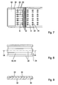
- the outflow speed of the carpet strips 22 limits the possible surface speed of the conveyor belt 1 Fig. 7 can recognize, the carpet strips formed 22 are stored offset so that each of two carpet strips 22 two adjacent juxtaposed confectionery bodies 32 are each covered in a semicircle and thus coated. This will be on the discharge belt 9 z.
Landscapes
- Life Sciences & Earth Sciences (AREA)
- Chemical & Material Sciences (AREA)
- Engineering & Computer Science (AREA)
- Food Science & Technology (AREA)
- Polymers & Plastics (AREA)
- Confectionery (AREA)
Applications Claiming Priority (2)
| Application Number | Priority Date | Filing Date | Title |
|---|---|---|---|
| DE2003132706 DE10332706B4 (de) | 2003-07-18 | 2003-07-18 | Verfahren und Vorrichtung zum einseitigen Überziehen von Süßwarenkörpern mit Überzugsmasse |
| DE10332706 | 2003-07-18 |
Publications (2)
| Publication Number | Publication Date |
|---|---|
| EP1498037A1 EP1498037A1 (de) | 2005-01-19 |
| EP1498037B1 true EP1498037B1 (de) | 2008-06-11 |
Family
ID=33461988
Family Applications (1)
| Application Number | Title | Priority Date | Filing Date |
|---|---|---|---|
| EP20040015816 Expired - Lifetime EP1498037B1 (de) | 2003-07-18 | 2004-07-06 | Verfahren und Vorrichtung zum einseitigen Überziehen von Süsswarenkörpern mit Überzugsmasse |
Country Status (3)
| Country | Link |
|---|---|
| EP (1) | EP1498037B1 (da) |
| DE (2) | DE10332706B4 (da) |
| DK (1) | DK1498037T3 (da) |
Families Citing this family (7)
| Publication number | Priority date | Publication date | Assignee | Title |
|---|---|---|---|---|
| GB0422632D0 (en) * | 2004-10-12 | 2004-11-10 | Nestec Sa | Fat-based confectionery product |
| US7556493B2 (en) * | 2005-02-24 | 2009-07-07 | Suttle James M | Methods and apparatus for molding chocolate |
| DE102008006756A1 (de) * | 2008-01-31 | 2009-08-27 | Bahlsen Gmbh & Co. Kg | Süßware, insbesondere in Form einer Dauerbackware und Verfahren zu deren Herstellung |
| US9826762B2 (en) | 2013-08-09 | 2017-11-28 | General Mills, Inc. | System and method for bottom coating food products |
| US9635873B2 (en) | 2013-08-09 | 2017-05-02 | General Mills, Inc. | System and method for bottom coating food products |
| DE102018215652A1 (de) * | 2018-09-14 | 2020-03-19 | BüHLER GMBH | Dekorierspalt |
| DE102020128147A1 (de) | 2020-10-26 | 2022-04-28 | Olaf Hanses | Injektionsverfahren zum Veredeln von Backwaren, insbesondere von Brot und Brötchen |
Family Cites Families (9)
| Publication number | Priority date | Publication date | Assignee | Title |
|---|---|---|---|---|
| GB142259A (en) * | 1919-04-03 | 1920-05-06 | Asbjorn Sonsthagen | Improvements in and relating to machines for coating chocolate bonbons |
| AU4881569A (en) * | 1969-01-08 | 1971-07-15 | Nid Pty. Limited | Caramel applicator |
| GB1546350A (en) * | 1977-05-26 | 1979-05-23 | Fullerton E | Application of a flowable material to confectins |
| IT1135974B (it) * | 1980-06-12 | 1986-08-27 | Pan Lorenz S A S | Base di trasporto per impianti di dosatura multipla,particolarmente adatta per l'industria alimentare |
| AT375006B (de) * | 1981-05-20 | 1984-06-25 | Haas Franz Waffelmasch | Vorrichtung zum beschichten einzelner auf einer transportvorrichtung aneinander anliegend transportierter waffelblaetter od. dgl. backprodukte mit streichmassen |
| DE3722288A1 (de) * | 1987-07-06 | 1989-01-19 | Sollich Gmbh & Co Kg | Verfahren und vorrichtung zur kontinuierlichen herstellung einer in stangen oder riegel zu unterteilenden, ggf. mehrschichtigen materialbahn aus noch formbarer, heisser suesswarenmasse, insbesondere karamel, fudge, gelee o. dgl. |
| DD265788A1 (de) * | 1987-10-08 | 1989-03-15 | Nagema Veb K | Bodenueberziehvorrichtung |
| DE4322414C1 (de) * | 1993-07-06 | 1994-08-25 | Sollich Gmbh & Co Kg | Vorrichtung zum Entfernen von Überzugsmasse im hinteren Bodenbereich von Warenstücken |
| GB9801132D0 (en) * | 1998-01-21 | 1998-03-18 | Cadbury Schweppes Plc | Method and apparatus of coating articles |
-
2003
- 2003-07-18 DE DE2003132706 patent/DE10332706B4/de not_active Expired - Fee Related
-
2004
- 2004-07-06 DK DK04015816T patent/DK1498037T3/da active
- 2004-07-06 EP EP20040015816 patent/EP1498037B1/de not_active Expired - Lifetime
- 2004-07-06 DE DE200450007343 patent/DE502004007343D1/de not_active Expired - Lifetime
Also Published As
| Publication number | Publication date |
|---|---|
| DE10332706B4 (de) | 2006-08-03 |
| DE502004007343D1 (de) | 2008-07-24 |
| DE10332706A1 (de) | 2005-02-24 |
| DK1498037T3 (da) | 2008-10-13 |
| EP1498037A1 (de) | 2005-01-19 |
Similar Documents
| Publication | Publication Date | Title |
|---|---|---|
| DE69321104T2 (de) | Verfahren und Vorrichtung zur Herstellung von Eiskonfekt | |
| DE3218959A1 (de) | Vorrichtung zum beschichten einzelner auf einer transportvorrichtung aneinander anliegend transportierter waffelblaetter o.dgl. backprodukte mit streichmassen | |
| DE2703331C2 (de) | Vorrichtung zum kontinuierlichen Auswalken von Teig | |
| EP0760603A1 (de) | Verfahren und vorrichtungen zum herstellen von gerollten waffeltüten oder dergleichen | |
| DE2902092A1 (de) | Spruehvorrichtung zum aufbringen von zutaten-ueberzuegen auf lebensmittel | |
| EP0134944B1 (de) | Vorrichtung zur Herstellung von Granulat | |
| DE2434140C3 (de) | Vorrichtung zum Überziehen eines Nahrungsmittels mit einer eßbaren Schicht | |
| EP1498037B1 (de) | Verfahren und Vorrichtung zum einseitigen Überziehen von Süsswarenkörpern mit Überzugsmasse | |
| DE19920071B4 (de) | Vorrichtung zum Überziehen von Warenstücken, insbesondere Süßwarenstücken, mit einer fließfähigen Überzugsmasse | |
| EP2712506B1 (de) | Walzenformer zum Ausformen eines gleichmäßigen Teppichs aus Süßwarenmasse | |
| EP0670753B1 (de) | Vorrichtung zur herstellung von granulat | |
| DE19724641C2 (de) | Vorrichtung zum Überziehen von Nahrungsmitteln, wie Süßwaren, Backwaren und dergleichen mit fließfähigen Überzugsmassen, wie Schokolade und anderen Glasuren | |
| DE102010037713A1 (de) | Vorrichtung zum Auftragen einer fließfähigen Masse auf Backwaren | |
| DE2738894C2 (de) | Vorrichtung zum Auftragen einer Überzugsmasse auf Gegenstände | |
| DE19749324A1 (de) | Vorrichtung zum Aufbereiten von kakaobutterhaltigen oder ähnlichen fetthaltigen Massen, insbesondere Schokolademasse | |
| DE2506054A1 (de) | Einrichtung zum aufbringen von streugut auf teigformlinge | |
| DE3336259C2 (de) | Vorrichtung zum Auftragen einer fließfähigen Schokoladenmasse auf Gegenstände | |
| DE4212427C1 (en) | Coating bottom of e.g. chocolate bars, biscuits, etc. - with liq. coating e.g. chocolate using arrangement of mesh belt and coating roll, for increased reliability esp. when article contains particles | |
| DE69816708T2 (de) | Vorrichtung zum Formen von Backwaren | |
| DE102005024701C5 (de) | Verfahren und Vorrichtung zum Ausformen eines Produktteppichs aus viskoser Süßwarenmasse | |
| DE4327421C2 (de) | Vorrichtung zum Einfärben von strukturierten, flächigen Teilen | |
| EP0120482B1 (de) | Vorrichtung zum Auftragen einer Schicht aus einer feinkeramischen Masse auf einen Träger | |
| EP2074888B1 (de) | Überziehmaschine für Süßwarenstücke mit einer Bodenwallstation | |
| DE60008727T2 (de) | Verfahren zum intermittierenden bilden von abgelegten schichten | |
| DE493917C (de) | Vorrichtung zur Erzeugung von streifenfoermigen UEberzuegen aus Schokolade oder aehnlicher Masse auf Zuckerwaren, Biskuiten u. dgl. |
Legal Events
| Date | Code | Title | Description |
|---|---|---|---|
| PUAI | Public reference made under article 153(3) epc to a published international application that has entered the european phase |
Free format text: ORIGINAL CODE: 0009012 |
|
| AK | Designated contracting states |
Kind code of ref document: A1 Designated state(s): AT BE BG CH CY CZ DE DK EE ES FI FR GB GR HU IE IT LI LU MC NL PL PT RO SE SI SK TR |
|
| AX | Request for extension of the european patent |
Extension state: AL HR LT LV MK |
|
| 17P | Request for examination filed |
Effective date: 20050104 |
|
| AKX | Designation fees paid |
Designated state(s): DE DK FR GB IT NL |
|
| 17Q | First examination report despatched |
Effective date: 20060801 |
|
| 17Q | First examination report despatched |
Effective date: 20060801 |
|
| GRAP | Despatch of communication of intention to grant a patent |
Free format text: ORIGINAL CODE: EPIDOSNIGR1 |
|
| GRAS | Grant fee paid |
Free format text: ORIGINAL CODE: EPIDOSNIGR3 |
|
| GRAA | (expected) grant |
Free format text: ORIGINAL CODE: 0009210 |
|
| AK | Designated contracting states |
Kind code of ref document: B1 Designated state(s): DE DK FR GB IT NL |
|
| REG | Reference to a national code |
Ref country code: GB Ref legal event code: FG4D Free format text: NOT ENGLISH |
|
| REF | Corresponds to: |
Ref document number: 502004007343 Country of ref document: DE Date of ref document: 20080724 Kind code of ref document: P |
|
| REG | Reference to a national code |
Ref country code: DK Ref legal event code: T3 |
|
| PLBE | No opposition filed within time limit |
Free format text: ORIGINAL CODE: 0009261 |
|
| STAA | Information on the status of an ep patent application or granted ep patent |
Free format text: STATUS: NO OPPOSITION FILED WITHIN TIME LIMIT |
|
| 26N | No opposition filed |
Effective date: 20090312 |
|
| REG | Reference to a national code |
Ref country code: FR Ref legal event code: PLFP Year of fee payment: 13 |
|
| REG | Reference to a national code |
Ref country code: FR Ref legal event code: PLFP Year of fee payment: 14 |
|
| PGFP | Annual fee paid to national office [announced via postgrant information from national office to epo] |
Ref country code: IT Payment date: 20170721 Year of fee payment: 14 Ref country code: FR Payment date: 20170720 Year of fee payment: 14 |
|
| PG25 | Lapsed in a contracting state [announced via postgrant information from national office to epo] |
Ref country code: FR Free format text: LAPSE BECAUSE OF NON-PAYMENT OF DUE FEES Effective date: 20180731 |
|
| PG25 | Lapsed in a contracting state [announced via postgrant information from national office to epo] |
Ref country code: IT Free format text: LAPSE BECAUSE OF NON-PAYMENT OF DUE FEES Effective date: 20180706 |
|
| PGFP | Annual fee paid to national office [announced via postgrant information from national office to epo] |
Ref country code: NL Payment date: 20220720 Year of fee payment: 19 |
|
| PGFP | Annual fee paid to national office [announced via postgrant information from national office to epo] |
Ref country code: GB Payment date: 20220725 Year of fee payment: 19 Ref country code: DK Payment date: 20220721 Year of fee payment: 19 Ref country code: DE Payment date: 20220519 Year of fee payment: 19 |
|
| REG | Reference to a national code |
Ref country code: DE Ref legal event code: R119 Ref document number: 502004007343 Country of ref document: DE |
|
| REG | Reference to a national code |
Ref country code: DK Ref legal event code: EBP Effective date: 20230731 |
|
| REG | Reference to a national code |
Ref country code: NL Ref legal event code: MM Effective date: 20230801 |
|
| GBPC | Gb: european patent ceased through non-payment of renewal fee |
Effective date: 20230706 |
|
| PG25 | Lapsed in a contracting state [announced via postgrant information from national office to epo] |
Ref country code: NL Free format text: LAPSE BECAUSE OF NON-PAYMENT OF DUE FEES Effective date: 20230801 |
|
| PG25 | Lapsed in a contracting state [announced via postgrant information from national office to epo] |
Ref country code: NL Free format text: LAPSE BECAUSE OF NON-PAYMENT OF DUE FEES Effective date: 20230801 Ref country code: DE Free format text: LAPSE BECAUSE OF NON-PAYMENT OF DUE FEES Effective date: 20240201 Ref country code: GB Free format text: LAPSE BECAUSE OF NON-PAYMENT OF DUE FEES Effective date: 20230706 |
|
| PG25 | Lapsed in a contracting state [announced via postgrant information from national office to epo] |
Ref country code: DK Free format text: LAPSE BECAUSE OF NON-PAYMENT OF DUE FEES Effective date: 20230731 |
|
| PG25 | Lapsed in a contracting state [announced via postgrant information from national office to epo] |
Ref country code: DK Free format text: LAPSE BECAUSE OF NON-PAYMENT OF DUE FEES Effective date: 20230731 |