EP1499008A2 - Méthode et système de commande pour la commutation électronique de moteurs DC sans balais - Google Patents
Méthode et système de commande pour la commutation électronique de moteurs DC sans balais Download PDFInfo
- Publication number
- EP1499008A2 EP1499008A2 EP04011481A EP04011481A EP1499008A2 EP 1499008 A2 EP1499008 A2 EP 1499008A2 EP 04011481 A EP04011481 A EP 04011481A EP 04011481 A EP04011481 A EP 04011481A EP 1499008 A2 EP1499008 A2 EP 1499008A2
- Authority
- EP
- European Patent Office
- Prior art keywords
- winding
- current
- rotor
- motor
- currents
- Prior art date
- Legal status (The legal status is an assumption and is not a legal conclusion. Google has not performed a legal analysis and makes no representation as to the accuracy of the status listed.)
- Granted
Links
Images

Classifications
-
- H—ELECTRICITY
- H02—GENERATION; CONVERSION OR DISTRIBUTION OF ELECTRIC POWER
- H02P—CONTROL OR REGULATION OF ELECTRIC MOTORS, ELECTRIC GENERATORS OR DYNAMO-ELECTRIC CONVERTERS; CONTROLLING TRANSFORMERS, REACTORS OR CHOKE COILS
- H02P6/00—Arrangements for controlling synchronous motors or other dynamo-electric motors using electronic commutation dependent on the rotor position; Electronic commutators therefor
- H02P6/10—Arrangements for controlling torque ripple, e.g. providing reduced torque ripple
-
- H—ELECTRICITY
- H02—GENERATION; CONVERSION OR DISTRIBUTION OF ELECTRIC POWER
- H02P—CONTROL OR REGULATION OF ELECTRIC MOTORS, ELECTRIC GENERATORS OR DYNAMO-ELECTRIC CONVERTERS; CONTROLLING TRANSFORMERS, REACTORS OR CHOKE COILS
- H02P6/00—Arrangements for controlling synchronous motors or other dynamo-electric motors using electronic commutation dependent on the rotor position; Electronic commutators therefor
- H02P6/14—Electronic commutators
- H02P6/16—Circuit arrangements for detecting position
- H02P6/18—Circuit arrangements for detecting position without separate position detecting elements
- H02P6/182—Circuit arrangements for detecting position without separate position detecting elements using back-emf in windings
Definitions
- the present invention relates to a method for commutating a brushless DC motor according to the preamble of claim 1 and a corresponding control system according to the preamble of claim 16. Further relates the invention also includes a brushless DC motor for commutating the method according to the invention is equipped with such a control system.
- Permanently excited, electronically commutated DC motors are used today for many applications because compared to motors which have mechanical commutators (brushes), by avoiding wear parts (commutator, brushes, slip rings) even without special maintenance measures have a high life expectancy. moreover Such permanent-magnet motors are characterized by good efficiency and efficiency high energy density. An important area of application of such EC motors are Fans in which quiet operation is playing an increasingly important role. In this regard, known motor designs and commutation are still in need of improvement.
- Such an EC motor typically has an approximately trapezoidal Air gap induction.
- the commutation electronics of a three-speed motor consists from a semiconductor bridge with six electronic switching elements (transistors). In a conventional block commutation these are pairwise so switched on that a magnetic stator rotating field is generated. This results six possible switching states, which alternate periodically.
- the speed of the Motors can be controlled by the effective motor voltage. This will either the supply voltage, the so-called DC link voltage, changed, or it is one of the two conductive transistors pulse-width modulated clocked (PWM).
- PWM pulse-width modulated clocked
- a favorable solution offers a likewise known sensorless rotor position detection.
- sensorless means that no sensors as separate components are provided to detect mechanical variables directly. Rather, for an indirect detection of the rotor position uses only electrically measurable quantities.
- EP 1 104 087 A2 describes measures for controlling a DC motor, where a sinusoidal voltage / current curve is specified with gaps.
- suitable motors must also have a sinusoidal air gap induction, d. H. have sinusoidally induced induced winding voltages, and have This has the disadvantage that they compared to otherwise standard EC motors a lower Own use. This means that for the same engine torque larger volume of construction is required.
- EC motors with essentially trapezoidal air gap induction is therefore not the known sinusoidal course suitable.
- the inserted power gaps lead to an increase in Torque fluctuation compared to the ideal sinusoidal shape.
- the present invention is based on the object for controlling brushless DC motors, a method and a control system of the beginning described, generic type to create what a particularly quiet, low-noise operation with high efficiency using a robust, d.
- H. Non-susceptible and cost-effective rotor position detection without separate Rotor position sensors is achieved.
- the Wicking currents with a certain, from the course of the in the Winding phases induced pole wheel stresses dependent desired course in such a way be predetermined to be a predetermined over the rotor rotation Motor torque continuously over the engine rotation away without Abrupt, switch-related jumps run and power gaps for the sensorless Have rotor position detection.
- the motor or its winding strands with respect to their time course specially generated (generated) winding currents controlled the waveform is selected and specified so that a certain, preferably uniform (constant) torque arises.
- the generated power gaps is advantageously a sensorless rotor position detection by evaluating the induced pole wheel voltages possible by this can be detected in each case at just not driven winding strand.
- the winding currents can in principle any suitable Method be applied. So can be used with advantage a current regulator, the desired, predetermined current form is specified as a setpoint, and then adjusts the actual values of the currents according to the setpoints. alternative can also - without current measurement - to achieve a predetermined Course of current necessary voltage curve given and, for example, in one Memory are stored. Also conceivable is a dynamic calculation ("online") of the required voltage during operation, e.g. one mathematical model of the engine is stored in the control unit. Corresponding The so-called “reference voltage curve” is then the stator voltage of Motor specified in particular by pulse width modulation (PWM).
- PWM pulse width modulation
- the width or more appropriate the time length of the current gaps in adaptation to the respective operating state in particular acceleration or stationary operation with uniform (constant) Speed
- the respective operating state in particular acceleration or stationary operation with uniform (constant) Speed
- a relative Great acceleration will provide a larger power gap despite possible interpolation error, a secure acquisition and evaluation of the To ensure pole wheel voltage.
- a reduction of Efficiency in terms of a better dynamic behavior of the engine in Purchase taken.
- stationary operation at a uniform speed is the Current gap on the other hand to a smaller, for the rotor position detection just yet sufficient width or length reduced, so that a total of a higher Efficiency is achieved.
- the invention also includes a brushless DC motor which comprises using the method according to the invention with a Control system is equipped according to the invention.
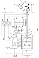
- a three-phase brushless DC motor 1 is shown very schematically with its stator 2 and a permanent magnet rotor 4.
- the stator 2 has three winding strands a, b and c, which are arranged here in Stem circuit, for example.
- the winding strands a, b, c are for the rotary drive of the rotor 4 by a control circuit 6 for generating a magnetic stator field in response to the rotor position (rotational position) with winding currents i a , i b , i c driven.
- the control circuit 6 has a bridge circuit 8 with electronic switching elements T1 to T6 as well as a control unit 10 that controls them.
- the control unit 10 may advantageously be formed by a microcontroller .mu.C.
- the bridge circuit 8 is a full bridge of six electronic switching elements T1 to T6.
- the bridge circuit 8 is fed on the input side via a DC voltage intermediate circuit U DC and is connected on the output side via three winding connection lines A, B, C to the three winding phases a, b, and c of the motor 1.
- the switching elements T1 to T6 are controlled by the control unit 10 via control signals G 1 to G 6 . In that regard, this is known per se.
- a filter 12 is connected to the sensorless rotor position detection, which is to suppress the PWM-related switching frequency.
- the voltages filtered here are, on the one hand, fed directly to a comparator K1, K2, K3 and, on the other hand, to a device 14 for motor star point simulation, which generates a reference voltage u ref , which is likewise fed to the comparators K1, K2, K3.
- the filtered output voltages u ' a , u' b and u ' c are compared with the reference voltage u ref by the comparators K1 to K3, thereby providing digital output signals P a , P b , P c , which are the polarity of the induced in the motor winding strands Specify voltages. These signals are supplied to the control unit 10.
- the control unit 10 may have a control signal input SS and a feedback output RM.
- a current controller is integrated, which may be stored, for example as a digital algorithm. This current controller compares the current actual values with internally stored, according to the invention predetermined current setpoint curves i aSoll , i bSoll .
- the voltage at the terminals of the motor winding phases a, b, c can be advantageously changed by suitable control of the switching elements of the bridge circuit 8 via a suitable pulse width modulation (PWM) such that desired and actual values are as possible good match.
- PWM pulse width modulation
- the rotor position detection takes place in a manner known per se sensorless by evaluation of the induced in the motor winding strands a, b, c due to the rotating permanent magnet rotor 4 voltages (signals P a , P b , P c ).
- flow control make sure that the currents are given in such a way that time phases alternate, in which either all three or only two winding strands energized become. It is basically irrelevant whether the engine 1 in star (like shown) or is connected in delta. For simplicity, refer the following explanations to the star circuit shown in Fig. 1, however The method according to the invention can also be used analogously for motors in delta connection be applied.
- the rotor position is determined from the detection of the Polradbeginn. For this purpose, the voltage in the currently not energized motor line is evaluated. In the simplest case, only the polarity of this voltage or its zero crossings is detected. This results in six pulses per electrical revolution. Since in many applications with a relatively large moment of inertia, as often in fan applications, the speed can only change relatively slowly, it can be assumed that the rotor position ⁇ between two pulses with interpolation can be determined accurately enough.
- the control unit 10 If the rotor position-dependent values of the pole wheel voltage u pa ( ⁇ ), ⁇ pb ( ⁇ ) and ⁇ pc ( ⁇ ) are stored in the controller and the motor currents i a (t), i b (t) and i c (t) are measured the control unit 10 "online” at any time the current torque m or calculate the required for a specific torque currents. However, the same calculations can also be carried out "offline", ie, the current waveforms required for a desired torque curve are calculated in advance and z. B. stored in the form of a table in the control unit.
- the motor currents are predetermined so that the calculated torque m remains uniform, preferably constant.
- Essential to the present invention is now the realization that instead of the third degree of freedom is used to control the rate of change of current during commutation. As a result, although the deteriorated Efficiency, the acoustic noise but are significantly lower, the otherwise disturbing commutation noises disappear.
- i a (t) i a (t 1 ) ⁇ (T 2 -t) / (t 2 - t 1 ) if t 1 ⁇ t ⁇ t 2 .
- t 1 is the time when the time phase starts with three energized motor lines
- t 2 is the time when the next time phase begins with two lines energized.
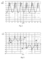
- Fig. 5 the current waveforms according to the cosine function can be seen.
- the Current gaps in the current flow in each case in the range of the zero crossing of Pole-wheel voltage enables cost-effective and robust sensorless detection the rotor position. Due to the power gaps but not the maximum possible Range can be used for torque generation. For the same Motor torque, a larger effective winding current is required.
- the Gaps therefore increase the copper losses in the engine compared to the operation without Electricity gaps. With increasing width (time length) worsens the Motor efficiency.
- this disadvantage is eliminated by that the width or time length of the power gaps depending on instantaneous operating state of the engine is changed. At relatively large Acceleration is inserted a larger current gap to despite interpolation error to ensure reliable detection of the zero crossings. In this case, a Reduction of the efficiency with regard to a better dynamic behavior the engine accepted. In stationary operation, d. H. with uniform or constant speed, the current gap, on the other hand, to a small, for the Lüer charged just enough width reduced, reducing the efficiency is optimized. Again, to achieve a quiet engine operation of the Current history predetermined so that it leads to a uniform motor torque and at the same time has no rapid changes in current.
- the current shape can for the desired current gap width, for example on the following relationships are calculated.
- the current slope and the change in the current gradient are preferably limited. It is therefore the first and second derivative of the current after the time or after the rotation angle.
- the limit ⁇ and for the change of the limit A is specified.
- the specified equation systems for the current ranges with and without current gap can be used to determine the desired current curves according to conventional numerical methods be solved offline or online.
- the gradients are called Function of the angle of rotation and the width of the current gap in the scheme or in the Control unit 10 deposited.
- the solution is during the Execution of the control continuously recalculated.
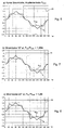
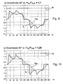
- FIGS. 6 to 10 illustrate by way of example the current profiles thus calculated for different wide power gaps taking into account the optimum Course without current gap (Fig. 6) related copper losses of the engine.
- the Current gap is preferably increased when the engine accelerates, d. H. if the zero crossing of the Polradschreib at an earlier time with respect to interpolated angle occurs.
- the current controller is a current setpoint curve, for example, as shown in FIG. 9 or 10, with a wider current gap before Zero crossing of the Polradschreib supplied. This happens z. B. at an increase of the torque setpoint (current setpoint amplitude), which remains constant Lastmoment leads to an acceleration of the engine.
- the current gap is then reduced when the angular acceleration of the motor is small, or if it operates at a steady speed (stationary).
- the Current regulator is this a current setpoint curve, for example, as shown in FIG. 7 or 8 with a relatively smaller current gap before the zero crossing of the Polradbeginning.
- the angular acceleration can be over the temporal change of Engine speed, which is already known for the angular interpolation, are determined.
- Another advantageous possibility is the comparison of the interpolated rotation angle with the real angle of rotation of the motor at the time of zero crossing the
- the inventive method described allows a low noise Motor operation with high efficiency and at the same time a cost-effective sensorless rotor position detection via the acquisition and evaluation the pole wheel voltage of the motor.
- a comparable engine efficiency can be achieved, as in an operation with Rotor position sensors. This is particularly advantageous in applications where the Engine speed is not changed frequently, as for example with fans and Pumps is the case.
- the invention is not limited to the illustrated and described embodiments (three-phase motor, star connection, magnetization shape, etc.) limited, but also includes all the same in the sense of the inventions embodiments. So can the motor also have a different number of strings and / or in delta connection be switched. It should be mentioned again that the invention is not limited to the Use of a current controller is limited, but the desired current shape can also be achieved without current measurement by suitable modulation of the voltage become.
- the invention is not limited to those in the independent claims each containing feature combination limited, but can also by any other combination of individual features of all disclosed Be defined characteristics. In this respect, the claims are only the first To understand formulation attempt for an invention.
Landscapes
- Engineering & Computer Science (AREA)
- Power Engineering (AREA)
- Control Of Motors That Do Not Use Commutators (AREA)
Applications Claiming Priority (2)
| Application Number | Priority Date | Filing Date | Title |
|---|---|---|---|
| DE10332381 | 2003-07-17 | ||
| DE10332381A DE10332381A1 (de) | 2003-07-17 | 2003-07-17 | Verfahren und Steuersystem zur elektronischen Kommutierung eines bürstenlosen Gleichstrommotors |
Publications (3)
| Publication Number | Publication Date |
|---|---|
| EP1499008A2 true EP1499008A2 (fr) | 2005-01-19 |
| EP1499008A3 EP1499008A3 (fr) | 2006-01-11 |
| EP1499008B1 EP1499008B1 (fr) | 2008-10-08 |
Family
ID=33461961
Family Applications (1)
| Application Number | Title | Priority Date | Filing Date |
|---|---|---|---|
| EP04011481A Expired - Lifetime EP1499008B1 (fr) | 2003-07-17 | 2004-05-14 | Méthode et système de commande pour la commutation électronique d'un moteur DC sans balais |
Country Status (4)
| Country | Link |
|---|---|
| EP (1) | EP1499008B1 (fr) |
| AT (1) | ATE410816T1 (fr) |
| DE (2) | DE10332381A1 (fr) |
| ES (1) | ES2314314T3 (fr) |
Cited By (23)
| Publication number | Priority date | Publication date | Assignee | Title |
|---|---|---|---|---|
| EP2164164A1 (fr) | 2008-09-10 | 2010-03-17 | ebm-papst Mulfingen GmbH & Co.KG | Procédé et système de commande destinés au fonctionnement d'un moteur électrique sans balais |
| CN101951211A (zh) * | 2010-07-23 | 2011-01-19 | 南京航空航天大学 | 基于自适应滑模观测器的无刷直流电机电磁转矩观测方法 |
| EP2289756A1 (fr) | 2009-08-26 | 2011-03-02 | ROFA Rosenheimer Förderanlagen GmbH | Système de transport par rail électrique |
| CN102522929A (zh) * | 2011-12-21 | 2012-06-27 | 江门市胜思特电器有限公司 | 一种低压无刷直流电动机抽头式调速方法 |
| CN103501140A (zh) * | 2013-10-11 | 2014-01-08 | 昆山市润苏物资有限公司 | 一种基于单片机的永磁无刷直流电机控制系统 |
| CN104653770A (zh) * | 2013-11-25 | 2015-05-27 | 陕西国力信息技术有限公司 | 无刷直流电机用于汽车离合的大扭矩精确自锁 |
| CN104660116A (zh) * | 2013-11-25 | 2015-05-27 | 陕西国力信息技术有限公司 | 无刷直流电机用于汽车换挡的低速大功率 |
| CN104660117A (zh) * | 2013-11-25 | 2015-05-27 | 陕西国力信息技术有限公司 | 无刷直流电机用于汽车离合的低速大功率 |
| CN104653768A (zh) * | 2013-11-25 | 2015-05-27 | 陕西国力信息技术有限公司 | 无刷直流电机用于汽车选档的大扭矩精确自锁 |
| CN105610369A (zh) * | 2016-03-04 | 2016-05-25 | 合肥工业大学 | 一种基于滑模观测器的异步电机磁链观测方法 |
| CN104158447B (zh) * | 2014-08-12 | 2016-11-30 | 南京航空航天大学 | 一种无刷直流电机控制方法 |
| US9645584B2 (en) | 2014-09-17 | 2017-05-09 | Honeywell International Inc. | Gas valve with electronic health monitoring |
| US9657946B2 (en) | 2012-09-15 | 2017-05-23 | Honeywell International Inc. | Burner control system |
| US9683674B2 (en) | 2013-10-29 | 2017-06-20 | Honeywell Technologies Sarl | Regulating device |
| US9835265B2 (en) | 2011-12-15 | 2017-12-05 | Honeywell International Inc. | Valve with actuator diagnostics |
| US9841122B2 (en) | 2014-09-09 | 2017-12-12 | Honeywell International Inc. | Gas valve with electronic valve proving system |
| US9846440B2 (en) | 2011-12-15 | 2017-12-19 | Honeywell International Inc. | Valve controller configured to estimate fuel comsumption |
| US9851103B2 (en) | 2011-12-15 | 2017-12-26 | Honeywell International Inc. | Gas valve with overpressure diagnostics |
| CN106059405B (zh) * | 2016-05-30 | 2018-04-27 | 西北工业大学 | 能够抑制转矩脉动的大功率双转无刷直流电机换相方法 |
| US9995486B2 (en) | 2011-12-15 | 2018-06-12 | Honeywell International Inc. | Gas valve with high/low gas pressure detection |
| US10024439B2 (en) | 2013-12-16 | 2018-07-17 | Honeywell International Inc. | Valve over-travel mechanism |
| US10422531B2 (en) | 2012-09-15 | 2019-09-24 | Honeywell International Inc. | System and approach for controlling a combustion chamber |
| US10503181B2 (en) | 2016-01-13 | 2019-12-10 | Honeywell International Inc. | Pressure regulator |
Families Citing this family (10)
| Publication number | Priority date | Publication date | Assignee | Title |
|---|---|---|---|---|
| DE102009028582A1 (de) | 2009-08-17 | 2011-02-24 | Robert Bosch Gmbh | Elektronisch kommutierter Elektromotor mit einer Rotorpositions-Prädiktion und einer Interpolation und Verfahren |
| US8899264B2 (en) | 2011-12-15 | 2014-12-02 | Honeywell International Inc. | Gas valve with electronic proof of closure system |
| US9074770B2 (en) | 2011-12-15 | 2015-07-07 | Honeywell International Inc. | Gas valve with electronic valve proving system |
| US8839815B2 (en) | 2011-12-15 | 2014-09-23 | Honeywell International Inc. | Gas valve with electronic cycle counter |
| US9557059B2 (en) | 2011-12-15 | 2017-01-31 | Honeywell International Inc | Gas valve with communication link |
| US8947242B2 (en) | 2011-12-15 | 2015-02-03 | Honeywell International Inc. | Gas valve with valve leakage test |
| US8905063B2 (en) | 2011-12-15 | 2014-12-09 | Honeywell International Inc. | Gas valve with fuel rate monitor |
| US10564062B2 (en) | 2016-10-19 | 2020-02-18 | Honeywell International Inc. | Human-machine interface for gas valve |
| US11073281B2 (en) | 2017-12-29 | 2021-07-27 | Honeywell International Inc. | Closed-loop programming and control of a combustion appliance |
| US10697815B2 (en) | 2018-06-09 | 2020-06-30 | Honeywell International Inc. | System and methods for mitigating condensation in a sensor module |
Family Cites Families (3)
| Publication number | Priority date | Publication date | Assignee | Title |
|---|---|---|---|---|
| WO1994011945A1 (fr) * | 1992-11-06 | 1994-05-26 | Georgia Tech Research Corporation | Procede de commande base sur l'observation de moteurs synchrones a aimants permanents |
| DE19815425A1 (de) * | 1998-04-07 | 1999-10-14 | Bosch Gmbh Robert | Verfahren und Vorrichtung zur Ansteuerung eines elektronisch kommutierten Mehrphasen-Gleichstrommotors |
| US6369535B1 (en) * | 2001-07-31 | 2002-04-09 | General Electric Company | Method and apparatus for current shaping in electronically commutated motors |
-
2003
- 2003-07-17 DE DE10332381A patent/DE10332381A1/de not_active Withdrawn
-
2004
- 2004-05-14 ES ES04011481T patent/ES2314314T3/es not_active Expired - Lifetime
- 2004-05-14 AT AT04011481T patent/ATE410816T1/de not_active IP Right Cessation
- 2004-05-14 EP EP04011481A patent/EP1499008B1/fr not_active Expired - Lifetime
- 2004-05-14 DE DE502004008183T patent/DE502004008183D1/de not_active Expired - Lifetime
Cited By (25)
| Publication number | Priority date | Publication date | Assignee | Title |
|---|---|---|---|---|
| EP2164164A1 (fr) | 2008-09-10 | 2010-03-17 | ebm-papst Mulfingen GmbH & Co.KG | Procédé et système de commande destinés au fonctionnement d'un moteur électrique sans balais |
| EP2289756A1 (fr) | 2009-08-26 | 2011-03-02 | ROFA Rosenheimer Förderanlagen GmbH | Système de transport par rail électrique |
| CN101951211A (zh) * | 2010-07-23 | 2011-01-19 | 南京航空航天大学 | 基于自适应滑模观测器的无刷直流电机电磁转矩观测方法 |
| US9995486B2 (en) | 2011-12-15 | 2018-06-12 | Honeywell International Inc. | Gas valve with high/low gas pressure detection |
| US9835265B2 (en) | 2011-12-15 | 2017-12-05 | Honeywell International Inc. | Valve with actuator diagnostics |
| US9851103B2 (en) | 2011-12-15 | 2017-12-26 | Honeywell International Inc. | Gas valve with overpressure diagnostics |
| US9846440B2 (en) | 2011-12-15 | 2017-12-19 | Honeywell International Inc. | Valve controller configured to estimate fuel comsumption |
| CN102522929A (zh) * | 2011-12-21 | 2012-06-27 | 江门市胜思特电器有限公司 | 一种低压无刷直流电动机抽头式调速方法 |
| US11421875B2 (en) | 2012-09-15 | 2022-08-23 | Honeywell International Inc. | Burner control system |
| US10422531B2 (en) | 2012-09-15 | 2019-09-24 | Honeywell International Inc. | System and approach for controlling a combustion chamber |
| US9657946B2 (en) | 2012-09-15 | 2017-05-23 | Honeywell International Inc. | Burner control system |
| CN103501140A (zh) * | 2013-10-11 | 2014-01-08 | 昆山市润苏物资有限公司 | 一种基于单片机的永磁无刷直流电机控制系统 |
| US10215291B2 (en) | 2013-10-29 | 2019-02-26 | Honeywell International Inc. | Regulating device |
| US9683674B2 (en) | 2013-10-29 | 2017-06-20 | Honeywell Technologies Sarl | Regulating device |
| CN104660116A (zh) * | 2013-11-25 | 2015-05-27 | 陕西国力信息技术有限公司 | 无刷直流电机用于汽车换挡的低速大功率 |
| CN104653768A (zh) * | 2013-11-25 | 2015-05-27 | 陕西国力信息技术有限公司 | 无刷直流电机用于汽车选档的大扭矩精确自锁 |
| CN104660117A (zh) * | 2013-11-25 | 2015-05-27 | 陕西国力信息技术有限公司 | 无刷直流电机用于汽车离合的低速大功率 |
| CN104653770A (zh) * | 2013-11-25 | 2015-05-27 | 陕西国力信息技术有限公司 | 无刷直流电机用于汽车离合的大扭矩精确自锁 |
| US10024439B2 (en) | 2013-12-16 | 2018-07-17 | Honeywell International Inc. | Valve over-travel mechanism |
| CN104158447B (zh) * | 2014-08-12 | 2016-11-30 | 南京航空航天大学 | 一种无刷直流电机控制方法 |
| US9841122B2 (en) | 2014-09-09 | 2017-12-12 | Honeywell International Inc. | Gas valve with electronic valve proving system |
| US9645584B2 (en) | 2014-09-17 | 2017-05-09 | Honeywell International Inc. | Gas valve with electronic health monitoring |
| US10503181B2 (en) | 2016-01-13 | 2019-12-10 | Honeywell International Inc. | Pressure regulator |
| CN105610369A (zh) * | 2016-03-04 | 2016-05-25 | 合肥工业大学 | 一种基于滑模观测器的异步电机磁链观测方法 |
| CN106059405B (zh) * | 2016-05-30 | 2018-04-27 | 西北工业大学 | 能够抑制转矩脉动的大功率双转无刷直流电机换相方法 |
Also Published As
| Publication number | Publication date |
|---|---|
| DE502004008183D1 (de) | 2008-11-20 |
| ES2314314T3 (es) | 2009-03-16 |
| EP1499008A3 (fr) | 2006-01-11 |
| DE10332381A1 (de) | 2005-02-03 |
| EP1499008B1 (fr) | 2008-10-08 |
| ATE410816T1 (de) | 2008-10-15 |
Similar Documents
| Publication | Publication Date | Title |
|---|---|---|
| EP1499008B1 (fr) | Méthode et système de commande pour la commutation électronique d'un moteur DC sans balais | |
| DE69725231T2 (de) | Einphasiger Permanentmagnetmotor | |
| EP1154555B1 (fr) | Système de commutation électronique pour un moteur à courant continu sans balai | |
| DE4310260C1 (de) | Elektronische Steuervorrichtung für einen elektronisch kommutierten Gleichstrommotor (EC-Motor) | |
| DE19860446A1 (de) | Verfahren zur Regelung eines spannungs-/frequenzumrichtergesteuerten Mehrphasen-Permanentmagnetmotors | |
| EP1076408B1 (fr) | Procédé de démarrage d'un moteur à courant continu sans balais | |
| DE4314211C2 (de) | Verfahren zur Steuerung des Abschaltvorgangs in den Strängen eines Reluktanzmotors | |
| DE69029511T2 (de) | Reluktanzmotor | |
| DE102008058955A1 (de) | Elektronisch kommutierter Motor | |
| EP3213402A1 (fr) | Actionneur équipé d'un moteur à courant continu biphasé sans balai et utilisation d'un tel moteur à courant continu | |
| EP1523090A2 (fr) | Procédé pour la commutation d'un moteur à courant continu sans balais | |
| DE4425193C1 (de) | Drehzahlverstellbarer EC-Gleichstrommotor | |
| DE102014107949A1 (de) | Verfahren und Vorrichtung zur Erkennung eines Nulldurchgangs eines Stroms durch einen Strang eines bürstenlosen Gleichstrom- motors | |
| WO2013110501A2 (fr) | Procédé pour commander un moteur bldc | |
| DE10332228B4 (de) | Steuerungsverfahren für einen bürstenlosen Elektromotor, insbesonde Lüftermotor | |
| DE102016222015A1 (de) | Elektrischer Antrieb und Verfahren zum Betrieb eines Elektromotors | |
| DE102016215175A1 (de) | Verfahren zum Betreiben einer elektrischen Maschine und elektrische Maschine | |
| DE102012012762B4 (de) | Einrichtung zur Bestimmung von Positionen eines Rotors in elektrischen Maschinen | |
| DE10127670A1 (de) | Bürstenloser dreiphasiger Elektromotor und Verfahren zu dessen Ansteuerung | |
| EP1443635A1 (fr) | Procédé de contrôle d'un angle de déclenchement | |
| BE1029061B1 (de) | Verfahren zum Ansteuern eines mindestens zweiphasigen bürstenlosen Motors | |
| DE2452082A1 (de) | Kollektorloser gleichstrommotor mit einstraengiger statorwicklung | |
| EP0190240B1 (fr) | Moteur a courant continu depourvu de collecteur | |
| DE10163886A1 (de) | Verfahren zur elektronischen Kommutierung eines bürstenlosen Gleichstrommotors | |
| EP1112614A1 (fr) | Systeme d'entrainement electrique a moteur a courant continu commute electroniquement pour reduire l'ondulation de couple |
Legal Events
| Date | Code | Title | Description |
|---|---|---|---|
| PUAI | Public reference made under article 153(3) epc to a published international application that has entered the european phase |
Free format text: ORIGINAL CODE: 0009012 |
|
| AK | Designated contracting states |
Kind code of ref document: A2 Designated state(s): AT BE BG CH CY CZ DE DK EE ES FI FR GB GR HU IE IT LI LU MC NL PL PT RO SE SI SK TR |
|
| AX | Request for extension of the european patent |
Extension state: AL HR LT LV MK |
|
| PUAL | Search report despatched |
Free format text: ORIGINAL CODE: 0009013 |
|
| AK | Designated contracting states |
Kind code of ref document: A3 Designated state(s): AT BE BG CH CY CZ DE DK EE ES FI FR GB GR HU IE IT LI LU MC NL PL PT RO SE SI SK TR |
|
| AX | Request for extension of the european patent |
Extension state: AL HR LT LV MK |
|
| RIC1 | Information provided on ipc code assigned before grant |
Ipc: H02P 6/14 19950101ALI20051119BHEP Ipc: H02P 6/18 19950101ALI20051119BHEP Ipc: H02P 6/10 19950101AFI20041103BHEP |
|
| 17P | Request for examination filed |
Effective date: 20060322 |
|
| AKX | Designation fees paid |
Designated state(s): AT BE BG CH CY CZ DE DK EE ES FI FR GB GR HU IE IT LI LU MC NL PL PT RO SE SI SK TR |
|
| RTI1 | Title (correction) |
Free format text: METHOD AND CONTROL SYSTEM FOR ELECTRONIC COMMUTATION OF A BRUSHLESS DC MOTOR |
|
| GRAP | Despatch of communication of intention to grant a patent |
Free format text: ORIGINAL CODE: EPIDOSNIGR1 |
|
| RIN1 | Information on inventor provided before grant (corrected) |
Inventor name: KROTSCH, JENS, DIPL.-ING. (FH) Inventor name: LELKES, ANDRAS, DR.-ING. |
|
| GRAS | Grant fee paid |
Free format text: ORIGINAL CODE: EPIDOSNIGR3 |
|
| GRAA | (expected) grant |
Free format text: ORIGINAL CODE: 0009210 |
|
| AK | Designated contracting states |
Kind code of ref document: B1 Designated state(s): AT BE BG CH CY CZ DE DK EE ES FI FR GB GR HU IE IT LI LU MC NL PL PT RO SE SI SK TR |
|
| REG | Reference to a national code |
Ref country code: GB Ref legal event code: FG4D Free format text: NOT ENGLISH |
|
| REG | Reference to a national code |
Ref country code: CH Ref legal event code: EP |
|
| REG | Reference to a national code |
Ref country code: IE Ref legal event code: FG4D Free format text: LANGUAGE OF EP DOCUMENT: GERMAN |
|
| REF | Corresponds to: |
Ref document number: 502004008183 Country of ref document: DE Date of ref document: 20081120 Kind code of ref document: P |
|
| PG25 | Lapsed in a contracting state [announced via postgrant information from national office to epo] |
Ref country code: SI Free format text: LAPSE BECAUSE OF FAILURE TO SUBMIT A TRANSLATION OF THE DESCRIPTION OR TO PAY THE FEE WITHIN THE PRESCRIBED TIME-LIMIT Effective date: 20081008 |
|
| REG | Reference to a national code |
Ref country code: ES Ref legal event code: FG2A Ref document number: 2314314 Country of ref document: ES Kind code of ref document: T3 |
|
| NLV1 | Nl: lapsed or annulled due to failure to fulfill the requirements of art. 29p and 29m of the patents act | ||
| PG25 | Lapsed in a contracting state [announced via postgrant information from national office to epo] |
Ref country code: BG Free format text: LAPSE BECAUSE OF FAILURE TO SUBMIT A TRANSLATION OF THE DESCRIPTION OR TO PAY THE FEE WITHIN THE PRESCRIBED TIME-LIMIT Effective date: 20090108 |
|
| PG25 | Lapsed in a contracting state [announced via postgrant information from national office to epo] |
Ref country code: PT Free format text: LAPSE BECAUSE OF FAILURE TO SUBMIT A TRANSLATION OF THE DESCRIPTION OR TO PAY THE FEE WITHIN THE PRESCRIBED TIME-LIMIT Effective date: 20090218 Ref country code: FI Free format text: LAPSE BECAUSE OF FAILURE TO SUBMIT A TRANSLATION OF THE DESCRIPTION OR TO PAY THE FEE WITHIN THE PRESCRIBED TIME-LIMIT Effective date: 20081008 Ref country code: PL Free format text: LAPSE BECAUSE OF FAILURE TO SUBMIT A TRANSLATION OF THE DESCRIPTION OR TO PAY THE FEE WITHIN THE PRESCRIBED TIME-LIMIT Effective date: 20081008 Ref country code: NL Free format text: LAPSE BECAUSE OF FAILURE TO SUBMIT A TRANSLATION OF THE DESCRIPTION OR TO PAY THE FEE WITHIN THE PRESCRIBED TIME-LIMIT Effective date: 20081008 |
|
| REG | Reference to a national code |
Ref country code: IE Ref legal event code: FD4D |
|
| PG25 | Lapsed in a contracting state [announced via postgrant information from national office to epo] |
Ref country code: RO Free format text: LAPSE BECAUSE OF FAILURE TO SUBMIT A TRANSLATION OF THE DESCRIPTION OR TO PAY THE FEE WITHIN THE PRESCRIBED TIME-LIMIT Effective date: 20081008 Ref country code: EE Free format text: LAPSE BECAUSE OF FAILURE TO SUBMIT A TRANSLATION OF THE DESCRIPTION OR TO PAY THE FEE WITHIN THE PRESCRIBED TIME-LIMIT Effective date: 20081008 Ref country code: IE Free format text: LAPSE BECAUSE OF FAILURE TO SUBMIT A TRANSLATION OF THE DESCRIPTION OR TO PAY THE FEE WITHIN THE PRESCRIBED TIME-LIMIT Effective date: 20081008 Ref country code: DK Free format text: LAPSE BECAUSE OF FAILURE TO SUBMIT A TRANSLATION OF THE DESCRIPTION OR TO PAY THE FEE WITHIN THE PRESCRIBED TIME-LIMIT Effective date: 20081008 |
|
| PLBE | No opposition filed within time limit |
Free format text: ORIGINAL CODE: 0009261 |
|
| STAA | Information on the status of an ep patent application or granted ep patent |
Free format text: STATUS: NO OPPOSITION FILED WITHIN TIME LIMIT |
|
| REG | Reference to a national code |
Ref country code: HU Ref legal event code: AG4A Ref document number: E005350 Country of ref document: HU |
|
| PG25 | Lapsed in a contracting state [announced via postgrant information from national office to epo] |
Ref country code: SE Free format text: LAPSE BECAUSE OF FAILURE TO SUBMIT A TRANSLATION OF THE DESCRIPTION OR TO PAY THE FEE WITHIN THE PRESCRIBED TIME-LIMIT Effective date: 20090108 |
|
| 26N | No opposition filed |
Effective date: 20090709 |
|
| PG25 | Lapsed in a contracting state [announced via postgrant information from national office to epo] |
Ref country code: SK Free format text: LAPSE BECAUSE OF FAILURE TO SUBMIT A TRANSLATION OF THE DESCRIPTION OR TO PAY THE FEE WITHIN THE PRESCRIBED TIME-LIMIT Effective date: 20081008 |
|
| BERE | Be: lapsed |
Owner name: EBM-PAPST MULFINGEN G.M.B.H. & CO.KG Effective date: 20090531 |
|
| PG25 | Lapsed in a contracting state [announced via postgrant information from national office to epo] |
Ref country code: MC Free format text: LAPSE BECAUSE OF NON-PAYMENT OF DUE FEES Effective date: 20090531 |
|
| REG | Reference to a national code |
Ref country code: CH Ref legal event code: PL |
|
| PG25 | Lapsed in a contracting state [announced via postgrant information from national office to epo] |
Ref country code: LI Free format text: LAPSE BECAUSE OF NON-PAYMENT OF DUE FEES Effective date: 20090531 Ref country code: CH Free format text: LAPSE BECAUSE OF NON-PAYMENT OF DUE FEES Effective date: 20090531 |
|
| PG25 | Lapsed in a contracting state [announced via postgrant information from national office to epo] |
Ref country code: BE Free format text: LAPSE BECAUSE OF NON-PAYMENT OF DUE FEES Effective date: 20090531 |
|
| PG25 | Lapsed in a contracting state [announced via postgrant information from national office to epo] |
Ref country code: AT Free format text: LAPSE BECAUSE OF NON-PAYMENT OF DUE FEES Effective date: 20090514 |
|
| PG25 | Lapsed in a contracting state [announced via postgrant information from national office to epo] |
Ref country code: GR Free format text: LAPSE BECAUSE OF FAILURE TO SUBMIT A TRANSLATION OF THE DESCRIPTION OR TO PAY THE FEE WITHIN THE PRESCRIBED TIME-LIMIT Effective date: 20090109 |
|
| PG25 | Lapsed in a contracting state [announced via postgrant information from national office to epo] |
Ref country code: LU Free format text: LAPSE BECAUSE OF NON-PAYMENT OF DUE FEES Effective date: 20090514 |
|
| PG25 | Lapsed in a contracting state [announced via postgrant information from national office to epo] |
Ref country code: TR Free format text: LAPSE BECAUSE OF FAILURE TO SUBMIT A TRANSLATION OF THE DESCRIPTION OR TO PAY THE FEE WITHIN THE PRESCRIBED TIME-LIMIT Effective date: 20081008 |
|
| PG25 | Lapsed in a contracting state [announced via postgrant information from national office to epo] |
Ref country code: CY Free format text: LAPSE BECAUSE OF FAILURE TO SUBMIT A TRANSLATION OF THE DESCRIPTION OR TO PAY THE FEE WITHIN THE PRESCRIBED TIME-LIMIT Effective date: 20081008 |
|
| PGFP | Annual fee paid to national office [announced via postgrant information from national office to epo] |
Ref country code: GB Payment date: 20140521 Year of fee payment: 11 |
|
| PGFP | Annual fee paid to national office [announced via postgrant information from national office to epo] |
Ref country code: DE Payment date: 20140507 Year of fee payment: 11 Ref country code: FR Payment date: 20140527 Year of fee payment: 11 Ref country code: ES Payment date: 20140528 Year of fee payment: 11 Ref country code: IT Payment date: 20140528 Year of fee payment: 11 Ref country code: CZ Payment date: 20140512 Year of fee payment: 11 |
|
| PGFP | Annual fee paid to national office [announced via postgrant information from national office to epo] |
Ref country code: HU Payment date: 20140522 Year of fee payment: 11 |
|
| REG | Reference to a national code |
Ref country code: DE Ref legal event code: R119 Ref document number: 502004008183 Country of ref document: DE |
|
| GBPC | Gb: european patent ceased through non-payment of renewal fee |
Effective date: 20150514 |
|
| PG25 | Lapsed in a contracting state [announced via postgrant information from national office to epo] |
Ref country code: IT Free format text: LAPSE BECAUSE OF NON-PAYMENT OF DUE FEES Effective date: 20150514 |
|
| REG | Reference to a national code |
Ref country code: FR Ref legal event code: ST Effective date: 20160129 |
|
| PG25 | Lapsed in a contracting state [announced via postgrant information from national office to epo] |
Ref country code: CZ Free format text: LAPSE BECAUSE OF NON-PAYMENT OF DUE FEES Effective date: 20150514 Ref country code: HU Free format text: LAPSE BECAUSE OF NON-PAYMENT OF DUE FEES Effective date: 20150515 |
|
| PG25 | Lapsed in a contracting state [announced via postgrant information from national office to epo] |
Ref country code: GB Free format text: LAPSE BECAUSE OF NON-PAYMENT OF DUE FEES Effective date: 20150514 Ref country code: DE Free format text: LAPSE BECAUSE OF NON-PAYMENT OF DUE FEES Effective date: 20151201 |
|
| PG25 | Lapsed in a contracting state [announced via postgrant information from national office to epo] |
Ref country code: FR Free format text: LAPSE BECAUSE OF NON-PAYMENT OF DUE FEES Effective date: 20150601 |
|
| REG | Reference to a national code |
Ref country code: ES Ref legal event code: FD2A Effective date: 20160928 |
|
| PG25 | Lapsed in a contracting state [announced via postgrant information from national office to epo] |
Ref country code: ES Free format text: LAPSE BECAUSE OF NON-PAYMENT OF DUE FEES Effective date: 20150515 |