EP1499014B1 - Verfahren zur automatischen Verstärkungsregelung, beispielsweise in einem Telekommunikationssystem, Vorrichtung und Computerprogramm hierfür - Google Patents
Verfahren zur automatischen Verstärkungsregelung, beispielsweise in einem Telekommunikationssystem, Vorrichtung und Computerprogramm hierfür Download PDFInfo
- Publication number
- EP1499014B1 EP1499014B1 EP03354064A EP03354064A EP1499014B1 EP 1499014 B1 EP1499014 B1 EP 1499014B1 EP 03354064 A EP03354064 A EP 03354064A EP 03354064 A EP03354064 A EP 03354064A EP 1499014 B1 EP1499014 B1 EP 1499014B1
- Authority
- EP
- European Patent Office
- Prior art keywords
- signal
- threshold
- power
- meas
- err
- Prior art date
- Legal status (The legal status is an assumption and is not a legal conclusion. Google has not performed a legal analysis and makes no representation as to the accuracy of the status listed.)
- Expired - Lifetime
Links
- 238000000034 method Methods 0.000 title claims description 23
- 238000004590 computer program Methods 0.000 title claims description 3
- 230000006870 function Effects 0.000 claims description 24
- 238000005259 measurement Methods 0.000 claims description 17
- 238000006243 chemical reaction Methods 0.000 claims description 4
- 238000001914 filtration Methods 0.000 claims 2
- 238000013139 quantization Methods 0.000 description 4
- 238000009825 accumulation Methods 0.000 description 2
- 230000008901 benefit Effects 0.000 description 2
- 238000010586 diagram Methods 0.000 description 2
- 238000005562 fading Methods 0.000 description 2
- 230000009467 reduction Effects 0.000 description 2
- 230000004044 response Effects 0.000 description 2
- 238000012935 Averaging Methods 0.000 description 1
- 238000004364 calculation method Methods 0.000 description 1
- 230000000295 complement effect Effects 0.000 description 1
- 230000010355 oscillation Effects 0.000 description 1
- 230000008569 process Effects 0.000 description 1
Images


Classifications
-
- H—ELECTRICITY
- H03—ELECTRONIC CIRCUITRY
- H03G—CONTROL OF AMPLIFICATION
- H03G3/00—Gain control in amplifiers or frequency changers
- H03G3/20—Automatic control
- H03G3/30—Automatic control in amplifiers having semiconductor devices
- H03G3/3052—Automatic control in amplifiers having semiconductor devices in bandpass amplifiers (H.F. or I.F.) or in frequency-changers used in a (super)heterodyne receiver
-
- H—ELECTRICITY
- H03—ELECTRONIC CIRCUITRY
- H03G—CONTROL OF AMPLIFICATION
- H03G3/00—Gain control in amplifiers or frequency changers
- H03G3/20—Automatic control
- H03G3/30—Automatic control in amplifiers having semiconductor devices
- H03G3/3036—Automatic control in amplifiers having semiconductor devices in high-frequency amplifiers or in frequency-changers
-
- H—ELECTRICITY
- H03—ELECTRONIC CIRCUITRY
- H03M—CODING; DECODING; CODE CONVERSION IN GENERAL
- H03M1/00—Analogue/digital conversion; Digital/analogue conversion
- H03M1/12—Analogue/digital converters
- H03M1/18—Automatic control for modifying the range of signals the converter can handle, e.g. gain ranging
- H03M1/181—Automatic control for modifying the range of signals the converter can handle, e.g. gain ranging in feedback mode, i.e. by determining the range to be selected from one or more previous digital output values
- H03M1/183—Automatic control for modifying the range of signals the converter can handle, e.g. gain ranging in feedback mode, i.e. by determining the range to be selected from one or more previous digital output values the feedback signal controlling the gain of an amplifier or attenuator preceding the analogue/digital converter
- H03M1/185—Automatic control for modifying the range of signals the converter can handle, e.g. gain ranging in feedback mode, i.e. by determining the range to be selected from one or more previous digital output values the feedback signal controlling the gain of an amplifier or attenuator preceding the analogue/digital converter the determination of the range being based on more than one digital output value, e.g. on a running average, a power estimation or the rate of change
Definitions
- the present invention relates to techniques for automatic gain control (AGC) and was developed by paying specific attention to the possible use in automatic gain control of the received signals in mobile telecommunication systems.
- AGC automatic gain control
- this object is achieved by means of a method for the automatic gain control in telecommunication systems having the characteristics set forth in the claims 1 and 10 that follow.
- the invention also relates to a corresponding receiver, as well as to a computer program directly loadable in the memory of a digital computer and comprising software code portions performing the method of the invention when the product is run on a computer.
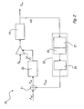
- the reference digital power P ref is fed to the summation node 11 along with the measured power P meas .
- the measured power P meas is subtracted from the reference digital power P ref in order to obtain the error signal P err .
- the error signal P err is then fed into a loop filter 22.
- the filtered error signal P f from the loop filter 22 is sent as a control signal to a variable gain amplifier 23 that receives at its input the input signal S in .
- fine tuning may be needed in order to optimize performance in a number of different fading conditions.
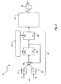
- a logic circuit is provided downstream of the summation node 24.
- This logic circuit includes a first data register 34 followed by a second data register 36.
- a control circuit 33 controls a reset input RST of the first data register 34 and an enable input EN of the second data register 36.
- the output of the data register 34 is fed to the data register 36 and to the summing node 24. This is done in order to accumulate the values of the variable ⁇ up to the moment the control circuit 33 enables feeding the accumulated value through the data register 36 to a look up table that embodies the module for calculating the power value from the threshold crossing rate 29.
- thresholds may in fact be any number.
- the power measurement block 35 is then substantially identical to the block 25 for the single threshold method shown in figure 3 , with the exception of a look up table 39, that implements the inverse of multithreshold function f Multi from equation (12).
- the look up table 39 however has the same size of the look up table 29 for the single threshold.
- Circuit complexity and hardware requirements at the receiver are strongly reduced due to absence of multipliers. Savings in the order of 55% of the chip area in the single threshold case, and 30% in the multithreshold case can be achieved in comparison with the conventional implementation, as shown for instance in figure 1 . Such a reduction also involves a reduction in power consumption at the receiver.
- the primary field of application of the arrangement disclosed herein are devices where the gain of an incoming signal must be controlled, a typical case in point being receivers for mobile telecommunications, such as receivers for satellite and terrestrial mobile telecommunications system according to e.g. GSM, UMTS, CDMA2000, IS95 o WBCDMA standards.
- mobile telecommunications such as receivers for satellite and terrestrial mobile telecommunications system according to e.g. GSM, UMTS, CDMA2000, IS95 o WBCDMA standards.
Landscapes
- Engineering & Computer Science (AREA)
- Theoretical Computer Science (AREA)
- Circuits Of Receivers In General (AREA)
- Control Of Amplification And Gain Control (AREA)
Claims (20)
- Verfahren zur automatischen Verstärkungsregelung, bei dem ein Verstärkungs-geregeltes Ausgangssignal (x(t), Sout) aus einem Eingangssignal (Sin) erzeugt wird, wobei das Verfahren den Schritt beinhaltet, in dem die Leistung (Pmeas) des Ausgangssignals (x(t), Sout) gemessen wird,
wobei der Vorgang des Messens der Leistung des Ausgangssignals (x(t), Sout) folgende Schritte beinhaltet:- Vorgeben von mindestens einem Leistungsschwellenwert;- Messen einer Rate von Kreuzungen, welche die Anzahl von Malen angibt, mit denen das geregelte Ausgangssignal (x(t), Sout) den Leistungsschwellenwert kreuzt, über ein spezielles Betrachtungsfenster;- Ableiten des gemessenen Leistungswerts (Pmeas, σ2) aus der Rate von Kreuzungen, wobei der Schritt des Ableitens des gemessenen Leistungswerts (Pmeas, σ2) auf der Basis einer Rate erfolgt, die durch Akkumulieren einer Anzahl von Kreuzungen und durch Berechnen der Rate als statistischen Erwartungswert anhand der Anzahl von Kreuzungen gemessen wird,dadurch gekennzeichnet, dass der Schritt des Ableitens des gemessenen Leistungswerts (Pmeas, σ2) ferner das Anwenden von mindestens einer Schwellenfunktion an dem statistischen Erwartungswert beinhaltet, um die gemessene Leistung (σ2) zu erhalten. - Verfahren nach Anspruch 1,
dadurch gekennzeichnet, dass es folgende Schritte beinhaltet:- Bereitstellen eines Referenz-Leistungswerts (Pref),- Subtrahieren der gemessenen Leistung (Pmeas) von einem derartigen Referenz-Leistungswert (Pref), um ein Fehlersignal (Perr, Pf) zu erhalten;- Mischen des Eingangssignals (Sin) mit dem Fehlersignal (Perr, Pf); und- Ausführen einer Analog/Digital-Umwandlung an dem Resultat des Mischvorgangs, um ein Verstärkungs-geregeltes Ausgangssignal (x(t), Sout) zu erhalten. - Verfahren nach Anspruch 1,
dadurch gekennzeichnet, dass die Schwellenfunktion eine inverse Fehlerfunktion beinhaltet. - Verfahren nach Anspruch 1,
dadurch gekennzeichnet, dass es das Vorgeben von mehreren Schwellenwerten sowie das Anwenden einer Mehrfachschwellenfunktion an dem statistischen Erwartungswert beinhaltet, um die gemessene Leistung (σ2) zu erhalten. - Verfahren nach Anspruch 1,
dadurch gekennzeichnet, dass die Schwellenfunktion unter Abrufung von Werten in einer Nachschlagetabelle (29, 39) ausgewertet wird. - Verfahren nach Anspruch 2,
dadurch gekennzeichnet, dass es den Schritt des Filterns des Fehlersignals (Perr) durch ein Schleifenfilter (22) vor dem Mischen mit dem Eingangssignal (Sin) beinhaltet. - Verfahren nach Anspruch 2,
dadurch gekennzeichnet, dass der Vorgang des Mischens des Fehlersignals (Perr, Pf) mit dem Eingangssignal (Sin) unter Verstärkung des Eingangssignals (Sin) mit einer variablen Verstärkungsfunktion des Fehlersignals (Perr, Pf) ausgeführt wird. - Verfahren nach einem der vorausgehenden Ansprüche,
dadurch gekennzeichnet, dass es ferner den Schritt des Umwandelns der gemessenen Leistung von einem linearen Wert in einen logarithmischen Wert beinhaltet. - Verfahren nach einem der vorausgehenden Ansprüche,
dadurch gekennzeichnet, dass es den Schritt des Auswählens des Eingangssignals (Sin) als empfangenes Signal in einem Telekommunikationssystem beinhaltet. - Automatische Verstärkungsregelungsvorrichtung, bei der ein Verstärkungs-geregeltes Ausgangssignal (x(t), Sout) aus einem Eingangssignal (Sin) erzeugt wird, wobei die Vorrichtung ein Leistungmessungsmodul (25, 35) zum Messen der Leistung (Pmeas) des Ausgangssignals (x(t), Sout) aufweist, wobei das Leistungsmessungsmodul (25, 35) Schaltungseinrichtungen aufweist, die für mindestens einen Leistungsschwellenwert empfindlich sind; wobei die Schaltungseinrichtungen mindestens ein Modul (27; 37) beinhalten zum Messen einer Rate von Kreuzungen, welche die Anzahl von Malen angibt, mit denen das geregelte Ausgangssignal (x(t), Sout) den Leistungsschwellenwert kreuzt, über ein spezielles Betrachtungsfenster, sowie mindestens ein weiteres Modul (29; 39) beinhalten, um aus der Rate von Kreuzungen den gemessenen Leistungswert (Pmeas, σ2) abzuleiten, wobei das mindestens eine Modul (27; 37) zum Messen der Rate von Kreuzungen ein Register zum Akkumulieren einer Anzahl der Kreuzungen und zum Berechnen der Rate als statistischen Erwartungswert anhand der Anzahl von Kreuzungen aufweist,
dadurch gekennzeichnet, dass das mindestens eine weitere Modul (29; 39) zum Ableiten des gemessenen Leistungswerts (Pmeas, σ2) mindestens einen Schwellenwertkomparator zum Anwenden einer Schwellenfunktion an dem statistischen Erwartungswert aufweist, um die gemessene Leistung (σ2) zu erhalten. - Vorrichtung nach Anspruch 10,
dadurch gekennzeichnet, dass sie Folgendes aufweist:- einen Summier-Knotenpunkt (11) zum Subtrahieren der gemessenen Leistung (Pmeas) von einem Referenz-Leistungswert (Pref), um ein Fehlersignal (Perr, Pf) zu erhalten;- einen Mischer-Knotenpunkt (13, 23) zum Mischen des Eingangssignals (Sin) mit dem Fehlersignal (Perr, Pf); und- einen Analog/Digital-Wandler (14) zum Umwandeln des Resultats des Mischvorgangs, um ein Verstärkungs-geregeltes Ausgangssignal (x(t), Sout) zu erhalten. - Vorrichtung nach Anspruch 10,
dadurch gekennzeichnet, dass der mindestens eine Schwellenwertkomparator die Schwellenfunktion als inverse Fehlerfunktion implementiert. - Vorrichtung nach Anspruch 10,
dadurch gekennzeichnet, dass das mindestens eine weitere Modul (29; 39) zum Ableiten des gemessenen Leistungswerts (Pmeas, σ2) mehrere Schwellenwertkomparatoren zum Anwenden einer Mehrfachschwellenfunktion an dem statistischen Erwartungswert aufweist, um die gemessene Leistung zu erhalten. - Vorrichtung nach Anspruch 10,
dadurch gekennzeichnet, dass sie eine Nachschlagetabelle (29, 39) aufweist, die Werte für die Schwellenfunktion enthält. - Vorrichtung nach Anspruch 11,
dadurch gekennzeichnet, dass sie ein Schleifenfilter (22) aufweist, um das Fehlersignal (Perr) zu filtern, bevor das Fehlersignal mit dem Eingangssignal (Sin) gemischt wird. - Vorrichtung nach Anspruch 11,
dadurch gekennzeichnet, dass der Mischer-Knotenpunkt (13, 23) dafür konfiguriert ist, das Fehlersignal (Perr, Pf) mit dem Eingangssignal (Sin) unter Verstärkung des Eingangssignals (Sin) mit einer variablen Verstärkungsfunktion des Fehlersignals (Perr, Pf) zu verstärken. - Vorrichtung nach einem der Ansprüche 10 bis 16,
dadurch gekennzeichnet, dass sie einen Linear-Logarithmisch-Wandler zum Umwandeln der gemessenen Leistung von einem linearen Wert in einen logarithmischen Wert aufweist. - Vorrichtung nach einem der Ansprüche 10 bis 17 in Form eines Empfängers in einem Telekommunikationssystem.
- Vorrichtung nach einem der Ansprüche 10 bis 17 in Form eines Empfängers für satellitengestützte und terrestrische mobile Telekommunikationssysteme nach einem der Standards GSM, UMTS, CDMA2000, IS95 o WBCDMA.
- Computerprogramm, das sich direkt in den Speicher eines Computers laden lässt und Softwarecodebereiche aufweist, die das Verfahren gemäß einem der Ansprüche 1 bis 9 ausführen, wenn das Programm auf einem Computer läuft.
Priority Applications (3)
| Application Number | Priority Date | Filing Date | Title |
|---|---|---|---|
| DE60331728T DE60331728D1 (de) | 2003-07-15 | 2003-07-15 | Verfahren zur automatischen Verstärkungsregelung, beispielsweise in einem Telekommunikationssystem, Vorrichtung und Computerprogramm hierfür |
| EP03354064A EP1499014B1 (de) | 2003-07-15 | 2003-07-15 | Verfahren zur automatischen Verstärkungsregelung, beispielsweise in einem Telekommunikationssystem, Vorrichtung und Computerprogramm hierfür |
| US10/888,088 US7447283B2 (en) | 2003-07-15 | 2004-07-09 | Method for automatic gain control, for instance in a telecommunication system, device and computer program product therefor |
Applications Claiming Priority (1)
| Application Number | Priority Date | Filing Date | Title |
|---|---|---|---|
| EP03354064A EP1499014B1 (de) | 2003-07-15 | 2003-07-15 | Verfahren zur automatischen Verstärkungsregelung, beispielsweise in einem Telekommunikationssystem, Vorrichtung und Computerprogramm hierfür |
Publications (2)
| Publication Number | Publication Date |
|---|---|
| EP1499014A1 EP1499014A1 (de) | 2005-01-19 |
| EP1499014B1 true EP1499014B1 (de) | 2010-03-17 |
Family
ID=33462267
Family Applications (1)
| Application Number | Title | Priority Date | Filing Date |
|---|---|---|---|
| EP03354064A Expired - Lifetime EP1499014B1 (de) | 2003-07-15 | 2003-07-15 | Verfahren zur automatischen Verstärkungsregelung, beispielsweise in einem Telekommunikationssystem, Vorrichtung und Computerprogramm hierfür |
Country Status (3)
| Country | Link |
|---|---|
| US (1) | US7447283B2 (de) |
| EP (1) | EP1499014B1 (de) |
| DE (1) | DE60331728D1 (de) |
Families Citing this family (4)
| Publication number | Priority date | Publication date | Assignee | Title |
|---|---|---|---|---|
| US8548105B2 (en) * | 2008-08-05 | 2013-10-01 | Qualcomm Incorported | Joint time-frequency automatic gain control for wireless communication |
| IT1398155B1 (it) * | 2009-06-30 | 2013-02-14 | St Microelectronics Srl | Dispositivo elettronico per ricevere un segnale a radio-frequenza |
| WO2011068489A1 (en) * | 2009-12-01 | 2011-06-09 | Thomson Licensing | Software wideband automatic gain control |
| CN102316567A (zh) * | 2011-08-02 | 2012-01-11 | 京信通信系统(中国)有限公司 | 数字自动增益控制方法及系统 |
Family Cites Families (9)
| Publication number | Priority date | Publication date | Assignee | Title |
|---|---|---|---|---|
| IT1190872B (it) * | 1982-06-17 | 1988-02-24 | Sgs Microelettronica Spa | Sistema di amplificazione audio con incremento della potenza media di ascolto |
| US5563916A (en) * | 1995-06-05 | 1996-10-08 | Hitachi America, Ltd. | Apparatus and method for varying the slew rate of a digital automatic gain control circuit |
| US5901173A (en) * | 1996-12-09 | 1999-05-04 | Raytheon Company | Noise Estimator |
| US6324387B1 (en) * | 1998-12-29 | 2001-11-27 | Philips Electronics N.A. Corp. | LNA control-circuit for receive closed loop automatic gain control |
| US6314278B1 (en) * | 1998-12-30 | 2001-11-06 | Uniden America Corporation | Adjusting gain in a receiver using received signal sample values |
| US6668027B1 (en) * | 1999-03-02 | 2003-12-23 | Hitachi America, Ltd. | Self adjusting automatic gain control (AGC) power reference level circuit |
| US6744838B1 (en) * | 2000-08-24 | 2004-06-01 | National Semiconductor Corporation | PLL lock detector |
| US6766153B2 (en) * | 2001-04-02 | 2004-07-20 | Itran Communications Ltd. | Dynamic automatic gain control circuit employing kalman filtering |
| KR100830495B1 (ko) * | 2001-12-29 | 2008-05-21 | 엘지전자 주식회사 | 도플러 천이 추정 방법 및 이를 이용한 데이터 전송 방법 |
-
2003
- 2003-07-15 DE DE60331728T patent/DE60331728D1/de not_active Expired - Lifetime
- 2003-07-15 EP EP03354064A patent/EP1499014B1/de not_active Expired - Lifetime
-
2004
- 2004-07-09 US US10/888,088 patent/US7447283B2/en not_active Expired - Lifetime
Also Published As
| Publication number | Publication date |
|---|---|
| DE60331728D1 (de) | 2010-04-29 |
| EP1499014A1 (de) | 2005-01-19 |
| US7447283B2 (en) | 2008-11-04 |
| US20050031057A1 (en) | 2005-02-10 |
Similar Documents
| Publication | Publication Date | Title |
|---|---|---|
| US7046749B2 (en) | Narrowband gain control of receiver with digital post filtering | |
| CA2188446C (en) | Method and apparatus for automatic gain control in a digital receiver | |
| EP0812064B1 (de) | Verfahren und System zur automatischen Verstärkungsregelung beim Empfang | |
| CA2051982C (en) | Automatic gain control apparatus and method | |
| US8285239B2 (en) | Receiver second order intermodulation correction system and method | |
| CN102668421B (zh) | 用于测量接收器的延迟、增益和相位估计的方法和包括该测量接收器的发射器 | |
| US7929650B2 (en) | AGC for narrowband receivers | |
| US6192226B1 (en) | Carrier squelch processing system and apparatus | |
| US7336937B2 (en) | Compensation of a DC offset in a receiver | |
| EP2259424B1 (de) | Automatische Verstärkungsregelung mit Regelschleifeverstärkungssteuerung | |
| EP1499014B1 (de) | Verfahren zur automatischen Verstärkungsregelung, beispielsweise in einem Telekommunikationssystem, Vorrichtung und Computerprogramm hierfür | |
| US7277510B1 (en) | Adaptation algorithm based on signal statistics for automatic gain control | |
| US9325359B2 (en) | Radiofrequency signal setting reaching a condition of jamming or clipping | |
| EP1296449B1 (de) | Automatische Verstärkungsregelung | |
| JPH08181554A (ja) | 自動利得制御回路を備えたディジタル無線通信装置 | |
| US8081942B1 (en) | Method and apparatus for muting based on a constant modulus indication | |
| US6246728B1 (en) | Apparatus for suppressing interfering DC component shifts in a radio receiver of the direct conversion type, and a corresponding method suppression | |
| US20070165703A1 (en) | Method and apparatus for robust automatic frequency control in cdma systems with constant pilot signals | |
| KR100314921B1 (ko) | 고속데이터전송을위한위성버스트모뎀에서agc회로및그방법 | |
| KR101015716B1 (ko) | 이동통신 시스템에서 이동 단말의 수신 장치 및 신호 수신방법 | |
| JPH1141068A (ja) | ディジタル自動周波数制御回路 | |
| CN101283505A (zh) | 无线通信系统中计算时变sir方法及装置 | |
| HK1011118B (en) | Method and apparatus for automatic gain control in a digital receiver |
Legal Events
| Date | Code | Title | Description |
|---|---|---|---|
| PUAI | Public reference made under article 153(3) epc to a published international application that has entered the european phase |
Free format text: ORIGINAL CODE: 0009012 |
|
| AK | Designated contracting states |
Kind code of ref document: A1 Designated state(s): AT BE BG CH CY CZ DE DK EE ES FI FR GB GR HU IE IT LI LU MC NL PT RO SE SI SK TR |
|
| AX | Request for extension of the european patent |
Extension state: AL LT LV MK |
|
| 17P | Request for examination filed |
Effective date: 20050316 |
|
| AKX | Designation fees paid |
Designated state(s): DE FR GB IT |
|
| 17Q | First examination report despatched |
Effective date: 20080605 |
|
| GRAP | Despatch of communication of intention to grant a patent |
Free format text: ORIGINAL CODE: EPIDOSNIGR1 |
|
| RIN1 | Information on inventor provided before grant (corrected) |
Inventor name: SERRATORE, ALBERTO Inventor name: SALURSO, ELENA Inventor name: PIAZZESE, NICOLO IVAN Inventor name: MESSINA, ETTORE Inventor name: LIPPOLIS, GIUSEPPE Inventor name: GALLUZZO, AGOSTINO |
|
| GRAS | Grant fee paid |
Free format text: ORIGINAL CODE: EPIDOSNIGR3 |
|
| GRAA | (expected) grant |
Free format text: ORIGINAL CODE: 0009210 |
|
| AK | Designated contracting states |
Kind code of ref document: B1 Designated state(s): DE FR GB IT |
|
| REG | Reference to a national code |
Ref country code: GB Ref legal event code: FG4D |
|
| RAP2 | Party data changed (patent owner data changed or rights of a patent transferred) |
Owner name: STMICROELECTRONICS SRL Owner name: STMICROELECTRONICS S.A. |
|
| REF | Corresponds to: |
Ref document number: 60331728 Country of ref document: DE Date of ref document: 20100429 Kind code of ref document: P |
|
| PLBE | No opposition filed within time limit |
Free format text: ORIGINAL CODE: 0009261 |
|
| STAA | Information on the status of an ep patent application or granted ep patent |
Free format text: STATUS: NO OPPOSITION FILED WITHIN TIME LIMIT |
|
| 26N | No opposition filed |
Effective date: 20101220 |
|
| GBPC | Gb: european patent ceased through non-payment of renewal fee |
Effective date: 20100715 |
|
| PG25 | Lapsed in a contracting state [announced via postgrant information from national office to epo] |
Ref country code: IT Free format text: LAPSE BECAUSE OF FAILURE TO SUBMIT A TRANSLATION OF THE DESCRIPTION OR TO PAY THE FEE WITHIN THE PRESCRIBED TIME-LIMIT Effective date: 20100317 |
|
| REG | Reference to a national code |
Ref country code: FR Ref legal event code: ST Effective date: 20110331 |
|
| PG25 | Lapsed in a contracting state [announced via postgrant information from national office to epo] |
Ref country code: FR Free format text: LAPSE BECAUSE OF NON-PAYMENT OF DUE FEES Effective date: 20100802 |
|
| PG25 | Lapsed in a contracting state [announced via postgrant information from national office to epo] |
Ref country code: GB Free format text: LAPSE BECAUSE OF NON-PAYMENT OF DUE FEES Effective date: 20100715 |
|
| REG | Reference to a national code |
Ref country code: DE Ref legal event code: R081 Ref document number: 60331728 Country of ref document: DE Owner name: FRANCE BREVETS, FR Free format text: FORMER OWNERS: STMICROELECTRONICS S.A., MONTROUGE, FR; STMICROELECTRONICS S.R.L., AGRATE BRIANZA, IT Ref country code: DE Ref legal event code: R081 Ref document number: 60331728 Country of ref document: DE Owner name: STMICROELECTRONICS INTERNATIONAL N.V., NL Free format text: FORMER OWNERS: STMICROELECTRONICS S.A., MONTROUGE, FR; STMICROELECTRONICS S.R.L., AGRATE BRIANZA, IT |
|
| REG | Reference to a national code |
Ref country code: DE Ref legal event code: R082 Ref document number: 60331728 Country of ref document: DE Representative=s name: CASALONGA & PARTNERS, DE Ref country code: DE Ref legal event code: R081 Ref document number: 60331728 Country of ref document: DE Owner name: FRANCE BREVETS, FR Free format text: FORMER OWNER: STMICROELECTRONICS INTERNATIONAL N.V., SCHIPHOL, NL |
|
| REG | Reference to a national code |
Ref country code: DE Ref legal event code: R082 Ref document number: 60331728 Country of ref document: DE |
|
| PGFP | Annual fee paid to national office [announced via postgrant information from national office to epo] |
Ref country code: DE Payment date: 20210622 Year of fee payment: 19 |
|
| REG | Reference to a national code |
Ref country code: DE Ref legal event code: R119 Ref document number: 60331728 Country of ref document: DE |
|
| PG25 | Lapsed in a contracting state [announced via postgrant information from national office to epo] |
Ref country code: DE Free format text: LAPSE BECAUSE OF NON-PAYMENT OF DUE FEES Effective date: 20230201 |