EP1499072A2 - Procédé pour la transmission de traffic d' un segment de réseau local à travers un dispositif de pontage - Google Patents
Procédé pour la transmission de traffic d' un segment de réseau local à travers un dispositif de pontage Download PDFInfo
- Publication number
- EP1499072A2 EP1499072A2 EP04016719A EP04016719A EP1499072A2 EP 1499072 A2 EP1499072 A2 EP 1499072A2 EP 04016719 A EP04016719 A EP 04016719A EP 04016719 A EP04016719 A EP 04016719A EP 1499072 A2 EP1499072 A2 EP 1499072A2
- Authority
- EP
- European Patent Office
- Prior art keywords
- plc
- lan
- mac
- bridge
- station
- Prior art date
- Legal status (The legal status is an assumption and is not a legal conclusion. Google has not performed a legal analysis and makes no representation as to the accuracy of the status listed.)
- Granted
Links
- 238000000034 method Methods 0.000 title claims abstract description 46
- 238000004891 communication Methods 0.000 claims abstract description 20
- 230000005540 biological transmission Effects 0.000 claims abstract description 11
- 230000004044 response Effects 0.000 description 11
- 101100048435 Caenorhabditis elegans unc-18 gene Proteins 0.000 description 7
- 238000005516 engineering process Methods 0.000 description 6
- 230000008569 process Effects 0.000 description 5
- 101100520231 Caenorhabditis elegans plc-3 gene Proteins 0.000 description 3
- 230000006870 function Effects 0.000 description 2
- 230000009471 action Effects 0.000 description 1
- 230000002776 aggregation Effects 0.000 description 1
- 238000004220 aggregation Methods 0.000 description 1
- 230000006872 improvement Effects 0.000 description 1
- 238000002372 labelling Methods 0.000 description 1
- 238000012986 modification Methods 0.000 description 1
- 230000004048 modification Effects 0.000 description 1
- 230000005641 tunneling Effects 0.000 description 1
Images


Classifications
-
- H—ELECTRICITY
- H04—ELECTRIC COMMUNICATION TECHNIQUE
- H04L—TRANSMISSION OF DIGITAL INFORMATION, e.g. TELEGRAPHIC COMMUNICATION
- H04L61/00—Network arrangements, protocols or services for addressing or naming
- H04L61/50—Address allocation
- H04L61/5038—Address allocation for local use, e.g. in LAN or USB networks, or in a controller area network [CAN]
-
- H—ELECTRICITY
- H04—ELECTRIC COMMUNICATION TECHNIQUE
- H04B—TRANSMISSION
- H04B2203/00—Indexing scheme relating to line transmission systems
- H04B2203/54—Aspects of powerline communications not already covered by H04B3/54 and its subgroups
- H04B2203/5429—Applications for powerline communications
- H04B2203/5445—Local network
Definitions
- This invention relates to power line networks, and specifically to a method of routing traffic within, onto, and off of a power line based network.
- MAC media access control
- PLC non-power line communication
- a PLC bridge device emulates, to external LANs, the general broadcast nature of LANs, such as Ethernet, when communication is initiated with any station on the PLC LAN side of the PLC bridge.
- LEO ATM LAN Emulation
- This reference describes a coordination device, as in PLC, to distribute end station information, but only PLC station information is distributed, rather than information on all end stations, e.g. , the bridging tables.
- a single connection between ATM nodes is used to carry all bridged traffic.
- the reference describes service to end stations only off of the ATM network.
- Patent Application WO0076122 for LAN emulation using paired unicast and broadcast virtual connections describes bridges which use internal multicast to distribute bridged broadcast and bridged "unknown" packets as part of a learning process.
- the bridges use the information from the broadcasted packets to determine which unicast connection to use.
- This method uses a single connection to forward frames within the bridged LAN.
- Japanese 04107029 for System for connection between local area networks describes a system to learn of external (bridged) stations at the bridges and store that information locally, and a method to communicate to ingress nodes, wherein an egress node has an end station on one of its ports.
- a method of controlling packet transmission in a power line communication (PLC)-based local area network including providing a PLC control coordinator in the PLC LAN for managing allocation of PLC LAN resources; and providing, for any packet traversing the PLC LAN, a destination station MAC address, a source station MAC address, and a temporary equipment identifier (TEI) for the transmitting PLC station.
- PLC power line communication
- LAN local area network
- Another object of the invention is to provide a PLC bridge interconnection station attached to separate physical LANs such that the stations are unaware that they are communicating with different LANs.
- This invention provides a method of interworking packets received at the edge of a PLC network by PLC MAC bridges so that packets may efficiently traverse between the PLC LAN and differing network technologies.
- a PLC bridge interconnection station is attached to separate physical LANs such that the other stations on the LAN are unaware that they are communicating over differing LAN technologies.
- the invention provides a method for bridging media access control (MAC) packets onto, off of, or across a power line communication (PLC) local area network (LAN) segment.
- PLC power line communication
- the method of the invention specifies the transfer of information elements to the terminating stations on the PLC LAN so that subsequent transfers of bearer, or user data packet, traffic across the PLC LAN use identical encoding, regardless of the user data packet traffic's bridging requirements.
- the bridging method of the invention stores information about source and destination stations for a connection at a PLC bridge device. This local store of end-station information allows the PLC bridge to properly interwork packets on or off of the PLC LAN, without the necessity of embedding the information in individual packets.
- the PLC LAN of the method of the invention uses temporary equipment identifiers (TEI) in place of MAC addresses to reduce the amount of overhead in sending data packets over a PLC LAN.
- TEIs are only valid within the confines of the PLC LAN.
- Data packets which are received from non-PLC LANs, or which are to be sent over non-PLC LANs, must be modified by a PLC device, e.g. , a PLC MAC bridge, at the edge of the PLC LAN to be compatible with the non-PLC LAN.
- a PLC MAC bridge device acting in concert with a PLC Central Coordinator (PLC CC), manages the assignment of TEIs, bridging tables, and ConnectionID to enable the proper labeling of data packets for transmission over PLC and non-PLC LANs.
- PLC CC PLC Central Coordinator
- the invention includes:
- a bridge device which caches the source TEI and source 48-bit MAC address of all broadcast data packets received from other bridge devices on the same PLC LAN.
- a PLC MAC bridge which does not establish a connection for bridged traffic until traffic from a source station is received for a destination station where the destination station's source TEI and source 48-bit MAC address are cached in the bridge. This eliminates the need to set up connections between bridges that may not service the destination station.
- the Central Coordinator (PLC CC) in the PLC LAN which manages the allocation of PLC LAN resources to bridging connections.
- the full 48-bit MAC addresses are not transmitted as part of the MAC header for bridged packets.
- the PLC bridge devices interwork the bridged packets between the PLC LAN and any non-PLC LAN, such that TEIs are utilized only in the PLC LAN and 48-bit MAC addresses are used outside the PLC LAN.
- the 48-bit MAC addresses are transmitted with every bridged packet across the PLC LAN.
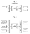
- a MAC, or Layer 2 bridge is a device which allows the interconnection of stations attached to separate physical LANs, as shown in Prior Art Fig. 1, such that protocol layers above Layer 2 are unaware that the stations are communicating from different LANs across the MAC bridge.
- the presence of a MAC bridge may lead to differences in the quality of service (QoS) provided by the MAC sub-layer and it is these QoS differences which may render MAC bridge operation "visible" to upper protocol layers, whereas such operations should be fully transparent to upper protocol layers.
- QoS quality of service
- MAC bridging devices in a local area network are generally transparent to users and administrators of the LAN in that they generally do not require any configuration or setup, except for the physical connection of the bridged LANs to the bridge's ports. Because of the lack of administrative input, MAC bridges must determine their environment from the traffic observed by the bridge on the bridge ' s LAN ports. MAC bridges do not look at the user data contained in packets, but are limited to interpreting only a few packet information fields, such as packet length, source MAC address, and the destination MAC address. Given a received packet's source MAC address and received LAN port, a MAC bridge builds a "bridging table". A MAC bridge determines which LAN port is to be used to transmit a received packet by referencing the bridging table entry with a source MAC address, and its associated port, which matches the destination MAC address in a received packet.
- the bridge does not normally interconnect different PLC LANs, but rather interconnects a PLC LAN to a different LAN technology, such as Ethernet or 802.11 wireless.
- a PLC LAN user data packet traffic across the PLC network is carried across point-to-point connections setup by a PLC CC. These connections are bi-directional, point-to-point communication links across the PLC LAN, with LAN resources allocated to the connection by the PLC CC.
- the PLC LAN does not utilize a MAC packet structure which carries the source and destination MAC addresses, but rather uses a more efficient MAC header, which contains a ConnectionID, which PLC stations may use to determine the source and destination stations for the packet.
- the connection-oriented nature of this PLC LAN, and the special MAC packet structure of PLC packets, requires that PLC bridging devices interwork packets which are bridged onto or off of the PLC LAN.
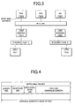
- Fig. 3 and Table 1 are provided as an example of a network configuration in operating the method of the invention.
- PC1 and PC4 are connected to different Ethernet LANS, Ethernet LAN 1 and Ethernet LAN 2, which are bridged across the PLC LAN.
- Bridge6 and Bridge8 are the two MAC bridging devices on the PLC LAN which connect the PLC LAN to Ethernet LAN 1 and Ethernet LAN 2, respectively.
- PC2, PC3 and the PLC CC are stations on the PLC LAN along with Bridge6 and Bridge8.
- Table 1 identifies addresses of stations shown in Fig. 3.
- IP addresses are actually 32 bits wide, and are usually depicted as four, eight-bit decimal numbers, separated by a period e.g ., 192.168.5.207. In this example, however, an IP address is shown as only a single number preceded by a period.
- MAC addresses are normally 48 bits wide, however, in this example, the MAC addresses are shown as numbers between 101 and 109.
- the TEIs for PLC stations in this example are assigned numbers between 2 and 8. Addresses assigned in Fig.
- the interworking of packets from a non-PLC LAN by a bridge device includes the re-addressing of the packet by replacing the source 48-bit MAC address and the designation 48-bit MAC address with the ConnectionID, which is contained in the ConnectionID field in the MAC Header.
- the interworking includes removing the PLC MAC Header and forming the LAN MAC Header containing the source and destination 48-bit MAC addresses.
- each PLC station which are on the PLC LAN are aware of all other active stations on the PLC LAN.
- the information available about each PLC station includes its TEI and 48-bit MAC address.
- the source TEI is included in the broadcast structure, which may carry more than one broadcast packet, to identify the transmitting device because the ConnectionID has a value BCAST, and cannot, therefor, be used to identify the source device.
- the 48-bit MAC address is not included in the MAC packet.
- a bridge device bridges a packet from the PLC network, it uses its local store of the 48-bit source and destination MAC addresses to interwork the packet onto the non-PLC LAN.
- packets that are broadcast on the PLC LAN contain three additional information elements not found in unicast packets.
- the three additional information elements are 1) the 48-bit destination MAC address, 2) the source station's 48-bit MAC address, and 3) the upper layer protocol type.
- the source station's TEI must be included in the broadcast packet because this information is normally available to receiving stations by referencing the connection table with the "identifier" field of unicast transmissions. It is not available in the ConnectionID field when the identified field is set to the broadcast value.
- the 48-bit source and destination MAC addresses are included in the broadcast packet so that other bridges on the PLC network can bridge the packet onto non-PLC LANs as shown in Fig. 7 and described later herein.
- the first example is for communication from PLC station to PLC station, with known TEIs and an empty address resolution protocol (ARP) table.
- PLC station PC2 has a data packet, PKT1, which is to be sent to sent to PLC station PC3.
- PKT1 data packet
- PC2 and PC3 are active nodes on the PLC LAN, both stations are aware of each other's 48-bit MAC address and TEI.
- PC3 is assumed to be an inactive station, which means that it's 48-bit MAC address is not in PC2's ARP table.
- PC2 When PC2 discovers that it has no MAC address for the IP address, PC2 uses an address resolution protocol, such as ARP, to locate the destination station's 48-bit MAC address, and then maps the transport protocol (TP) address, which, in this example, is the destination IP address, to the destination MAC address. PC2 thus broadcasts an ARP request to all stations on the PLC LAN.
- ARP address resolution protocol
- a broadcast packet on the PLC LAN must set its ConnectionID to the known broadcast value.
- a broadcast packet on the PLC LAN includes information elements not included in unicast packets transmitted on the PLC LAN. This additional information is the 48-bit destination MAC address, in this case set to the broadcast address used for ARP requests, the source station's 48-bit MAC address, and the upper layer protocol type.
- PLC bridge devices Bridge6 and Bridge8, bridge the ARP broadcast packet from PC2 onto their respective Ethernet LANs.
- the destination station for the ARP packet is within the PLC LAN, so the bridges will not receive a response packet.
- PC3 receives the ARP request packet and determines that it is the destination station for this packet. Because there is no connection established between PC2 and PC3 within the PLC LAN, PC3 initiates a connection setup sequence with the PLC CC and PC2. PC3's action of setting up a connection at this point in the communication setup process anticipates further communications with PC2. If PC2 finds the connection characteristics as requested by PC3 to be unsatisfactory, the channel characteristics may be negotiated to some other setting, at the request of PC2, during the connection setup process, or a new connection may be setup by PC2 at a later time.
- PC2 and PC3 may transmit packets over the newly allocated connection identified as ConnectionID 11 in Fig. 5.
- PC2 send PKT1 to PC3 over the established connection.
- PC3 responds with PKT2 to PC2 over the same connection.
- the second example involves a scenario for communication from a non-PLC station to a PLC station.
- the example illustrates how communication between one station on an Ethernet LAN to another station on a PLC LAN across a PLC MAC bridge device is controlled.
- station PC1 on Ethernet LAN 1 has a packet to send to station PC2, which is connected to the PLC LAN.
- PC1 and PC2 are initially unaware of each other's location or 48-bit MAC address.
- PC1 transmits an ARP request packet on Ethernet LAN 1 which is received by Bridge6.
- Bridge6 bridges the packet onto the PLC LAN by transmitting it on the broadcast connection, ConnectionID BCST in this example.
- the bridge also includes the destination MAC address, in this case the original broadcast address used by PC1, and the 48-bit MAC address of PC1 in the packet transmitted on the PLC LAN.
- Bridge8 All stations connected to the PLC LAN receive the packet transmitted by Bridge6.
- Bridge8 will bridge the ARP broadcast packet from Bridge6 onto its Ethernet LAN.
- the destination station for the ARP packet is within the PLC LAN, therefore, Bridge8 will not receive a response packet.
- PC2 recognizes the packet as meant for it, so it generates an ARP response packet.
- PC2 initiates a connection setup.
- the connection is setup to Bridge6.
- PC2 includes the source 48-bit MAC address of PC1 supplied in the broadcast ARP request packet.
- Bridge6 accepts the connection, the bridge creates a new entry in its connection table with the source 48-bit MAC address, source TEI, and destination 48-bit MAC address, as shown in Table 2.
- Connection table after Example One and Two ConnectionID (ConnID) Forward MAC Forward TEI Reverse MAC Reverse TEI 11 101 2 103 3 12 101 6 102 2
- PC2 transmits the ARP response packet as a unicast transmission to Bridge6 over the connection with ConnectionID 12.
- Bridge6 receives the ARP response packet, it bridges the packet onto its Ethernet LAN.
- Bridge6 removes the PLC MAC layer information, i.e. , length, ConnectionID, and Protocol Sequence Number, and replaces it with Ethernet MAC layer information, which includes the source and destination 48-bit MAC addresses, which the bridge has in its connection table, Table 2.
- the Ethernet source address is set to the MAC address of PC2 and the destination MAC address is set to the MAC address of PC1.
- PC1 When PC1 receives the ARP response from PC2, it updates its ARP tables and then unicasts PKT3 to PC2 on the Ethernet LAN.
- Bridge6 receives all packets transmitted on the Ethernet connected to its Ethernet port and recognizes PKT3 as a packet which it must bridge to PC2 on the PLC LAN.
- Bridge6 looks in its connection table to find a connection entry that matches both the 48-bit source MAC and 48-bit destination MAC addresses. Bridge6 finds the entry in the connection table and transmits the bridged PKT3 over the connection with ConnectionID 12 to PC2.
- PC2 is then able to transmit PKT4 to PC1 in the same manner as the previous ARP response packet.
- the third example involves a scenario for communication from a non-PLC station to a non-PLC station across a PLC LAN.
- a non-PLC station to a non-PLC station across a PLC LAN.
- FIGs. 3 and 7 the communication between one station on an Ethernet LAN and another station on a different Ethernet LAN, bridging across a PLC LAN, is depicted.
- station PC1 on Ethernet LAN 1 has a packet to send to station PC4 on Ethernet LAN 2.
- the two Ethernet LAN segments are bridged together across the PLC LAN.
- the two stations are not aware of each other's location or 48-bit MAC address.
- PC1 starts the messaging sequence by broadcasting the ARP request packet on Ethernet LAN 1.
- Bridge6 bridges the ARP request packet onto the PLC LAN, which request packet is received by all PLC LAN stations.
- Bridge8 bridges the packet from the PLC LAN and to Ethernet LAN 2.
- PC4 is attached to Ethernet LAN 2 and recognizes that it is the destination for this packet.
- Bridge8 When Bridge8 receives the ARP request packet from Bridge6, it caches information about PC1 in its bridging table.
- the information elements it cached about PC1 are its 48-bit MAC address, LAN port on which PC1's packet is received, and the TEI of the PLC station that sent the packet on the PLC LAN, as shown in Table 3.
- PC5 When PC5 receives the ARP request from PC1, it updates its ARP tables and unicasts an ARP response to PC1 on the Ethernet LAN.
- Bridge8 receives all packets transmitted on the Ethernet LAN connected to its Ethernet port. It recognizes the destination MAC address of the ARP response packet as an address for a station which is on the PLC LAN side of the bridge and recognizes that it must bridge the packet onto the PLC LAN.
- Bridge8 sees that its bridging table entry does not specify an existing PLC connection on which to place a packet with that 48-bit MAC address, causing the bridge to initiate a connection setup between Bridge8 and Bridge6, indicated by the Bridge6 TEI specified in the bridging table.
- Bridge6 and Bridge8 make entries in their bridging tables to indicate that the new connection between them carries traffic between PC1 and PC4 over ConnectionID 13, as shown in Tables 4, 5 and 6.
- Bridge6 bridging table after the connection setup Known MAC Address Destination LAN Port Destination TEI Destination ConnID 102 PLC 2 - 103 PLC 3 - 105 PLC 5 - 108 PLC 8 - 101 ENet - - 104 PLC 8 13
- Bridge8 bridging table after the connection setup Known MAC Address Destination LAN Port Destination TEI Destination ConnID 102 PLC 2 - 103 PLC 3 - 105 PLC 5 - 106 PLC 6 - 101 PLC 6 13 104 ENet - - Connection table after example 10.1,10.2, and 10.3 ConnID Forward MAC Forward TEI Reverse MAC Reverse TEI 11 102 2 103 3 12 101 6 102 2 13 101 6 104 8
- Bridge8 bridges the ARP response packet over the PLC LAN to Bridge6 on the connection with ConnectionID 13. Bridge6 then bridges the packet onto the Ethernet LAN, as in Example Two.
- PC1 receives the ARP response packet, it updates its ARP table and proceeds with the transmission of PKT5 on the Ethernet LAN.
- Bridge6 receives PKT5 on its Ethernet port and bridges the packet over the PLC LAN on the connection with ConnectionID 13 to Bridge8.
- Bridge8 then bridges the received PKT5 packet onto Ethernet LAN2, with the destination MAC address set to PC4's 48-bit MAC address. Packet PKT6 is then transmitted by PC4 onto Ethernet LAN 2, bridged by Bridge8 onto the PLC LAN, and then bridged by Bridge6 onto Ethernet LAN 1 to station PC1.
Landscapes
- Engineering & Computer Science (AREA)
- Computer Networks & Wireless Communication (AREA)
- Signal Processing (AREA)
- Small-Scale Networks (AREA)
- Cable Transmission Systems, Equalization Of Radio And Reduction Of Echo (AREA)
Applications Claiming Priority (2)
| Application Number | Priority Date | Filing Date | Title |
|---|---|---|---|
| US622903 | 1990-12-06 | ||
| US10/622,903 US20050013307A1 (en) | 2003-07-17 | 2003-07-17 | Method for bridging traffic on a PLC LAN segment |
Publications (3)
| Publication Number | Publication Date |
|---|---|
| EP1499072A2 true EP1499072A2 (fr) | 2005-01-19 |
| EP1499072A3 EP1499072A3 (fr) | 2007-05-30 |
| EP1499072B1 EP1499072B1 (fr) | 2010-09-08 |
Family
ID=33477139
Family Applications (1)
| Application Number | Title | Priority Date | Filing Date |
|---|---|---|---|
| EP04016719A Expired - Lifetime EP1499072B1 (fr) | 2003-07-17 | 2004-07-15 | Procédé pour l'interconnection de réseaux par courant porteur (PLC) avec d'autres réseaux locaux |
Country Status (4)
| Country | Link |
|---|---|
| US (1) | US20050013307A1 (fr) |
| EP (1) | EP1499072B1 (fr) |
| JP (1) | JP2005039814A (fr) |
| DE (1) | DE602004028991D1 (fr) |
Cited By (3)
| Publication number | Priority date | Publication date | Assignee | Title |
|---|---|---|---|---|
| CN101331689A (zh) * | 2006-02-16 | 2008-12-24 | 三星电子株式会社 | 属于不同plc小区的plc站之间的数据通信方法及其设备 |
| CN104242989A (zh) * | 2013-06-24 | 2014-12-24 | 华为技术有限公司 | 对码方法和装置 |
| WO2015040244A1 (fr) * | 2013-09-23 | 2015-03-26 | Siemens Plc | Système de connexion de dispositifs intelligents dans un bâtiment |
Families Citing this family (17)
| Publication number | Priority date | Publication date | Assignee | Title |
|---|---|---|---|---|
| KR101088007B1 (ko) * | 2004-08-24 | 2011-12-01 | 팬듀트 코포레이션 | 네트워크 관리를 위한 시스템 및 그 방법 |
| CN101080904A (zh) * | 2004-11-09 | 2007-11-28 | 诺基亚公司 | 桥接数据网络通信 |
| US7437140B2 (en) * | 2005-01-21 | 2008-10-14 | Sony Corporation | Power line network bridge |
| WO2007055399A1 (fr) * | 2005-11-10 | 2007-05-18 | Matsushita Electric Industrial Co., Ltd. | Procede et appareil pour courants porteurs en ligne |
| CN1852254A (zh) * | 2006-02-17 | 2006-10-25 | 华为技术有限公司 | 实现mpls报文转发的以太交换设备和方法 |
| TWI307226B (en) * | 2006-02-23 | 2009-03-01 | Ind Tech Res Inst | Multicast packet transmitting method of wireless network |
| KR100941182B1 (ko) | 2008-01-28 | 2010-02-10 | 조승호 | 전력선통신 3상 라우터 시스템 및 그 시스템의 파워패킷전송 방법 |
| KR100941181B1 (ko) | 2008-01-28 | 2010-02-10 | 조승호 | 전력선통신 3상 라우터 |
| US8929396B2 (en) * | 2008-07-07 | 2015-01-06 | Futurewei Technologies, Inc. | Ethernet media access control organization specific extension |
| WO2011150268A1 (fr) | 2010-05-26 | 2011-12-01 | Wirefi Networks, Inc. | Dispositif de réseau à multiples supports de communication |
| JP5557730B2 (ja) * | 2010-12-24 | 2014-07-23 | 株式会社日立製作所 | パケットトランスポート装置 |
| CN103546382B (zh) * | 2013-11-05 | 2016-08-17 | 中国联合网络通信集团有限公司 | 数据处理方法、设备和系统 |
| KR102083802B1 (ko) * | 2013-12-31 | 2020-03-03 | 삼성전자주식회사 | 식기 세척기 및 그 제어 방법 |
| EP3092751A4 (fr) * | 2014-01-06 | 2017-10-18 | Samsung Electronics Co., Ltd. | Procédé et appareil de relais de transmission de paquets et de mise à jour d'informations d'adresse réseau dans un système de communication |
| US9281868B2 (en) | 2014-05-28 | 2016-03-08 | Wirefi Networks, Inc. | Power line communications zoning device |
| US10155479B2 (en) * | 2017-01-09 | 2018-12-18 | Moki Doorstep Corp. | Vehicle door well step apparatus |
| KR102110857B1 (ko) * | 2018-11-14 | 2020-05-13 | 주식회사 퀀텀솔루션 | 게이트웨이를 이용하는 전력망 통신 시스템 및 동작 방법 |
Citations (2)
| Publication number | Priority date | Publication date | Assignee | Title |
|---|---|---|---|---|
| EP1217475A2 (fr) | 2000-12-13 | 2002-06-26 | Lg Electronics Inc. | Appareil et méthode pour commander à distance des appareils ménagers |
| EP1244326A1 (fr) | 2000-11-30 | 2002-09-25 | Mitsubishi Denki Kabushiki Kaisha | Procede d'etablissement de code domestique et systeme de communication par ligne electrique |
Family Cites Families (11)
| Publication number | Priority date | Publication date | Assignee | Title |
|---|---|---|---|---|
| JPH0655826B2 (ja) * | 1989-10-09 | 1994-07-27 | 三菱油化株式会社 | 合成樹脂用模様着色材料およびその製造法並びにそれを用いた合成樹脂成形体 |
| US6016319A (en) * | 1995-10-31 | 2000-01-18 | Lucent Technologies, Inc. | Communications system for transmission of datagram packets over connection-oriented networks |
| US6151324A (en) * | 1996-06-03 | 2000-11-21 | Cabletron Systems, Inc. | Aggregation of mac data flows through pre-established path between ingress and egress switch to reduce number of number connections |
| US6337863B1 (en) * | 1997-01-17 | 2002-01-08 | Alcatel Interworking, Inc. | Seamless communication service with intelligent edge devices |
| US6343083B1 (en) * | 1998-04-09 | 2002-01-29 | Alcatel Usa Sourcing, L.P. | Method and apparatus for supporting a connectionless communication protocol over an ATM network |
| US6728249B2 (en) * | 1998-06-27 | 2004-04-27 | Intel Corporation | System and method for performing cut-through forwarding in an ATM network supporting LAN emulation |
| JP3269523B2 (ja) * | 1998-08-18 | 2002-03-25 | 日本電気株式会社 | 通信方法 |
| JP3214471B2 (ja) * | 1998-12-03 | 2001-10-02 | 日本電気株式会社 | Atm lanエミュレーション・ネットワーク |
| US6295276B1 (en) * | 1999-12-31 | 2001-09-25 | Ragula Systems | Combining routers to increase concurrency and redundancy in external network access |
| US6728261B1 (en) * | 2000-02-07 | 2004-04-27 | Axerra Networks, Ltd. | ATM over IP |
| US6587739B1 (en) * | 2000-09-29 | 2003-07-01 | Sunbeam Products, Inc. | Appliance communication and control system and appliances for use in same |
-
2003
- 2003-07-17 US US10/622,903 patent/US20050013307A1/en not_active Abandoned
-
2004
- 2004-07-08 JP JP2004202016A patent/JP2005039814A/ja active Pending
- 2004-07-15 DE DE602004028991T patent/DE602004028991D1/de not_active Expired - Lifetime
- 2004-07-15 EP EP04016719A patent/EP1499072B1/fr not_active Expired - Lifetime
Patent Citations (2)
| Publication number | Priority date | Publication date | Assignee | Title |
|---|---|---|---|---|
| EP1244326A1 (fr) | 2000-11-30 | 2002-09-25 | Mitsubishi Denki Kabushiki Kaisha | Procede d'etablissement de code domestique et systeme de communication par ligne electrique |
| EP1217475A2 (fr) | 2000-12-13 | 2002-06-26 | Lg Electronics Inc. | Appareil et méthode pour commander à distance des appareils ménagers |
Cited By (4)
| Publication number | Priority date | Publication date | Assignee | Title |
|---|---|---|---|---|
| CN101331689A (zh) * | 2006-02-16 | 2008-12-24 | 三星电子株式会社 | 属于不同plc小区的plc站之间的数据通信方法及其设备 |
| CN104242989A (zh) * | 2013-06-24 | 2014-12-24 | 华为技术有限公司 | 对码方法和装置 |
| CN104242989B (zh) * | 2013-06-24 | 2017-02-08 | 华为技术有限公司 | 对码方法和装置 |
| WO2015040244A1 (fr) * | 2013-09-23 | 2015-03-26 | Siemens Plc | Système de connexion de dispositifs intelligents dans un bâtiment |
Also Published As
| Publication number | Publication date |
|---|---|
| DE602004028991D1 (de) | 2010-10-21 |
| EP1499072B1 (fr) | 2010-09-08 |
| JP2005039814A (ja) | 2005-02-10 |
| EP1499072A3 (fr) | 2007-05-30 |
| US20050013307A1 (en) | 2005-01-20 |
Similar Documents
| Publication | Publication Date | Title |
|---|---|---|
| EP1499072B1 (fr) | Procédé pour l'interconnection de réseaux par courant porteur (PLC) avec d'autres réseaux locaux | |
| US5581552A (en) | Multimedia server | |
| US5600644A (en) | Method and apparatus for interconnecting LANs | |
| US6111876A (en) | VLAN frame format | |
| US5959990A (en) | VLAN frame format | |
| US5752003A (en) | Architecture for managing traffic in a virtual LAN environment | |
| CA2256698C (fr) | Concentration de connexions dans des reseaux de communications commutes | |
| CA2286422C (fr) | Methode et appareil de communication par multidiffusion | |
| US6956824B2 (en) | Extension of link aggregation protocols over the network | |
| US6041358A (en) | Method for maintaining virtual local area networks with mobile terminals in an ATM network | |
| US6189042B1 (en) | LAN internet connection having effective mechanism to classify LAN traffic and resolve address resolution protocol requests | |
| WO1998002821A1 (fr) | Architecture de reseau virtuel pour reseau de base local fonctionnant en mode sans connexion | |
| US20020080800A1 (en) | VLAN data switching method using ARP packet | |
| US5930255A (en) | Method of setting a relaying path in a communication network | |
| EP1022881B1 (fr) | Procédé de routage dans un intranet de bande passante très faible | |
| US7639683B2 (en) | Multicast communication method using layer 2 and 3 switches | |
| US20050044271A1 (en) | Method for allocating a non-data device to a voice vlan object of the invention | |
| JP3560559B2 (ja) | Lanエミュレーションにおけるipサーバの負荷分散装置およびその負荷分散方法 | |
| KR100224318B1 (ko) | 공중망 비동기 전달 모드(atm) 교환시스템에서의랜(lan) 트래픽 처리 방법 | |
| KR100369934B1 (ko) | Mpoa 기반의 3계층 가상랜 시스템 및 제공방법 | |
| JPH10243009A (ja) | スイッチングハブ | |
| JPH1093637A (ja) | ネットワーク間接続装置のルーティング方法 | |
| US20050129048A1 (en) | Method for transmitting multicast data information | |
| JP2000032058A (ja) | 高効率パケットデ―タ伝送ネットワ―クおよびそれに用いられるインタフェ―ス | |
| JPH01103050A (ja) | パケットプロトコル通信装置 |
Legal Events
| Date | Code | Title | Description |
|---|---|---|---|
| PUAI | Public reference made under article 153(3) epc to a published international application that has entered the european phase |
Free format text: ORIGINAL CODE: 0009012 |
|
| AK | Designated contracting states |
Kind code of ref document: A2 Designated state(s): AT BE BG CH CY CZ DE DK EE ES FI FR GB GR HU IE IT LI LU MC NL PL PT RO SE SI SK TR |
|
| AX | Request for extension of the european patent |
Extension state: AL HR LT LV MK |
|
| PUAL | Search report despatched |
Free format text: ORIGINAL CODE: 0009013 |
|
| AK | Designated contracting states |
Kind code of ref document: A3 Designated state(s): AT BE BG CH CY CZ DE DK EE ES FI FR GB GR HU IE IT LI LU MC NL PL PT RO SE SI SK TR |
|
| AX | Request for extension of the european patent |
Extension state: AL HR LT LV MK |
|
| RIC1 | Information provided on ipc code assigned before grant |
Ipc: H04L 12/46 20060101AFI20041101BHEP Ipc: H04L 29/12 20060101ALI20070420BHEP Ipc: H04B 3/54 20060101ALI20070420BHEP |
|
| 17P | Request for examination filed |
Effective date: 20071001 |
|
| 17Q | First examination report despatched |
Effective date: 20071122 |
|
| AKX | Designation fees paid |
Designated state(s): DE FR GB |
|
| GRAP | Despatch of communication of intention to grant a patent |
Free format text: ORIGINAL CODE: EPIDOSNIGR1 |
|
| RTI1 | Title (correction) |
Free format text: METHOD FOR INTERCONNECTING A PLC LAN WITH ANY OTHER NON-PLC LAN |
|
| GRAS | Grant fee paid |
Free format text: ORIGINAL CODE: EPIDOSNIGR3 |
|
| GRAA | (expected) grant |
Free format text: ORIGINAL CODE: 0009210 |
|
| AK | Designated contracting states |
Kind code of ref document: B1 Designated state(s): DE FR GB |
|
| REG | Reference to a national code |
Ref country code: GB Ref legal event code: FG4D |
|
| REF | Corresponds to: |
Ref document number: 602004028991 Country of ref document: DE Date of ref document: 20101021 Kind code of ref document: P |
|
| PLBE | No opposition filed within time limit |
Free format text: ORIGINAL CODE: 0009261 |
|
| STAA | Information on the status of an ep patent application or granted ep patent |
Free format text: STATUS: NO OPPOSITION FILED WITHIN TIME LIMIT |
|
| 26N | No opposition filed |
Effective date: 20110609 |
|
| REG | Reference to a national code |
Ref country code: DE Ref legal event code: R097 Ref document number: 602004028991 Country of ref document: DE Effective date: 20110609 |
|
| REG | Reference to a national code |
Ref country code: FR Ref legal event code: PLFP Year of fee payment: 13 |
|
| REG | Reference to a national code |
Ref country code: DE Ref legal event code: R084 Ref document number: 602004028991 Country of ref document: DE |
|
| REG | Reference to a national code |
Ref country code: GB Ref legal event code: 746 Effective date: 20160728 |
|
| PGFP | Annual fee paid to national office [announced via postgrant information from national office to epo] |
Ref country code: GB Payment date: 20160721 Year of fee payment: 13 Ref country code: DE Payment date: 20160722 Year of fee payment: 13 |
|
| PGFP | Annual fee paid to national office [announced via postgrant information from national office to epo] |
Ref country code: FR Payment date: 20160721 Year of fee payment: 13 |
|
| REG | Reference to a national code |
Ref country code: DE Ref legal event code: R119 Ref document number: 602004028991 Country of ref document: DE |
|
| GBPC | Gb: european patent ceased through non-payment of renewal fee |
Effective date: 20170715 |
|
| REG | Reference to a national code |
Ref country code: FR Ref legal event code: ST Effective date: 20180330 |
|
| PG25 | Lapsed in a contracting state [announced via postgrant information from national office to epo] |
Ref country code: DE Free format text: LAPSE BECAUSE OF NON-PAYMENT OF DUE FEES Effective date: 20180201 Ref country code: GB Free format text: LAPSE BECAUSE OF NON-PAYMENT OF DUE FEES Effective date: 20170715 |
|
| PG25 | Lapsed in a contracting state [announced via postgrant information from national office to epo] |
Ref country code: FR Free format text: LAPSE BECAUSE OF NON-PAYMENT OF DUE FEES Effective date: 20170731 |