EP1499435B1 - Verfahren zum herstellen eines elementes einer chemischen vorrichtung enthaltend ein metallisches haltewerkstück und metallische antikorrosionbeschichtung - Google Patents
Verfahren zum herstellen eines elementes einer chemischen vorrichtung enthaltend ein metallisches haltewerkstück und metallische antikorrosionbeschichtung Download PDFInfo
- Publication number
- EP1499435B1 EP1499435B1 EP02732842A EP02732842A EP1499435B1 EP 1499435 B1 EP1499435 B1 EP 1499435B1 EP 02732842 A EP02732842 A EP 02732842A EP 02732842 A EP02732842 A EP 02732842A EP 1499435 B1 EP1499435 B1 EP 1499435B1
- Authority
- EP
- European Patent Office
- Prior art keywords
- manufacturing
- coating
- brazing
- assembly
- coated
- Prior art date
- Legal status (The legal status is an assumption and is not a legal conclusion. Google has not performed a legal analysis and makes no representation as to the accuracy of the status listed.)
- Expired - Lifetime
Links
Images



Classifications
-
- B—PERFORMING OPERATIONS; TRANSPORTING
- B01—PHYSICAL OR CHEMICAL PROCESSES OR APPARATUS IN GENERAL
- B01J—CHEMICAL OR PHYSICAL PROCESSES, e.g. CATALYSIS OR COLLOID CHEMISTRY; THEIR RELEVANT APPARATUS
- B01J19/00—Chemical, physical or physico-chemical processes in general; Their relevant apparatus
- B01J19/02—Apparatus characterised by being constructed of material selected for its chemically-resistant properties
-
- C—CHEMISTRY; METALLURGY
- C23—COATING METALLIC MATERIAL; COATING MATERIAL WITH METALLIC MATERIAL; CHEMICAL SURFACE TREATMENT; DIFFUSION TREATMENT OF METALLIC MATERIAL; COATING BY VACUUM EVAPORATION, BY SPUTTERING, BY ION IMPLANTATION OR BY CHEMICAL VAPOUR DEPOSITION, IN GENERAL; INHIBITING CORROSION OF METALLIC MATERIAL OR INCRUSTATION IN GENERAL
- C23C—COATING METALLIC MATERIAL; COATING MATERIAL WITH METALLIC MATERIAL; SURFACE TREATMENT OF METALLIC MATERIAL BY DIFFUSION INTO THE SURFACE, BY CHEMICAL CONVERSION OR SUBSTITUTION; COATING BY VACUUM EVAPORATION, BY SPUTTERING, BY ION IMPLANTATION OR BY CHEMICAL VAPOUR DEPOSITION, IN GENERAL
- C23C28/00—Coating for obtaining at least two superposed coatings either by methods not provided for in a single one of groups C23C2/00 - C23C26/00 or by combinations of methods provided for in subclasses C23C and C25C or C25D
- C23C28/02—Coating for obtaining at least two superposed coatings either by methods not provided for in a single one of groups C23C2/00 - C23C26/00 or by combinations of methods provided for in subclasses C23C and C25C or C25D only coatings only including layers of metallic material
- C23C28/021—Coating for obtaining at least two superposed coatings either by methods not provided for in a single one of groups C23C2/00 - C23C26/00 or by combinations of methods provided for in subclasses C23C and C25C or C25D only coatings only including layers of metallic material including at least one metal alloy layer
-
- B—PERFORMING OPERATIONS; TRANSPORTING
- B23—MACHINE TOOLS; METAL-WORKING NOT OTHERWISE PROVIDED FOR
- B23K—SOLDERING OR UNSOLDERING; WELDING; CLADDING OR PLATING BY SOLDERING OR WELDING; CUTTING BY APPLYING HEAT LOCALLY, e.g. FLAME CUTTING; WORKING BY LASER BEAM
- B23K1/00—Soldering, e.g. brazing, or unsoldering
- B23K1/008—Soldering within a furnace
-
- B—PERFORMING OPERATIONS; TRANSPORTING
- B23—MACHINE TOOLS; METAL-WORKING NOT OTHERWISE PROVIDED FOR
- B23K—SOLDERING OR UNSOLDERING; WELDING; CLADDING OR PLATING BY SOLDERING OR WELDING; CUTTING BY APPLYING HEAT LOCALLY, e.g. FLAME CUTTING; WORKING BY LASER BEAM
- B23K1/00—Soldering, e.g. brazing, or unsoldering
- B23K1/012—Soldering with the use of hot gas
-
- B—PERFORMING OPERATIONS; TRANSPORTING
- B23—MACHINE TOOLS; METAL-WORKING NOT OTHERWISE PROVIDED FOR
- B23K—SOLDERING OR UNSOLDERING; WELDING; CLADDING OR PLATING BY SOLDERING OR WELDING; CUTTING BY APPLYING HEAT LOCALLY, e.g. FLAME CUTTING; WORKING BY LASER BEAM
- B23K1/00—Soldering, e.g. brazing, or unsoldering
- B23K1/19—Soldering, e.g. brazing, or unsoldering taking account of the properties of the materials to be soldered
-
- C—CHEMISTRY; METALLURGY
- C23—COATING METALLIC MATERIAL; COATING MATERIAL WITH METALLIC MATERIAL; CHEMICAL SURFACE TREATMENT; DIFFUSION TREATMENT OF METALLIC MATERIAL; COATING BY VACUUM EVAPORATION, BY SPUTTERING, BY ION IMPLANTATION OR BY CHEMICAL VAPOUR DEPOSITION, IN GENERAL; INHIBITING CORROSION OF METALLIC MATERIAL OR INCRUSTATION IN GENERAL
- C23C—COATING METALLIC MATERIAL; COATING MATERIAL WITH METALLIC MATERIAL; SURFACE TREATMENT OF METALLIC MATERIAL BY DIFFUSION INTO THE SURFACE, BY CHEMICAL CONVERSION OR SUBSTITUTION; COATING BY VACUUM EVAPORATION, BY SPUTTERING, BY ION IMPLANTATION OR BY CHEMICAL VAPOUR DEPOSITION, IN GENERAL
- C23C28/00—Coating for obtaining at least two superposed coatings either by methods not provided for in a single one of groups C23C2/00 - C23C26/00 or by combinations of methods provided for in subclasses C23C and C25C or C25D
- C23C28/02—Coating for obtaining at least two superposed coatings either by methods not provided for in a single one of groups C23C2/00 - C23C26/00 or by combinations of methods provided for in subclasses C23C and C25C or C25D only coatings only including layers of metallic material
- C23C28/023—Coating for obtaining at least two superposed coatings either by methods not provided for in a single one of groups C23C2/00 - C23C26/00 or by combinations of methods provided for in subclasses C23C and C25C or C25D only coatings only including layers of metallic material only coatings of metal elements only
-
- C—CHEMISTRY; METALLURGY
- C23—COATING METALLIC MATERIAL; COATING MATERIAL WITH METALLIC MATERIAL; CHEMICAL SURFACE TREATMENT; DIFFUSION TREATMENT OF METALLIC MATERIAL; COATING BY VACUUM EVAPORATION, BY SPUTTERING, BY ION IMPLANTATION OR BY CHEMICAL VAPOUR DEPOSITION, IN GENERAL; INHIBITING CORROSION OF METALLIC MATERIAL OR INCRUSTATION IN GENERAL
- C23C—COATING METALLIC MATERIAL; COATING MATERIAL WITH METALLIC MATERIAL; SURFACE TREATMENT OF METALLIC MATERIAL BY DIFFUSION INTO THE SURFACE, BY CHEMICAL CONVERSION OR SUBSTITUTION; COATING BY VACUUM EVAPORATION, BY SPUTTERING, BY ION IMPLANTATION OR BY CHEMICAL VAPOUR DEPOSITION, IN GENERAL
- C23C28/00—Coating for obtaining at least two superposed coatings either by methods not provided for in a single one of groups C23C2/00 - C23C26/00 or by combinations of methods provided for in subclasses C23C and C25C or C25D
- C23C28/02—Coating for obtaining at least two superposed coatings either by methods not provided for in a single one of groups C23C2/00 - C23C26/00 or by combinations of methods provided for in subclasses C23C and C25C or C25D only coatings only including layers of metallic material
- C23C28/023—Coating for obtaining at least two superposed coatings either by methods not provided for in a single one of groups C23C2/00 - C23C26/00 or by combinations of methods provided for in subclasses C23C and C25C or C25D only coatings only including layers of metallic material only coatings of metal elements only
- C23C28/025—Coating for obtaining at least two superposed coatings either by methods not provided for in a single one of groups C23C2/00 - C23C26/00 or by combinations of methods provided for in subclasses C23C and C25C or C25D only coatings only including layers of metallic material only coatings of metal elements only with at least one zinc-based layer
-
- B—PERFORMING OPERATIONS; TRANSPORTING
- B23—MACHINE TOOLS; METAL-WORKING NOT OTHERWISE PROVIDED FOR
- B23K—SOLDERING OR UNSOLDERING; WELDING; CLADDING OR PLATING BY SOLDERING OR WELDING; CUTTING BY APPLYING HEAT LOCALLY, e.g. FLAME CUTTING; WORKING BY LASER BEAM
- B23K2103/00—Materials to be soldered, welded or cut
- B23K2103/02—Iron or ferrous alloys
- B23K2103/04—Steel or steel alloys
-
- B—PERFORMING OPERATIONS; TRANSPORTING
- B23—MACHINE TOOLS; METAL-WORKING NOT OTHERWISE PROVIDED FOR
- B23K—SOLDERING OR UNSOLDERING; WELDING; CLADDING OR PLATING BY SOLDERING OR WELDING; CUTTING BY APPLYING HEAT LOCALLY, e.g. FLAME CUTTING; WORKING BY LASER BEAM
- B23K2103/00—Materials to be soldered, welded or cut
- B23K2103/02—Iron or ferrous alloys
- B23K2103/04—Steel or steel alloys
- B23K2103/05—Stainless steel
-
- B—PERFORMING OPERATIONS; TRANSPORTING
- B23—MACHINE TOOLS; METAL-WORKING NOT OTHERWISE PROVIDED FOR
- B23K—SOLDERING OR UNSOLDERING; WELDING; CLADDING OR PLATING BY SOLDERING OR WELDING; CUTTING BY APPLYING HEAT LOCALLY, e.g. FLAME CUTTING; WORKING BY LASER BEAM
- B23K2103/00—Materials to be soldered, welded or cut
- B23K2103/08—Non-ferrous metals or alloys
- B23K2103/14—Titanium or alloys thereof
-
- B—PERFORMING OPERATIONS; TRANSPORTING
- B23—MACHINE TOOLS; METAL-WORKING NOT OTHERWISE PROVIDED FOR
- B23K—SOLDERING OR UNSOLDERING; WELDING; CLADDING OR PLATING BY SOLDERING OR WELDING; CUTTING BY APPLYING HEAT LOCALLY, e.g. FLAME CUTTING; WORKING BY LASER BEAM
- B23K35/00—Rods, electrodes, materials, or media, for use in soldering, welding, or cutting
- B23K35/22—Rods, electrodes, materials, or media, for use in soldering, welding, or cutting characterised by the composition or nature of the material
- B23K35/24—Selection of soldering or welding materials proper
- B23K35/30—Selection of soldering or welding materials proper with the principal constituent melting at less than 1550°C
- B23K35/3006—Ag as the principal constituent
Definitions
- the invention relates to devices for handling, storage and treatment of chemicals for the chemical industries. It relates in particular to mixers, treatment devices and conveyors capable of handling highly corrosive products, such as concentrated acids or bases.
- the term "chemical device element” denotes, in a collective manner, the storage enclosures, the tanks, the heat exchangers, the reactors, the mixers, the treatment devices and the routing devices. .
- the invention relates to a method of manufacturing plated products, such as chemical device elements or assembly parts for the manufacture of elements of chemical devices, comprising at least one metal support part and a coating. anti-corrosion metal.
- the chemical device elements most often comprise steel support pieces and an anti-corrosion metallic coating based on "noble" metals, such as titanium, tantalum, nickel, zirconium, a nickel base alloy or stainless steel.
- the elements chemical device can be manufactured by assembling assembly parts, such as plates, previously coated with an anti-corrosion metal coating.
- the anti-corrosion coating may be attached to the support piece in various ways, such as by knurling, explosion (“explosion clad”), hot calendering or simple cladding without junction between the plate and the anti-corrosion coating.
- Some applications such as devices with low internal pressure, require a strong bond between the metal support member and the anticorrosive coating, i.e., a connection which has a high resistance to tearing, so as to avoid the separation between them which could, for example, lead to a collapse of the anti-corrosion coating.
- Knurling, "clad explosion” and calendering make it possible to obtain very strong support / coating bonds, but these techniques can not be used when the thickness of the anti-corrosion coating is less than 0.7 mm.
- Brazing makes it possible to obtain very strong support / coating bonds and to reduce the thickness of the coating.
- Brazing introduces additional difficulties.
- the difference in coefficient of thermal expansion between the substrate and the coating material (for example, the coefficient of expansion of the steel is about twice as high as that of tantalum) leads to the formation of mechanical stresses. These constraints weaken and deform the coating.
- the brazing operation may result in the formation of intermetallic compounds that may weaken the bond between the support and the coating.
- the applicant has therefore sought a method for securely fixing a thin anti-corrosion coating on a metal support piece, which is susceptible of industrial implantation, which allows a subsequent deformation of the coated part and which can be applied to large pieces (typically plates whose area is greater than about 1 m 2 ).
- the subject of the invention is a method of manufacturing a plated product comprising a support piece made of metal (and preferably steel) and an anti-corrosion metal coating, characterized in that the anti-corrosion coating is fixed on the solder support member under controlled atmosphere, so as to establish a mechanical connection between at least a determined portion of the support member and at least a determined portion of the coating.
- the method of the invention makes it possible to fix firmly on a metal part, in particular steel, an anti-corrosion coating having a thickness of less than 1 mm, or even less than 0.5 mm, possibly less than or equal to 0.3 mm.
- the invention is particularly advantageous when the assembly parts are shaped after having been coated with the anti-corrosion coating, that is to say after fixing an anti-corrosion coating on the support pieces (or " raw assembly parts ").
- This variant of the invention makes it possible in particular to simplify the handling, transport, storage and processing of the coated parts.
- the surface of the raw assembly parts intended to be coated is typically substantially flat.
- Said parts may comprise parts that have been previously shaped by machining, drilling, boring, plastic deformation or any other means.
- the controlled atmosphere in said chamber (10) is preferably essentially inert gas.
- the inert gas atmosphere is preferably at a determined pressure P. This atmosphere is typically formed by evacuating the initial atmosphere of the chamber (typically to a residual pressure of between about 0.1 and 1 Pa) and introducing said inert gas until a determined pressure P is reached. This purge operation can be repeated more than once.
- the inert gas may be a rare gas (typically argon or helium) or nitrogen, or a mixture thereof.
- the inert gas pressure in the chamber (10) is typically between 10 2 and 10 5 Pa (i.e. between 1 mbar and 1 bar). A low pressure P makes it possible to limit the adverse impact of the reactive bodies (such as water or oxygen) possibly present in the industrial inert gases.
- the forming of the coated parts (101, 102) by plastic deformation is typically carried out by rolling or calendering.
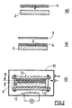
- solder material (4, 41, 42) on the anti-corrosion coating (3, 31, 32), in line with the so-called “bonding surface” And then positioning the support piece (2, 21, 22) on the anti-corrosion coating, so as to form said initial assembly (5, 51, 52).
- the brazing temperature which is typically equal to the melting temperature of the brazing material, is such that the material melts and produces an intimate bond with the element with which it is in contact (metal support part and / or coating anti corrosion).
- the brazing temperature is preferably below about 750 ° C, and more preferably between 600 ° C and 720 ° C. These temperatures make it possible to shorten the duration of the soldering operation.
- the soldering operation normally comprises bringing said determined parts together so as to obtain a spacing D which is preferably chosen from in order to avoid the formation of gas bubbles or bonding defects between the bonding surfaces during the soldering operation.
- the spacing D is typically less than 0.1 mm.
- the method advantageously comprises the application of a plating pressure on said initial assembly (5, 51, 52) during all or part of the soldering operation. More specifically, it is advantageous to apply a plating mechanical pressure to said assembly before and / or during said heating. This plating pressure is exerted so that the support piece and the anti-corrosion coating are clamped against each other and so as to compress the brazing material, which in particular makes it possible to obtain the desired value. for the spacing D between the support piece and the coating.
- the plating pressure may be applied by a mechanical clamping system (12), such as a spring and clamping tie rod system or a pneumatic system (such as an airbag).
- the low temperature brazing operation limits the degradation of the mechanical clamping system (12).
- the plating pressure is typically greater than 0.1 MPa, preferably greater than 0.3 MPa, and more preferably greater than 0.5 MPa.
- Said determined parts are called connecting surfaces.
- the junction between the support member and the coating can be established by a plurality of bonding surfaces.
- the surface (and more precisely the one or more bonding surfaces) of the support pieces (21, 22) and / or coatings (31, 32) is advantageously pre-treated, before the soldering operation, so as, in particular, to remove surface oxides.
- the treatment concerns at least the surface to be coated.
- the method according to the invention may also comprise the deposition of at least one layer capable of improving the adhesion of the brazing material and of limiting the formation of embrittling compounds.
- Deposition may be chemical, electrolytic, or vapor phase (chemical vapor deposition or vapor phase physical deposition).
- Said layer is typically metallic, for example titanium or copper.
- Deposition may be performed on the support member (2, 21, 22), the metal coating (3, 31, 32), or both. The deposit is made before the soldering operation.
- the brazing material is preferably uniformly distributed between the support member and the anti-corrosion coating to provide a uniform bonding layer and to increase the contact area between these two elements.
- the support piece (2, 21, 22) is preferably made of steel.
- the steel used is usually carbon steel or stainless steel.
- the anti-corrosion metal coating (3, 31, 32) is typically titanium, a titanium alloy, a tantalum alloy, a zirconium alloy, a zirconium alloy, a nickel base alloy or a stainless steel alloy. .
- the brazing material (4, 41, 42) may be a fusible alloy (typically a eutectic alloy) or a fusible metal. Said material (4, 41, 42) optionally contains a flux. It is advantageous that the brazing material can diffuse into the element with which it is in contact, which makes it possible to ensure a very strong connection between said elements.
- the brazing material is typically in the form of a powder, a strip or a lattice. In his tests, the Applicant has found that the mesh has the advantage of effectively compensating for any variations in the spacing D between the bonding surfaces.
- the brazing material (4, 41, 42) is typically a material containing silver, copper, zinc, cadmium or tin, or a mixture thereof. elements, whose brazing temperature is less than 750 ° C, and preferably between 600 ° C and 720 ° C.
- the support member (2, 21, 22) and the anti-corrosion coating (3, 31, 32) are typically in the form of a plate or sheet. These elements can be cut beforehand, in particular to form openings and access ways.
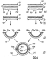
- the support pieces or raw assembly parts (21, 22) may further comprise integrated assembly means, such as protuberances (211, 212, 221, 222).
- the coated shaped parts (111, 112) are typically curved, semi-cylindrical or other shapes.
- the assembly operation of the coated assembly parts (111, 112) to produce a chemical device element (100) comprises the formation of seals (60, 60a, 60b, 70, 70a, 70b) between said parts, typically by welding operations according to any known means.
- the joints between the support pieces (21, 22) are normally made separately from the joints between the facing pieces (31, 32).
- the Applicant has developed a particularly advantageous variant of the method according to the invention wherein the ends (61, 61a, 61b, 62, 62a, 62b) metal parts (21, 22) are previously hollowed out , typically by machining, before the fixing of the coating, as shown in Figure 5.
- This variant greatly facilitates the formation of joints between the assembly parts. In particular, it makes it possible to overcome, after brazing, the machining of the support piece that would otherwise be necessary to make the joints between support pieces.
- the fixing of the coatings on the support pieces is carried out according to the methods described above.
- the recesses (81, 82) serve to prevent brazing between the support pieces (21, 22) and the coatings (31, 32) at the place where they are formed, called the separation zone (91, 92 ) thereafter.
- the depth P of said recesses (81, 82) may be relatively small, typically between 1 and 5 mm, which avoids reducing the mechanical characteristics of the support part (21, 22).
- the width L of said recesses (81, 82) is fixed so as to allow easy clearance of the junction zone between the support pieces.
- the length L is typically between 10 and 50 mm.
- the recess (81, 82) typically takes the form of a flat range parallel to the plane of the ends (61, 62) of the support pieces (21, 22).
- the chemical device element (100) is typically included in the group consisting of storage enclosures, reservoirs, heat exchangers, reactors, mixers, process devices, and delivery devices.
- brazing material was a silver-based alloy containing copper, zinc and tin. Mechanical pressure was applied continuously during the soldering operation. The brazing temperature was below 700 ° C.
- the junction between the steel plate and the tantalum sheet had very few defects after soldering and a hardness not exceeding 150 Hv. Shaping tests, with a small radius of curvature, showed no break in the junction.
- the plated products which are obtained with the process of the invention have the advantage of a high transverse thermal conductivity due to a close connection between the support part and the anti-corrosion coating on the greater part of the bonding surface, which is not the case of a connection obtained, for example, by knurling which produces only connecting cords.
- Transverse thermal conductivity is particularly advantageous in chemical devices comprising heat transfer means such as a heat exchanger or jacket for cooling or heating.
- the plated products according to the invention also have good formability and therefore make it easy to manufacture elements of chemical devices.
- the manufacturing method eliminates the step of machining the support part during subsequent welding operations to manufacture the elements of chemical devices.
Landscapes
- Chemical & Material Sciences (AREA)
- Engineering & Computer Science (AREA)
- Mechanical Engineering (AREA)
- Materials Engineering (AREA)
- Organic Chemistry (AREA)
- Chemical Kinetics & Catalysis (AREA)
- Metallurgy (AREA)
- Other Surface Treatments For Metallic Materials (AREA)
- Physical Or Chemical Processes And Apparatus (AREA)
- Preventing Corrosion Or Incrustation Of Metals (AREA)
- Coating By Spraying Or Casting (AREA)
- Laminated Bodies (AREA)
- Pressure Welding/Diffusion-Bonding (AREA)
- Connection Of Plates (AREA)
Claims (24)
- Verfahren zum Herstellen eines Elementes (100) einer chemischen Vorrichtung enthaltend mindestens ein erstes und ein zweites beschichtetes Verbindungsstück (111, 112), wobei jedes beschichtete Verbindungsstück ein metallisches Trägerstück (21, 22) und mindestens eine metallische Antikorrosionsbeschichtung (31, 32) aufweist, welches Verfahren dadurch gekennzeichnet ist, dass es die folgenden aufeinander folgenden Schritte umfasst:• Herstellung beschichteter Verbindungsvorprodukte (101, 102) nach einem einen Lötvorgang enthaltenden Verfahren umfassend:- die Herstellung einer Grundanordnung (51, 52) enthaltend ein Trägerstück (21, 22), eine Antikorrosionsbeschichtung (31, 32) und mindestens einen Lötwerkstoff (41, 42) zwischen Trägerstück und Beschichtung;- die Einbringung der Grundanordnung (51, 52) in eine Lötkammer mit kontrollierter Atmosphäre (10);- die Bildung einer kontrollierten Atmosphäre in der Kammer (10);- die Erwärmung der Anordnung (51, 52) auf eine mindestens der Löttemperatur des Lötwerkstoffs (41, 42) entsprechende Temperatur, um die Antikorrosionsbeschichtung (31, 32) auf das Trägerstück (21, 22) aufzulöten;• Formgebung der beschichteten Vorprodukte (101, 102), um die beschichteten Verbindungsstücke (111, 112) zu erhalten;• Zusammenbau der beschichteten Verbindungsstücke (111, 112), um das Element (100) einer chemischen Vorrichtung zu erhalten.
- Herstellungsverfahren nach Anspruch 1, dadurch gekennzeichnet, dass die Löttemperatur niedriger als etwa 750°C ist.
- Herstellungsverfahren nach Anspruch 2, dadurch gekennzeichnet, dass die Löttemperatur 600°C bis 720°C beträgt.
- Herstellungsverfahren nach irgendeinem der Ansprüche 1 bis 3, dadurch gekennzeichnet, dass die kontrollierte Atmosphäre im Wesentlichen aus Schutzgas besteht.
- Herstellungsverfahren nach Anspruch 4, dadurch gekennzeichnet, dass das Schutzgas aus der Gruppe bestehend aus den Edelgasen, Stickstoff und deren Gemischen gewählt ist.
- Herstellungsverfahren nach irgendeinem der Ansprüche 1 bis 5, dadurch gekennzeichnet, dass die kontrollierte Atmosphäre der Kammer (10) unter einem Druck P von etwa 102 bis 105 Pa während des Lötens steht.
- Herstellungsverfahren nach irgendeinem der Ansprüche 1 bis 6, dadurch gekennzeichnet, dass es zusätzlich das Anwenden eines Pressdrucks auf die Grundanordnung (51, 52) während des ganzen oder eines Teils des Lötvorgangs umfasst.
- Herstellungsverfahren nach Anspruch 7, dadurch gekennzeichnet, dass der Pressdruck höher als 0,1 MPa, vorzugsweise höher als 0,3 MPa und besonders bevorzugt höher als 0,5 MPa ist.
- Herstellungsverfahren nach irgendeinem der Ansprüche 1 bis 8, dadurch gekennzeichnet, dass es zusätzlich mindestens eine Vorbehandlung der zu beschichtenden Oberfläche der Trägerstücke (21, 22) umfasst und dass diese Behandlung aus der Gruppe bestehend aus den chemischen, elektrochemischen, physikalisch-chemischen und mechanischen Behandlungen und deren Kombinationen gewählt ist.
- Herstellungsverfahren nach irgendeinem der Ansprüche 1 bis 9, dadurch gekennzeichnet, dass es zusätzlich die Abscheidung mindestens einer Schicht umfasst, welche das Haften des Lötwerkstoffs zu verbessern und die Bildung versprödender Verbindungen zu reduzieren vermag.
- Herstellungsverfahren nach Anspruch 10, dadurch gekennzeichnet, dass die Schicht metallisch ist.
- Herstellungsverfahren nach Anspruch 10 oder 11, dadurch gekennzeichnet, dass die Abscheidung chemisch, elektrolytisch oder aus der Dampfphase erfolgt.
- Herstellungsverfahren nach irgendeinem der Ansprüche 1 bis 12, dadurch gekennzeichnet, dass die Dicke der Beschichtung (31, 32) geringer als 1 mm ist.
- Herstellungsverfahren nach irgendeinem der Ansprüche 1 bis 12, dadurch gekennzeichnet, dass die Dicke der Beschichtung (31, 32) geringer als 0,5 mm ist.
- Herstellungsverfahren nach irgendeinem der Ansprüche 1 bis 14, dadurch gekennzeichnet, dass die Beschichtung (31, 32) aus einem Metall ist, gewählt aus der Gruppe bestehend aus Tantal, den Tantallegierungen, Titan, den Titanlegierungen, Zirkonium, den Zirkoniumlegierungen, den Legierungen auf Basis von Nickel und den rostfreien Stählen.
- Herstellungsverfahren nach irgendeinem der Ansprüche 1 bis 15, dadurch gekennzeichnet, dass der Lötwerkstoff (41, 42) Silber, Kupfer, Zink, Kadmium oder Zinn oder ein Gemisch dieser Elemente enthält.
- Herstellungsverfahren nach irgendeinem der Ansprüche 1 bis 16, dadurch gekennzeichnet, dass der Lötwerkstoff in Form von Pulver, Band oder Draht vorliegt.
- Herstellungsverfahren nach irgendeinem der Ansprüche 1 bis 17, dadurch gekennzeichnet, dass das Trägerstück (21, 22) aus Stahl ist.
- Herstellungsverfahren nach Anspruch 18, dadurch gekennzeichnet, dass der Stahl ein Kohlenstoffstahl oder ein rostfreier Stahl ist.
- Herstellungsverfahren nach irgendeinem der Ansprüche 1 bis 19, dadurch gekennzeichnet, dass das Trägerstück (21, 22) als Platte oder Blech ausgebildet ist.
- Herstellungsverfahren nach irgendeinem der Ansprüche 1 bis 20, dadurch gekennzeichnet, dass die Beschichtung (31, 32) als Platte oder Blech ausgebildet ist.
- Herstellungsverfahren nach irgendeinem der Ansprüche 1 bis 21, dadurch gekennzeichnet, dass es weiterhin umfasst:- die Bildung von Ausnehmungen (81, 82) an den zu verbindenden Enden (61, 62) jedes Trägerstücks (21, 22) vor dem Lötvorgang, um das Löten zwischen jeder Beschichtung (31, 32) und jedem Trägerstück (21, 22) auf gleicher Höhe mit den Ausnehmungen zu vermeiden;- die Freilegung der Enden (71, 72) jeder Beschichtung (31, 32) nach dem Lötvorgang;- die Herstellung einer Verbindung (60) zwischen den Enden (61, 62) der Trägerstücke (21, 22);- die Herstellung einer Verbindung (70) zwischen den Enden (71, 72) der Beschichtungen (31, 32).
- Herstellungsverfahren nach Anspruch 22, dadurch gekennzeichnet, dass die Verbindungen (60) zwischen den Enden (61, 62) der Trägerstücke (21, 22) und die Verbindungen (70) zwischen den Enden (71, 72) der Beschichtungen (32, 32) durch Schweißen hergestellt werden.
- Herstellungsverfahren nach irgendeinem der Ansprüche 1 bis 23, dadurch gekennzeichnet, dass das Element (100) einer chemischen Vorrichtung aus der Gruppe der Vorratsbehälter, Reservoirs, Wärmetauscher, Reaktoren, Mischer, Behandlungsvorrichtungen und Zuführungsvorrichtungen gewählt ist.
Applications Claiming Priority (1)
| Application Number | Priority Date | Filing Date | Title |
|---|---|---|---|
| PCT/FR2002/001490 WO2003097230A1 (fr) | 2002-04-29 | 2002-04-29 | Procede de fabrication d'un element de dispositif chimique comportant une piece support en metal et un revetement metallique anti-corrosion |
Publications (2)
| Publication Number | Publication Date |
|---|---|
| EP1499435A1 EP1499435A1 (de) | 2005-01-26 |
| EP1499435B1 true EP1499435B1 (de) | 2006-03-01 |
Family
ID=29266090
Family Applications (1)
| Application Number | Title | Priority Date | Filing Date |
|---|---|---|---|
| EP02732842A Expired - Lifetime EP1499435B1 (de) | 2002-04-29 | 2002-04-29 | Verfahren zum herstellen eines elementes einer chemischen vorrichtung enthaltend ein metallisches haltewerkstück und metallische antikorrosionbeschichtung |
Country Status (11)
| Country | Link |
|---|---|
| US (1) | US6800150B2 (de) |
| EP (1) | EP1499435B1 (de) |
| JP (1) | JP5051975B2 (de) |
| KR (1) | KR100840953B1 (de) |
| CN (1) | CN1292829C (de) |
| AT (1) | ATE318650T1 (de) |
| AU (1) | AU2002304552A1 (de) |
| CA (1) | CA2484028C (de) |
| DE (1) | DE60209483T2 (de) |
| ES (1) | ES2260435T3 (de) |
| WO (1) | WO2003097230A1 (de) |
Cited By (1)
| Publication number | Priority date | Publication date | Assignee | Title |
|---|---|---|---|---|
| FR2918910A1 (fr) * | 2007-07-16 | 2009-01-23 | Carbone Lorraine Equipements G | Procede de fabrication d'un element de genie chimique |
Families Citing this family (16)
| Publication number | Priority date | Publication date | Assignee | Title |
|---|---|---|---|---|
| FR2883006A1 (fr) * | 2005-03-09 | 2006-09-15 | Carbone Lorraine Equipements G | Plaques en acier revetues de zirconium et elements de dispositifs chimiques realises avec de telles plaques |
| CN1981968B (zh) * | 2005-10-19 | 2011-04-13 | 株式会社田村制作所 | 锡焊装置的气氛形成方法和气氛形成装置 |
| FR2913352B1 (fr) * | 2007-03-05 | 2010-11-12 | Carbone Lorraine Equipements G | Enceinte a paroi de grande epaisseur relative resistant au vide et a la pression |
| US7841509B2 (en) * | 2007-10-23 | 2010-11-30 | Gm Global Technology Operations, Inc. | Method of brazing with two different braze compositions |
| GB2470590B (en) * | 2009-05-29 | 2014-07-23 | Astron Advanced Materials Ltd | Electrodeposition of elemental zirconium |
| KR100923841B1 (ko) | 2009-07-11 | 2009-10-27 | 주식회사 일성 | 관체 내부의 내부식성 부재 접합구조 및 방법 |
| CN101941106B (zh) * | 2010-10-25 | 2012-06-27 | 山东大学 | 超级镍叠层材料与Cr18-Ni8不锈钢的高温钎焊工艺 |
| JP5972534B2 (ja) * | 2011-06-22 | 2016-08-17 | 川崎重工業株式会社 | 異材継手および異材継手を用いた構造物 |
| MX350136B (es) * | 2012-05-25 | 2017-08-28 | Shiloh Ind Inc | Pieza de metal en lámina que tiene muesca para soldadura y método para formarla. |
| MX353799B (es) * | 2012-06-29 | 2018-01-30 | Shiloh Ind Inc | Ensamble y método de plantilla soldada. |
| MX381438B (es) * | 2012-11-30 | 2025-03-04 | Twb Company Llc | Metodo para formar una muesca de soldadura en una pieza de metal en hoja. |
| US9956636B2 (en) | 2013-03-14 | 2018-05-01 | Shiloh Industries, Inc. | Welded blank assembly and method |
| JP5729421B2 (ja) | 2013-06-18 | 2015-06-03 | 住友金属鉱山株式会社 | ライニング構造 |
| FR3028023B1 (fr) * | 2014-10-29 | 2019-05-24 | Fives Cryo | Matrice d'echangeur de chaleur resistant a la corrosion et procede de fabrication d'une telle matrice |
| CN109848658B (zh) * | 2019-03-08 | 2021-08-06 | 西安远航真空钎焊技术有限公司 | 一种大面积钛铜薄板的制作方法 |
| CN110722234B (zh) * | 2019-10-11 | 2020-12-04 | 哈尔滨工业大学 | 一种镍钛基合金低温连接接头及其制备方法 |
Family Cites Families (32)
| Publication number | Priority date | Publication date | Assignee | Title |
|---|---|---|---|---|
| US2604395A (en) | 1945-11-19 | 1952-07-22 | Fansteel Metallurgical Corp | Method of producing metallic bodies |
| US3605254A (en) * | 1968-09-06 | 1971-09-20 | Ugine Kuhlmann | Metallurgical bonding |
| US3890110A (en) | 1972-08-29 | 1975-06-17 | Fansteel Inc | Composite coated steel structure for corrosion resistance |
| US3784403A (en) | 1972-08-29 | 1974-01-08 | Fansteel Inc | Process for cladding steel |
| US4098452A (en) * | 1975-03-31 | 1978-07-04 | General Electric Company | Lead bonding method |
| US3986243A (en) | 1975-09-22 | 1976-10-19 | Fansteel Inc. | Method of repairing chemical process equipment |
| US4117201A (en) | 1976-07-23 | 1978-09-26 | Fansteel Inc. | Corrosion and erosion resistant lined equipment |
| US4073427A (en) | 1976-10-07 | 1978-02-14 | Fansteel Inc. | Lined equipment with triclad wall construction |
| US4030848A (en) | 1976-10-18 | 1977-06-21 | Fansteel Inc. | Lined equipment with dual base metal inserts |
| US4030849A (en) | 1976-10-18 | 1977-06-21 | Fansteel Inc. | Lined equipment and method of fabrication |
| US4140172A (en) | 1976-12-23 | 1979-02-20 | Fansteel Inc. | Liners and tube supports for industrial and chemical process equipment |
| JPS5461046A (en) * | 1977-10-26 | 1979-05-17 | Hitachi Ltd | Butt welded joint of clad steel |
| JPS5478720A (en) * | 1977-12-06 | 1979-06-23 | Nippon Hardboard | Production of magnesium carbonate formed body |
| FR2414975A1 (fr) | 1978-01-18 | 1979-08-17 | Snecma | Procede de liaison par brasage-diffusion de pieces en acier inoxydable ou superalliage |
| US4291104A (en) * | 1978-04-17 | 1981-09-22 | Fansteel Inc. | Brazed corrosion resistant lined equipment |
| CA1227972A (en) * | 1982-05-24 | 1987-10-13 | Francis R. Varrese | Method for joining tantalum to non-refractory materials and an apparatus utilizing such a technique |
| US4818629A (en) | 1985-08-26 | 1989-04-04 | Fansteel Inc. | Joint construction for lined equipment |
| JPS635894A (ja) * | 1986-06-26 | 1988-01-11 | Showa Denko Kk | 接着用材料 |
| JPH0252176A (ja) * | 1988-08-17 | 1990-02-21 | Ishikawajima Harima Heavy Ind Co Ltd | チタンクラッド鋼の溶接方法 |
| JPH0370861A (ja) * | 1989-08-11 | 1991-03-26 | Fukui Katsuo | 瀘過装置 |
| JPH04324030A (ja) * | 1991-04-23 | 1992-11-13 | Hitachi Ltd | ガスタービン燃焼器 |
| US5158621A (en) * | 1991-04-29 | 1992-10-27 | Allied-Signal Inc. | Rapidly solidified aluminum-germanium base brazing alloys and method for brazing |
| FR2690860B1 (fr) | 1992-05-06 | 1994-06-17 | Pechiney Recherche | Brasage sous vide aluminium-argent et produit ainsi obtenu. |
| JPH08501551A (ja) * | 1992-09-22 | 1996-02-20 | イー・アイ・デュポン・ドゥ・ヌムール・アンド・カンパニー | 高度にフッ素化されたアルカンの製造のための耐蝕性装置 |
| JP3379056B2 (ja) * | 1995-02-24 | 2003-02-17 | 春川鉄工株式会社 | 制振厚板の溶接方法 |
| JPH08252643A (ja) * | 1995-03-17 | 1996-10-01 | Ishikawajima Harima Heavy Ind Co Ltd | 耐食容器の管台及び胴部の製造方法 |
| DE19601491A1 (de) * | 1996-01-17 | 1997-07-24 | Merten & Storck Gmbh & Co | Emailliertes Kochgeschirr und Verfahren zu seiner Herstellung |
| US5796189A (en) * | 1996-01-23 | 1998-08-18 | General Electric Co. | Brazing procedure for generator liquid cooled stator bars |
| US5701758A (en) | 1996-01-30 | 1997-12-30 | Haramoto; Cary | Refrigeration system accumulating vessel having a brazed, metal-clad deflector |
| GB9823267D0 (en) * | 1998-10-24 | 1998-12-16 | Hardwick Roy | Method of producing a metal composites which can be processed at high temperatures |
| FI114691B (fi) * | 2000-02-23 | 2004-12-15 | Outokumpu Oy | Menetelmä kuparin ja ruostumattoman teräksen välisen liitoksen muodostamiseksi |
| JP2001269795A (ja) * | 2000-03-29 | 2001-10-02 | Citizen Watch Co Ltd | ロウ材及び金属部材とその接合方法 |
-
2002
- 2002-04-29 EP EP02732842A patent/EP1499435B1/de not_active Expired - Lifetime
- 2002-04-29 CN CNB028292413A patent/CN1292829C/zh not_active Expired - Fee Related
- 2002-04-29 KR KR1020047017390A patent/KR100840953B1/ko not_active Expired - Fee Related
- 2002-04-29 JP JP2004504618A patent/JP5051975B2/ja not_active Expired - Fee Related
- 2002-04-29 WO PCT/FR2002/001490 patent/WO2003097230A1/fr not_active Ceased
- 2002-04-29 CA CA2484028A patent/CA2484028C/fr not_active Expired - Fee Related
- 2002-04-29 AT AT02732842T patent/ATE318650T1/de active
- 2002-04-29 AU AU2002304552A patent/AU2002304552A1/en not_active Abandoned
- 2002-04-29 DE DE60209483T patent/DE60209483T2/de not_active Expired - Lifetime
- 2002-04-29 ES ES02732842T patent/ES2260435T3/es not_active Expired - Lifetime
- 2002-06-20 US US10/175,278 patent/US6800150B2/en not_active Expired - Lifetime
Cited By (2)
| Publication number | Priority date | Publication date | Assignee | Title |
|---|---|---|---|---|
| FR2918910A1 (fr) * | 2007-07-16 | 2009-01-23 | Carbone Lorraine Equipements G | Procede de fabrication d'un element de genie chimique |
| WO2009024684A1 (fr) * | 2007-07-16 | 2009-02-26 | Carbone Lorraine Equipements Genie Chimique | Procédé de fabrication d' un élément de génie chimique |
Also Published As
| Publication number | Publication date |
|---|---|
| AU2002304552A1 (en) | 2003-12-02 |
| US20030201037A1 (en) | 2003-10-30 |
| DE60209483T2 (de) | 2006-10-19 |
| EP1499435A1 (de) | 2005-01-26 |
| ATE318650T1 (de) | 2006-03-15 |
| CA2484028C (fr) | 2010-06-22 |
| US6800150B2 (en) | 2004-10-05 |
| JP2005528977A (ja) | 2005-09-29 |
| KR20050006206A (ko) | 2005-01-15 |
| HK1079143A1 (en) | 2006-03-31 |
| CN1292829C (zh) | 2007-01-03 |
| JP5051975B2 (ja) | 2012-10-17 |
| KR100840953B1 (ko) | 2008-06-24 |
| DE60209483D1 (de) | 2006-04-27 |
| WO2003097230A1 (fr) | 2003-11-27 |
| CA2484028A1 (fr) | 2003-11-27 |
| CN1633333A (zh) | 2005-06-29 |
| ES2260435T3 (es) | 2006-11-01 |
Similar Documents
| Publication | Publication Date | Title |
|---|---|---|
| CA2484028C (fr) | Procede de fabrication d'un element de dispositif chimique comportant une piece support en metal et un revetement metallique anti-corrosion | |
| CA2432650C (fr) | Procede de fabrication d'un produit plaque comportant une piece support en acier et un revetement metallique anti-corrosion | |
| US20140057132A1 (en) | Zirconium-coated steel plates and chemical device elements produced with such plates | |
| EP0304654B1 (de) | Verfahren zum Schweissen eines Einschnittes in einem massiven Werkstück aus Stahl und Verwendung dieses Verfahrens zum Reparieren eines gerissenen Rotors | |
| EP4274704B1 (de) | Verfahren zum verbinden eines ersten teils und eines zweiten teils durch direkthartlöten, einschliesslich stufen zur vorbereitung der oberfläche von mindestens einem der teile | |
| JP5485774B2 (ja) | 金属製の支持部品および防食金属被覆を具備する化学装置の構成要素の製造方法 | |
| FR3095151A1 (fr) | Procede d’assemblage d’une piece en carbone et d’une piece metallique par brasage | |
| EP4440769B1 (de) | Verfahren zur herstellung einer doppelschichtigen wärmetauscherwand | |
| EP4470689B1 (de) | Verfahren zur herstellung eines doppelwandigen wärmetauscherrohres | |
| WO1993013884A1 (fr) | Procede et dispositif pour le formage a chaud de metaux ou alliages metalliques | |
| BE863902A (fr) | Raccord soude de paroi composite et procede de fabrication d'une telle paroi |
Legal Events
| Date | Code | Title | Description |
|---|---|---|---|
| PUAI | Public reference made under article 153(3) epc to a published international application that has entered the european phase |
Free format text: ORIGINAL CODE: 0009012 |
|
| 17P | Request for examination filed |
Effective date: 20041105 |
|
| AK | Designated contracting states |
Kind code of ref document: A1 Designated state(s): AT BE CH CY DE DK ES FI FR GB GR IE IT LI LU MC NL PT SE TR |
|
| AX | Request for extension of the european patent |
Extension state: AL LT LV MK RO SI |
|
| GRAP | Despatch of communication of intention to grant a patent |
Free format text: ORIGINAL CODE: EPIDOSNIGR1 |
|
| GRAS | Grant fee paid |
Free format text: ORIGINAL CODE: EPIDOSNIGR3 |
|
| GRAA | (expected) grant |
Free format text: ORIGINAL CODE: 0009210 |
|
| AK | Designated contracting states |
Kind code of ref document: B1 Designated state(s): AT BE CH CY DE DK ES FI FR GB GR IE IT LI LU MC NL PT SE TR |
|
| PG25 | Lapsed in a contracting state [announced via postgrant information from national office to epo] |
Ref country code: IE Free format text: LAPSE BECAUSE OF FAILURE TO SUBMIT A TRANSLATION OF THE DESCRIPTION OR TO PAY THE FEE WITHIN THE PRESCRIBED TIME-LIMIT Effective date: 20060301 Ref country code: FI Free format text: LAPSE BECAUSE OF FAILURE TO SUBMIT A TRANSLATION OF THE DESCRIPTION OR TO PAY THE FEE WITHIN THE PRESCRIBED TIME-LIMIT Effective date: 20060301 |
|
| REG | Reference to a national code |
Ref country code: GB Ref legal event code: FG4D Free format text: NOT ENGLISH |
|
| REG | Reference to a national code |
Ref country code: CH Ref legal event code: EP |
|
| REG | Reference to a national code |
Ref country code: IE Ref legal event code: FG4D Free format text: LANGUAGE OF EP DOCUMENT: FRENCH |
|
| REF | Corresponds to: |
Ref document number: 60209483 Country of ref document: DE Date of ref document: 20060427 Kind code of ref document: P |
|
| PG25 | Lapsed in a contracting state [announced via postgrant information from national office to epo] |
Ref country code: MC Free format text: LAPSE BECAUSE OF NON-PAYMENT OF DUE FEES Effective date: 20060430 |
|
| GBT | Gb: translation of ep patent filed (gb section 77(6)(a)/1977) |
Effective date: 20060502 |
|
| PG25 | Lapsed in a contracting state [announced via postgrant information from national office to epo] |
Ref country code: SE Free format text: LAPSE BECAUSE OF FAILURE TO SUBMIT A TRANSLATION OF THE DESCRIPTION OR TO PAY THE FEE WITHIN THE PRESCRIBED TIME-LIMIT Effective date: 20060601 Ref country code: DK Free format text: LAPSE BECAUSE OF FAILURE TO SUBMIT A TRANSLATION OF THE DESCRIPTION OR TO PAY THE FEE WITHIN THE PRESCRIBED TIME-LIMIT Effective date: 20060601 |
|
| REG | Reference to a national code |
Ref country code: CH Ref legal event code: NV Representative=s name: WILLIAM BLANC & CIE CONSEILS EN PROPRIETE INDUSTRI |
|
| PG25 | Lapsed in a contracting state [announced via postgrant information from national office to epo] |
Ref country code: PT Free format text: LAPSE BECAUSE OF FAILURE TO SUBMIT A TRANSLATION OF THE DESCRIPTION OR TO PAY THE FEE WITHIN THE PRESCRIBED TIME-LIMIT Effective date: 20060801 |
|
| REG | Reference to a national code |
Ref country code: ES Ref legal event code: FG2A Ref document number: 2260435 Country of ref document: ES Kind code of ref document: T3 |
|
| REG | Reference to a national code |
Ref country code: IE Ref legal event code: FD4D |
|
| PLBE | No opposition filed within time limit |
Free format text: ORIGINAL CODE: 0009261 |
|
| STAA | Information on the status of an ep patent application or granted ep patent |
Free format text: STATUS: NO OPPOSITION FILED WITHIN TIME LIMIT |
|
| 26N | No opposition filed |
Effective date: 20061204 |
|
| PG25 | Lapsed in a contracting state [announced via postgrant information from national office to epo] |
Ref country code: GR Free format text: LAPSE BECAUSE OF FAILURE TO SUBMIT A TRANSLATION OF THE DESCRIPTION OR TO PAY THE FEE WITHIN THE PRESCRIBED TIME-LIMIT Effective date: 20060602 |
|
| PG25 | Lapsed in a contracting state [announced via postgrant information from national office to epo] |
Ref country code: LU Free format text: LAPSE BECAUSE OF NON-PAYMENT OF DUE FEES Effective date: 20060429 Ref country code: TR Free format text: LAPSE BECAUSE OF FAILURE TO SUBMIT A TRANSLATION OF THE DESCRIPTION OR TO PAY THE FEE WITHIN THE PRESCRIBED TIME-LIMIT Effective date: 20060301 |
|
| PG25 | Lapsed in a contracting state [announced via postgrant information from national office to epo] |
Ref country code: CY Free format text: LAPSE BECAUSE OF FAILURE TO SUBMIT A TRANSLATION OF THE DESCRIPTION OR TO PAY THE FEE WITHIN THE PRESCRIBED TIME-LIMIT Effective date: 20060301 |
|
| REG | Reference to a national code |
Ref country code: CH Ref legal event code: PFA Owner name: CARBONE LORRAINE EQUIPEMENTS GENIE CHIMIQUE Free format text: CARBONE LORRAINE EQUIPEMENTS GENIE CHIMIQUE#1, RUE JULES FERRY#54530 PAGNY SUR MOSELLE (FR) -TRANSFER TO- CARBONE LORRAINE EQUIPEMENTS GENIE CHIMIQUE#1, RUE JULES FERRY#54530 PAGNY SUR MOSELLE (FR) |
|
| REG | Reference to a national code |
Ref country code: FR Ref legal event code: CD |
|
| REG | Reference to a national code |
Ref country code: CH Ref legal event code: PCAR Free format text: NOVAGRAAF SWITZERLAND SA;CHEMIN DE L'ECHO 3;1213 ONEX (CH) |
|
| REG | Reference to a national code |
Ref country code: FR Ref legal event code: PLFP Year of fee payment: 15 |
|
| REG | Reference to a national code |
Ref country code: FR Ref legal event code: PLFP Year of fee payment: 16 |
|
| PGFP | Annual fee paid to national office [announced via postgrant information from national office to epo] |
Ref country code: CH Payment date: 20170327 Year of fee payment: 16 Ref country code: NL Payment date: 20170322 Year of fee payment: 16 |
|
| PGFP | Annual fee paid to national office [announced via postgrant information from national office to epo] |
Ref country code: BE Payment date: 20170323 Year of fee payment: 16 |
|
| PGFP | Annual fee paid to national office [announced via postgrant information from national office to epo] |
Ref country code: IT Payment date: 20170322 Year of fee payment: 16 Ref country code: ES Payment date: 20170323 Year of fee payment: 16 |
|
| PGFP | Annual fee paid to national office [announced via postgrant information from national office to epo] |
Ref country code: FR Payment date: 20170427 Year of fee payment: 16 Ref country code: GB Payment date: 20170427 Year of fee payment: 16 Ref country code: DE Payment date: 20170430 Year of fee payment: 16 |
|
| PGFP | Annual fee paid to national office [announced via postgrant information from national office to epo] |
Ref country code: AT Payment date: 20170322 Year of fee payment: 16 |
|
| REG | Reference to a national code |
Ref country code: DE Ref legal event code: R119 Ref document number: 60209483 Country of ref document: DE |
|
| REG | Reference to a national code |
Ref country code: CH Ref legal event code: PL |
|
| REG | Reference to a national code |
Ref country code: NL Ref legal event code: MM Effective date: 20180501 |
|
| REG | Reference to a national code |
Ref country code: AT Ref legal event code: MM01 Ref document number: 318650 Country of ref document: AT Kind code of ref document: T Effective date: 20180429 |
|
| REG | Reference to a national code |
Ref country code: BE Ref legal event code: MM Effective date: 20180430 |
|
| GBPC | Gb: european patent ceased through non-payment of renewal fee |
Effective date: 20180429 |
|
| PG25 | Lapsed in a contracting state [announced via postgrant information from national office to epo] |
Ref country code: AT Free format text: LAPSE BECAUSE OF NON-PAYMENT OF DUE FEES Effective date: 20180429 Ref country code: DE Free format text: LAPSE BECAUSE OF NON-PAYMENT OF DUE FEES Effective date: 20181101 Ref country code: NL Free format text: LAPSE BECAUSE OF NON-PAYMENT OF DUE FEES Effective date: 20180501 |
|
| PG25 | Lapsed in a contracting state [announced via postgrant information from national office to epo] |
Ref country code: LI Free format text: LAPSE BECAUSE OF NON-PAYMENT OF DUE FEES Effective date: 20180430 Ref country code: CH Free format text: LAPSE BECAUSE OF NON-PAYMENT OF DUE FEES Effective date: 20180430 Ref country code: GB Free format text: LAPSE BECAUSE OF NON-PAYMENT OF DUE FEES Effective date: 20180429 Ref country code: BE Free format text: LAPSE BECAUSE OF NON-PAYMENT OF DUE FEES Effective date: 20180430 |
|
| PG25 | Lapsed in a contracting state [announced via postgrant information from national office to epo] |
Ref country code: IT Free format text: LAPSE BECAUSE OF NON-PAYMENT OF DUE FEES Effective date: 20180429 Ref country code: FR Free format text: LAPSE BECAUSE OF NON-PAYMENT OF DUE FEES Effective date: 20180430 |
|
| REG | Reference to a national code |
Ref country code: ES Ref legal event code: FD2A Effective date: 20190912 |
|
| PG25 | Lapsed in a contracting state [announced via postgrant information from national office to epo] |
Ref country code: ES Free format text: LAPSE BECAUSE OF NON-PAYMENT OF DUE FEES Effective date: 20180430 |