EP1499764B1 - Fournisseur de fil - Google Patents
Fournisseur de fil Download PDFInfo
- Publication number
- EP1499764B1 EP1499764B1 EP03727222A EP03727222A EP1499764B1 EP 1499764 B1 EP1499764 B1 EP 1499764B1 EP 03727222 A EP03727222 A EP 03727222A EP 03727222 A EP03727222 A EP 03727222A EP 1499764 B1 EP1499764 B1 EP 1499764B1
- Authority
- EP
- European Patent Office
- Prior art keywords
- thread
- feeder
- yarn
- wheel
- storage area
- Prior art date
- Legal status (The legal status is an assumption and is not a legal conclusion. Google has not performed a legal analysis and makes no representation as to the accuracy of the status listed.)
- Expired - Lifetime
Links
- 238000004804 winding Methods 0.000 claims description 22
- 230000001154 acute effect Effects 0.000 claims description 10
- 230000007423 decrease Effects 0.000 claims description 7
- 238000009940 knitting Methods 0.000 description 10
- 239000000919 ceramic Substances 0.000 description 6
- 238000013461 design Methods 0.000 description 5
- 229910052751 metal Inorganic materials 0.000 description 5
- 239000002184 metal Substances 0.000 description 5
- 230000002093 peripheral effect Effects 0.000 description 5
- 239000000969 carrier Substances 0.000 description 4
- 230000000694 effects Effects 0.000 description 4
- 238000005452 bending Methods 0.000 description 3
- 230000008859 change Effects 0.000 description 3
- 230000015572 biosynthetic process Effects 0.000 description 2
- 239000011248 coating agent Substances 0.000 description 2
- 238000000576 coating method Methods 0.000 description 2
- 230000008878 coupling Effects 0.000 description 2
- 238000010168 coupling process Methods 0.000 description 2
- 238000005859 coupling reaction Methods 0.000 description 2
- 238000009730 filament winding Methods 0.000 description 2
- 230000006870 function Effects 0.000 description 2
- 238000009434 installation Methods 0.000 description 2
- 230000007257 malfunction Effects 0.000 description 2
- 238000012549 training Methods 0.000 description 2
- 241000792859 Enema Species 0.000 description 1
- 230000006978 adaptation Effects 0.000 description 1
- 238000013459 approach Methods 0.000 description 1
- 230000009286 beneficial effect Effects 0.000 description 1
- 230000008901 benefit Effects 0.000 description 1
- 238000005524 ceramic coating Methods 0.000 description 1
- 238000011161 development Methods 0.000 description 1
- 239000007920 enema Substances 0.000 description 1
- 229940095399 enema Drugs 0.000 description 1
- 239000004744 fabric Substances 0.000 description 1
- 239000000835 fiber Substances 0.000 description 1
- 230000003993 interaction Effects 0.000 description 1
- 238000004519 manufacturing process Methods 0.000 description 1
- 239000000463 material Substances 0.000 description 1
- 230000004048 modification Effects 0.000 description 1
- 238000012986 modification Methods 0.000 description 1
- 230000001737 promoting effect Effects 0.000 description 1
- 238000007665 sagging Methods 0.000 description 1
- 238000007493 shaping process Methods 0.000 description 1
- 238000004513 sizing Methods 0.000 description 1
- 239000007787 solid Substances 0.000 description 1
- 238000001228 spectrum Methods 0.000 description 1
- 239000012209 synthetic fiber Substances 0.000 description 1
- 229920002994 synthetic fiber Polymers 0.000 description 1
- UONOETXJSWQNOL-UHFFFAOYSA-N tungsten carbide Chemical compound [W+]#[C-] UONOETXJSWQNOL-UHFFFAOYSA-N 0.000 description 1
Images





Classifications
-
- D—TEXTILES; PAPER
- D04—BRAIDING; LACE-MAKING; KNITTING; TRIMMINGS; NON-WOVEN FABRICS
- D04B—KNITTING
- D04B15/00—Details of, or auxiliary devices incorporated in, weft knitting machines, restricted to machines of this kind
- D04B15/38—Devices for supplying, feeding, or guiding threads to needles
- D04B15/48—Thread-feeding devices
Definitions
- the invention relates to a yarn feeding device for delivery a thread to a thread consumption point, such as for example, to the knitting point of a knitting machine.
- Yarn feeding devices serve to thread the yarn from one Pull thread stock, for example, a yarn package and for example with a predetermined thread speed or with specified thread tension or after others Specifications to deliver to a thread-consuming device.
- Such thread-consuming devices can the Knitting of knitting machines or other technical Be facilities.
- the threads are elastic Threads, inelastic threads of natural fibers or synthetic fibers, Staple yarns, other yarns or monofilaments in Consideration.
- the yarn consumption point has no constant thread consumption, so that the yarn delivery to adapt to the thread consumption. This applies, for example, when switching on and off the thread consumption point, For example, in Ringel or Jacquard machines.
- Fritationsfournisseure are known become, with which the thread a rotationally driven Drum wraps around, but he to one or more Positions lifted off the drum.
- the Thread feed wheel through a drum-shaped rod cage is formed.
- two hook-shaped Bending springs arranged, which are the only one, the drum looping thread turn partially from the rod cage take off.
- FR-PS 964455 is another yarn feeding device known, which is a rotationally driven thread supply drum having. This is wrapped in a thread several times. The individual turns of thread thus formed also entwine two pivotally mounted pins, located next to the thread supply drum depending on the pivot position extend parallel or at an acute angle to this. The Pens can pivot away from the drum, thus preventing the To increase thread reserve when the subsequent knitting point no thread decreases.
- a yarn feeding device which is a rotationally driven cylindrical Thread supply drum and one of these associated thread lifting element having.
- the thread lifting element has a kinked thread support surface, the first section at an acute angle of 15 ° to 20 ° to the drum surface extends and its second section in parallel runs to the drum surface.
- the lower end the thread take-off element is forked, with a machine stop lever engages in the bifurcation gap.
- the yarn feeding device has in the neighborhood the Fadenunterrads at least one yarn contact surface on, over which the yarn delivery spanning Turns can run. For this purpose, e.g. a single one Thread lifting element provided. Alternatively, two Thread contact surfaces on two separate thread lifting elements be provided. Both yarn feeding devices is However, the basic geometric design of the thread contact surface (s) the Fadenabhebeelements and the design the Fadenunterrads together.
- the invention Yarn feeding device can be both as a positive feed as well as Fritationsfournisseur use.
- the Fadenarrirad has a yarn inlet area with a Means, which gives the thread winding a feed.
- the thread inlet area is designed as a very steep cone
- the steplessly passes into the memory area for example can be designed as a slender cone.
- the of the yarn thread taken up by the rotating yarn feeding wheel thus squeeze between the inlet area and the Memory area and thus move the winding in the axial direction, to make room for oneself.
- This is especially important for positive operation, in which the Thread does not run over the thread lifting element.
- To friction operation to perform the Fadenabhebeelement allows a limited frictional engagement between the Thread and the yarn feed wheel, so that the yarn feeder at more or less constant speed of the yarn feed wheel can deliver time-varying amounts of thread.
- the feed of the thread winding on the yarn feed wheel can supported by a conicity of the memory area become.
- an acute angle between the Thread abutment surface of Fadenabhebeelements and of the Fadenabhebeelement remote side of the yarn feed wheel cause a winding feed.
- the feed means provided in the inlet area that, as mentioned above, preferably by the shaping the Fadenarrirads itself is formed, can also by be formed elsewhere, which means the filament winding move in the axial direction.
- This can be, for example be arranged in the yarn feed wheel disc, the protruding outwardly through openings of the yarn feed wheel Spokes has.
- the axis of rotation of the disc against the axis of rotation of the yarn feed wheel is slightly inclined, push the spokes of the disc the winding at one Thread feed wheel side axially forward.
- the Memory area by two acute running into each other Cages are formed, which cause a thread feed.
- the yarn feeder with and without Fadenabhebeelement to be used.
- Will the Fadenabhebeelement not used or even removed, causes the feed means the formation of an orderly winding. This can have ten to twenty turns without it Lay turns on top of each other. In friction mode, however be at least several turns of the thread winding over the Fadenabhebeelement and its thread contact surface guided.
- the required winding feed comes here at least partially by the interaction of Fadenabhebeelements with the yarn feed wheel.
- the axial feed force acts on each individual turn, so that on the yarn feed a relatively large Wraps of ten to twenty turns (e.g., fifteen turns) can be accommodated.
- the yarn feed wheel is formed and the Fadenabhebeelement arranged so that in the training Wickel each older turn is slightly shorter than the adjacent younger turn. This is subject to each one Winding the feed effect.
- the Windungsmatiabdging by changing the Inclined position of Fadenabhebeelements be adapted. This can also be between the turns regulate the adjusting distances.
- the yarn contact surface is straight, i. formed bend and kink-free.
- the thread can be Do not change the position of the thread lifting elements. This results in constant conveying conditions.
- the or the thread lifting elements preferably arranged so that of each thread turn of the thread winding less than 240 ° in contact with the thread feed wheel (contact angle), i.e. it is a more than 120 ° section each turn lifted from the yarn feed wheel.
- the whole Wrap is less than 2/3 the length of one completely adjacent (cylindrical) winding on the Thread delivery wheel on.
- the contact angle is preferable greater than 180 °.
- threads can be processed if the distance between the two contact surfaces from each other about 10 mm to 30 mm, preferably 12 mm to 18 mm.
- the thread lifting elements can made of ceramic (wear resistance) or by wire pins or wire hanger (simple production) be formed.
- the thread lifting element by a bent sheet metal part be formed. Is the thread lifting element off Formed metal (wire or sheet metal), it is advantageous a wear-reducing coating, such as to be made of ceramic.
- the yarn feeding device has except the yarn feed wheel preferably no other thread conveyors, such as on the yarn feed belt fitting bands or like that, up.
- the yarn delivery wheel thus has a free outer circumference. This allows a controlled Slippage between thread feed wheel and thread.
- the yarn feed wheel has an inlet section, the e.g. can be conical.
- Conical in this Meaning means that the diameter of the Fadenunterrads in the area of the inlet section depending on the Axial direction changes.
- the cone can take the form of a steep circular cone or other curved shapes exhibit.
- the conical shape allows the generation a thread feed on the yarn feed wheel through the running thread.
- the inlet section is preferably as a closed surface area or as a rod cage educated.
- the yarn feed wheel in an advantageous Embodiment with a conical thread outlet edge be provided.
- This in turn can be frustoconical or otherwise conical.
- the thread run edge allows a Fadenschrägabzug, in particular advantageous for deposits causing yarns is that contain the equipment and sizing or louse heavily.
- a memory area is provided which is preferably is not cylindrical and whose diameter is smaller than the diameter of the inlet section and the thread outlet edge.
- the memory area can be a have polygonal outline, so that the thread turns only of strip-shaped areas of the yarn feed wheel are included.
- the yarn feed wheel can as a rod cage or as an integral part, for example designed as a sheet deep-drawn or as a ceramic part be.
- the polygonal areawise installation of the thread turns allows both in a particularly good way Positive delivery without slippage as well as the slippery Promotion of the thread.
- the outer diameter may be too Slightly remove the thread run out.
- the input yarn guide device of the yarn feeding device is preferably arranged above the storage area, so that the thread is forced over the inlet area of the yarn feed wheel to the storage area to run.
- the input thread guide is included preferably rigidly mounted, what defined thread inlet conditions creates.
- the Output yarn guide also rigidly mounted and preferably located below the storage area. It is preferably axially and radially clear offset against the yarn feed wheel, so they as well stands below the thread outlet edge. This gives the running thread the possibility over the edge of the flow too strip to keep it clean.
- the rigid, if necessary manually adjustable, storage of Ninfadenleit creates defined thread running conditions.
- Both Fadenleit drives are preferably in a plane arranged with the axis of rotation of the yarn feed wheel. This creates symmetrical operating conditions, the yarn feed wheel can be driven clockwise or counterclockwise be.
- the thread lifting element can on the yarn feeding device be permanently mounted. Preferably, however, it is manual adjustable. It can be provided an adjusting device be, with the inclination of the thread lifting element against the longitudinal axis or axis of rotation of the yarn feed wheel adjustable is. This fine adjustments can be made, around the yarn feeding device to different yarn properties or to adapt applications.
- the thread-lifting element on a Circular path to be stored adjustable to the yarn feed wheel is arranged concentrically. This adjustment provides improved manageability, without to influence the thread conveying properties significantly. Especially in tight spaces, for example if very many similar yarn feeding devices on mounted on a machine ring of a circular knitting machine It may be helpful to have a carrier with the lifting element to pivot laterally next to the yarn feeder, to hang up the thread manually. Is he in a hurry, The carrier may remain in this position or vice versa For example, be pivoted 90 °, so that the lifting element under the main body or carrier of the yarn feeder stands and therefore no longer takes up space. For the function of the yarn feeding device is the Position, however, largely irrelevant. This increases not only the ease of use but also the safety against wrong settings.
- the lift-off element projects beyond the storage area both at the inlet section and at the Run edge of the yarn feed wheel. This will ensure that the straight thread abutment surfaces on the extend the entire storage area of the yarn feed wheel.
- the thread lifting element is with the yarn feeding device preferably releasably connected. This allows the yarn feeding device if necessary operated as a pure positive friend become.
- the thread lifting element can be used as or attachment are offered.
- the yarn feeder As a drive for the yarn feed wheel, a pulley serve. It is also possible, the yarn feeder with an individual electric drive motor too provided which drives the yarn feed wheel.
- the drive motor can, for example, according to the thread or be operated thread tension controlled.
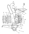
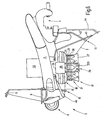
- Figure 1 illustrates a yarn feeding device 1, the serves to a apparent from Figure 2 thread 2 a not further illustrated knitting a Knitting machine or to another thread consumption point to deliver.
- the yarn feeding device 1 has an example made of plastic elongated body 3 on, which at one end with a clamp 4 for attachment the yarn feeding device 1 on an annular support (Machine ring) of a knitting machine is set up.
- an inlet eyelet 7, e.g. made of ceramic, a knot catcher 8, a Yarn brake 9 and one on a rigid support 11 immovable held infeed eyelet 12 include an input Fadenleit worn 13 forms.
- a shaft rotatably mounted which at its upper end one or more Pulleys 14, 15 carries, which have an axial slidable coupling ring 16 optionally rotatably with the shaft can be coupled.
- the shaft is rotatably connected to a yarn feed wheel 17, thus by the pulleys 14, 15 rotating is drivable.
- the yarn feed wheel 17 has an inlet section 18, which is characterized that its diameter with respect to the axial direction A of the yarn feed wheel 17 is reduced from top to bottom.
- the inlet section 18 consists of a first conical section with low opening angle, the arcuate into a second conical section 18b merges with a very large opening angle.
- the conical Section forms a guide surface 18a as a feed means for the winding 26.
- the shaft is essentially vertical oriented. In slip-free operation (positive operation) can not untied thread sagging down like rotate a crank - without being wound backwards become.
- the yarn feed wheel 17 as one piece formed sheet metal deep-drawn part.
- the Memory area 21 is here by a cylindrical Section 22 formed by the ribs 23 protrude.
- the Ribs each have a rounded back on which the thread 2 in individual turns 24, 25, as a winding 26th is applied. Between the individual ribs 23 are the turns 24, 25 of the thread 2 free. Nevertheless, the yarn feed wheel 17 in total free of openings. Also the memory area 21 is closed.
- the storage area 21 can taper slightly towards the bottom.
- the yarn feed wheel 17 runs free, i. it only stands with the thread 2 in contact. There are no more, that Thread feed wheel 17 touching or the thread 2 promotional Elements available.
- the yarn feed wheel 17 is adjacent a thread lifting element 28 arranged according to the figure 1, 2 and 3 by a U-shaped bracket 29 is formed.
- the bracket 29 has two to each other parallel legs 31, 32 on ( Figure 1), the on their lower free end via a web 33 with each other are connected.
- the legs 31, 32 are in their, the Memory area 21 adjacent sections straight and extend at an acute angle or in parallel to the axial direction A, from the axis of rotation of Fadentruckrads 17 is specified.
- the legs 31, 32 thus define yarn contact surfaces 34, 35 (FIG. 2), over which each turn 24, 25, 26 of the thread 2 leads.
- the Yarn pads 34, 35 are curved (e.g., cylindrical arched) and in leg longitudinal direction R each straight over the entire height of the storage area 21.
- the lower ends of the legs 31, 32 are radially something issued to the outside, so that the web 33 of the yarn feed wheel 17 away is angled. The bending point is below the memory area. It prevents you Dropping loose on the thread drum Thread windings.
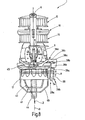
- the Legs 31, 32 preferably above the inlet section 18 bent outwards or angled (Fig. 3). This avoids that incoming thread turns get too far up. This also prevents that thread turns slip over the upper edge of the drum and be wound up by the drum axis.
- the upper, paragraph formed by the bend or bend Pins 31, 32 thus increases the reliability.
- the bracket 29 can in particular on its contact surfaces 34, 35 be provided with a ceramic coating.
- the leg longitudinal direction R is in the axial direction of the yarn feed wheel 17 coincides or closes with this an acute angle. This decreases the length of all Windings 24, 25, 26 from the inlet side to the outlet side from turn to turn off. It happens, as figure 14 illustrates that between the yarn contact surface 34 and one with respect to the yarn feed wheel 17 opposite generatrix M of the storage area 21 an acute angle ⁇ is formed.
- a closed area be.
- the two upper ends of the legs 31, 32 are on a support 36 ( Figures 1 and 3), e.g. to the in the axial direction Ax extending axis of rotation D of the Fadenunterrads 17 pivotally mounted on the main body 3 of the Yarn feeding device 1 is stored.
- the rotation axis D is arranged vertically.
- a spring hinge 37 At its outer end, the Carrier 36, a spring hinge 37, which connects him with the Legs 31, 32 connects.
- the spring hinge 37 stops the legs 31, 32 of the bracket 29 in a relaxed state at an acute angle to the axis of rotation D.
- FIG. 3 illustrates, is in the immediate vicinity of the spring hinge 37, an adjusting screw 38 is provided, the is supported on the carrier 36 and opens up the possibility the pivotal position of the bracket 29 with respect to the carrier 36 to adjust.
- She sits in a threaded hole a base portion 39, via the spring hinge 37 is connected to the carrier 36 and also the upper Ends leg 31, 32 receives.
- she can be in a threaded bore of the carrier 36 and sit at support the base portion 39 (Fig. 1).
- the adjustability the angle of inclination of the bracket 29 allows a Adaptation of the thread feed to different yarn qualities.
- the carrier 36 is designed to hold the bracket 29 and thus the legs 31, 32 at a distance of about 10 mm to 15 mm from the outer periphery of the storage area 21 of the yarn feed wheel 17 stops.
- Figure 12 illustrates this.
- the pin spacing A i. the distance of the thread contact surfaces 34, 35 from each other ( Figure 12) is preferably about 15 mm to 20 mm. This applies to a diameter of the yarn feed wheel of about 45 mm and leads to the desired wrap angle greater than 180 ° but less than 240 °.
- the radius of curvature is r of the thread abutment surfaces 34, 35 smaller than the distance A.
- the thread guide 41, the inlet eye 12 and the axis of rotation D lie in a common plane. Thereby the yarn feeding device 1 has no preferential direction of rotation -
- the yarn feed 17 can be both right and be operated counterclockwise.
- the yarn feeding device 1 described so far works as follows:
- the yarn feed wheel 17 is a via the pulley 14 running, not further illustrated Belt driven by rotation.
- the thread 2 wraps around the yarn feed wheel 17 as illustrated in Figure 2.
- the windings 24, 25, 26 run over the Thread lift-off element 28.
- the speed of the thread feed wheel 17 is dimensioned so that the peripheral speed of the yarn feed wheel is slightly larger than the desired maximum thread speed.
- the windings 24, 25, 26 wrap around the yarn feed wheel 17 each on a large part of its scope, however, are by the Thread lifting element 28 lifted from the yarn feed wheel. This reduces the frictional engagement between the thread 2 and the yarn feed wheel 17, but the friction is so great is that the thread 2 normally with only a small Slip is delivered.
- the thread has a peripheral speed, the e.g. 10% less than the peripheral speed the yarn feed wheel 17.
- the thread lifting element 28 is characterized by that of FIG apparent structure of the adjustment, the off the adjusting screw 38 and the spring hinge 37 is formed is rigidly stored.
- the adjusting screw 38 supports between the yarn feed wheel 17 and the bracket 29 between the carrier 36 and the base portion 39 from, whereas the spring hinge 37 is radially outward. Increased Thread tension can thus no pivoting of the bracket 29 effect on the yarn feed wheel 17.
- the carrier 36 is preferably designed removable.
- the yarn feeding device 1 can then both as a pure Positivfournisseur no slip effect and, as described above, be operated as Fritationsfournisseur, at the knitting point temporarily with reduced thread tension less thread decreases.
- the Carrier 36 can be provided with a hinge or hinge, with the thread-lifting element 28 in a functionless Rest position can be pivoted or folded. It Locking or other locking means may be provided to the thread lifting element respectively in working position and to keep in rest position.
- the yarn feeding device. 1 be used in both ways by the turns 24, 25, 26 optionally placed on the thread lifting element 28 or not be imposed on this.
- Thread lifting element 28 can be made interchangeable, e.g. to provide different brackets 29 for different threads. But it has been shown that all the threads of a wide range of tested threads over one and the same Temple 29 can run when the above geometric conditions are met.
- FIG. 1 A modified embodiment of the yarn feeding device 1 is illustrated in FIG. It's right up to it the yarn feed wheel 17 in all other parts with the above-described yarn feeding device 1 (FIGS. 1 to 3), so that on the basis of the same reference numerals Reference is made to the above description.
- the yarn feed wheel 17 of Figure 4 the Basic structure of a rod cage. It is through several, formed the ribs 23 replacing straight bars 48, the together a cylinder cage or even a very light form conical cage.
- the rods 48 sink into one End plate 49 a, the conical outer surface of the thread run edge 27 forms.
- the rods 48 are also at their upper end in one upper lens 52 taken with its outer surface forms the inlet section 18.
- FIG. 5 Another embodiment of the yarn feeding device 1 is apparent from Figure 5.
- This embodiment is correct largely with the embodiment of Figure 1 to 3 and differs from this only in the formation of the thread outlet edge 27 of the yarn feed wheel 17.
- This is designed as a straight truncated cone, i.e. the radius of the thread outlet edge 27 decreases with the Axial direction of the yarn feed wheel 17 from top to bottom linear to.
- the same applies to the figures 1 to 3 Given structure and functional description based on the same reference numerals.
- FIG. 6 illustrates another embodiment the yarn feeder 1, which is characterized that for driving the yarn feed wheel 17, an electric motor 53 is provided. This sits in the body 3 or protrudes out of this, as shown in Figure 6 can be seen. In addition, it is possible to replace the electric motor 53 in place the pulleys 14, 15 put on top of the body.
- the yarn feed wheel 17 may after each of the above be formed versions described. Here has the lifting of the thread from the yarn feed wheel 17 the Function, with not exactly matching thread delivery and thread take-off, especially if there is a decrease to allow slippage of the yarn feed wheel, without the staffer addressing.
- yarn feeding devices 1 may instead of a thread lifting element 28 with fixed assignment of the two legs 31, 32 to each other and the apparent from Figure 8 design with two thread lifting elements 28a, 28b applied become. Both are each on their own carrier 36a, 36b held over its own base portion 39a, 39b.
- a thread-lifting elements are just trained pins 54, 55, which, like the legs 31, 32 substantially parallel to the axis of rotation D or at an acute angle to these are arranged.
- the pins 54, 55 are parallel aligned with each other, passing through their adjusting screws 38a, 38b, if necessary, also different can be adjusted.
- the two carriers 36a, 36b are independently pivotable so that the pins 54, 55 set at different distances from each other can be.
- FIG. 9 illustrates a modified embodiment of the thread lifting element 28.
- a solid web 56th formed, having an oblong cross-section with rounded Flanks forms. Define the rounded edges the yarn contact surfaces 34, 35.
- the web 56 can, for example made of tungsten carbide, ceramic or another Wear-resistant fabric be formed. He can too bent from sheet metal and with a hard material coating, For example, be provided with ceramic. He is rigid or by means of an adjusting device not further illustrated manually adjustable connected to the carrier 36, an annular projection 57 for attachment to the Basic support 3 has.
- the web 56 may, as Figure 10 illustrates, between his thread abutment surfaces 34, 35 a groove 58th have, which spans the thread 2. It can be an operation as described in connection with FIG. 13 become.
- the distance is between the yarn contact surfaces 34, 35 preferably in Range between 15 mm and 20 mm. This replaces the bridge 56 the bracket 29 and works like this.
- FIG. 7 assumes that both pins 54, 55 arranged at the same distance to the yarn feed wheel 17 are.
- the carriers 36a, 36b are thus the same length. deviant of which the embodiment of Figure 11 looks different long carrier 36a, 36b in front, so the two Pins 54, 55 at different distances to the Rotary axis D and the yarn feed wheel 17 are held. This opens the additional option, the pen 55 ineffective to make by dashed in the 11 in FIG Position 59 is pivoted.
- FIG. 12 illustrates an alternative by dashed lines.
- the legs 31, 32 are by a single thread lifting element 28 'replaces that at a great distance to the yarn feed wheel 17 is arranged. This one is sized that the angle ⁇ is unchanged, the one to the Leg 31 running thread 2 with that of the leg 32nd away running thread 2 includes.
- Figure 13 discloses a further embodiment a yarn feeding device with two pins 54, 55. This are arranged at an angular distance of approximately 180 °.
- the pin 54 is fixed while the pin 55 in Direction of the arrow 61 can be mounted adjustable.
- the pin 54 defines a lift-off zone of e.g. 70 ° while the other lift-off zone is variable.
- the Wrap angle ⁇ is the sum of both partial wrap angles ⁇ 1 and ⁇ 2.
- a thread lifting element 28 On a positive feeder is a thread lifting element 28 provided, the just trained thread contact surfaces 34, 35. These are in their position not adjustable by the thread 2 and allow the Thread as required, a slip in relation to the yarn feed wheel 17. This additional measure thus allows the Positive for the development of applications that him so far because of the required synchronicity between Thread delivery and thread consumption were closed.
Landscapes
- Engineering & Computer Science (AREA)
- Textile Engineering (AREA)
- Knitting Machines (AREA)
- Replacing, Conveying, And Pick-Finding For Filamentary Materials (AREA)
- Length Measuring Devices With Unspecified Measuring Means (AREA)
Claims (11)
- Fournisseur de fil (1) destiné à fournir un fil (2) à un lieu d'utilisation de fil, comprenantune roue de fourniture de fil (17) qui, pour recevoir une bobine de fil (26), présente une partie formant magasin (21) et une zone d'entrée (18) avec un moyen d'avance (18a) destiné à assurer l'avance de la bobine,un moyen d'entraínement en rotation (14, 15, 53) qui est relié à la roue de fourniture de fil, etau moins un élément (28) de séparation de fil qui est disposé à côté de la roue de fourniture de fil (17), est maintenu stationnaire et présente une surface (34) d'application de fil pour des spires (24, 25) de la bobine de fil.
- Fournisseur de fil selon la revendication 1, caractérisé par le fait que le moyen d'avance est constitué d'une surface de guidage (18a) annulaire qui se rétrécit dans la direction axiale (Ax) et se raccorde sans gradin à la partie formant magasin (21).
- Fournisseur de fil selon la revendication 1, caractérisé par le fait que la roue de fourniture de fil (17) est une cage en barreaux, dont les barreaux (48) définissent la partie magasin (21) et la zone d'entrée (18).
- Fournisseur de fil selon la revendication 1, caractérisé par le fait que la roue de fourniture de fil (17) est constituée d'un tambour monobloc avec un profil de nervures (23) dans la partie magasin (21).
- Fournisseur de fil selon la revendication 1, caractérisé par le fait que le diamètre de la partie magasin (21) diminue dans la direction de déplacement du fil.
- Fournisseur de fil selon la revendication 1, caractérisé par le fait qu'en amont de la roue de fourniture de fil (17), il est prévu un dispositif d'entrée de guidage de fil (13), monté de façon stationnaire, pour le fil (2) arrivant à la roue (17) et qu'en aval de la roue de fourniture de fil (17), il est prévu un dispositif de sortie de guidage de fil (41) pour le fil (2) partant de la roue (17).
- Fournisseur de fil selon la revendication 1, caractérisé par le fait que la surface d'application de fil (34) est réalisée sous une forme rectiligne et lisse dans une direction (R) donnée, est maintenue avec une orientation fixe par rapport à la roue de fourniture de fil (17), pendant le fonctionnement du fournisseur de fil (1), et forme un angle aigu (α) avec le côté éloigné de la roue de fourniture de fil (17), l'angle d'enroulement (γ) de chaque spire, formé par le fil de la spire lorsqu'il est appliqué contre la roue de fourniture de fil, étant constant et inférieur à 240°.
- Fournisseur de fil selon la revendication 1, caractérisé par le fait que le dispositif d'entrée de guidage de fil (13), le dispositif de sortie de guidage de fil (41) et la roue de fourniture de fil (17) sont placés dans un même plan et que le dispositif d'entrée de guidage de fil (13) est installé au-dessus de la partie magasin (21), que le dispositif de sortie de guidage de fil (41) est monté de façon rigide et que ledit dispositif (41) est placé en dessous de la partie magasin (21).
- Fournisseur de fil selon la revendication 1, caractérisé par le fait que l'élément de séparation de fil (28, 28a, 28b) est monté avec possibilité de réglage manuel.
- Fournisseur de fil selon la revendication 1, caractérisé par le fait que l'élément de séparation de fil (28, 28a, 28b) dépasse axialement par rapport à la partie magasin (21) de la roue de fourniture de fil (17), dans sa partie d'entrée (18) et au niveau de son bord de sortie de fil (27).
- Fournisseur de fil selon la revendication 1, caractérisé par le fait que l'élément de séparation de fil (28) est monté de façon amovible sur le fournisseur de fil (1).
Applications Claiming Priority (3)
| Application Number | Priority Date | Filing Date | Title |
|---|---|---|---|
| DE10219537A DE10219537B4 (de) | 2002-05-02 | 2002-05-02 | Fadenliefergerät |
| DE10219537 | 2002-05-02 | ||
| PCT/DE2003/001345 WO2003093549A1 (fr) | 2002-05-02 | 2003-04-25 | Fournisseur de fil |
Publications (2)
| Publication Number | Publication Date |
|---|---|
| EP1499764A1 EP1499764A1 (fr) | 2005-01-26 |
| EP1499764B1 true EP1499764B1 (fr) | 2005-12-07 |
Family
ID=29285059
Family Applications (1)
| Application Number | Title | Priority Date | Filing Date |
|---|---|---|---|
| EP03727222A Expired - Lifetime EP1499764B1 (fr) | 2002-05-02 | 2003-04-25 | Fournisseur de fil |
Country Status (10)
| Country | Link |
|---|---|
| US (1) | US7261251B2 (fr) |
| EP (1) | EP1499764B1 (fr) |
| JP (1) | JP2005532481A (fr) |
| KR (1) | KR100638508B1 (fr) |
| CN (1) | CN100359069C (fr) |
| AU (1) | AU2003233766A1 (fr) |
| BR (1) | BR0309352B1 (fr) |
| DE (2) | DE10219537B4 (fr) |
| TW (1) | TWI229157B (fr) |
| WO (1) | WO2003093549A1 (fr) |
Cited By (1)
| Publication number | Priority date | Publication date | Assignee | Title |
|---|---|---|---|---|
| CN103572489A (zh) * | 2012-08-08 | 2014-02-12 | 陈仁惠 | 送纱轮改良构造 |
Families Citing this family (8)
| Publication number | Priority date | Publication date | Assignee | Title |
|---|---|---|---|---|
| DE112007003544B4 (de) * | 2007-06-27 | 2019-06-06 | Memminger-Iro Gmbh | Fadenliefergerät mit überlastsicherer Befestigungsklemme |
| CN101768833B (zh) * | 2008-12-31 | 2012-03-28 | 典洋针织机械股份有限公司 | 机械式不规则送纱装置 |
| CN103510269B (zh) * | 2012-06-26 | 2016-12-21 | 陈仁惠 | 导引式送纱装置 |
| TWI611059B (zh) * | 2014-01-24 | 2018-01-11 | 陳仁惠 | 送紗裝置的分紗桿構造 |
| CN108774799B (zh) * | 2018-07-21 | 2019-11-01 | 绍兴柯桥凯悦针织有限公司 | 一种纺织提拉装置 |
| USD1084074S1 (en) * | 2022-11-16 | 2025-07-15 | Lorri Strong | Feed wheel |
| USD1072010S1 (en) | 2022-11-16 | 2025-04-22 | Brooks Strong | Feed wheel |
| DE102024126937B3 (de) * | 2024-09-19 | 2025-12-11 | Memminger-IRO Gesellschaft mit beschränkter Haftung | Knotenfänger für Textilmaschinen |
Family Cites Families (16)
| Publication number | Priority date | Publication date | Assignee | Title |
|---|---|---|---|---|
| FR964455A (fr) * | 1950-08-17 | |||
| US2189492A (en) * | 1938-10-08 | 1940-02-06 | Worcester Knitting Company | Compensator for feeding elastic thread |
| US2399403A (en) * | 1944-08-05 | 1946-04-30 | Hemphill Co | Yarn feeding device |
| US2641913A (en) * | 1947-04-15 | 1953-06-16 | Poron Ets | Yarn feeding method and apparatus for knitting machines |
| US2539527A (en) * | 1947-11-28 | 1951-01-30 | Hemphill Co | Yarn feeding device |
| SU519513A1 (ru) * | 1974-09-03 | 1976-06-30 | Всесоюзный научно-исследовательский институт трикотажной промышленности | Устройство дл посто нной подачи нити в петлеобразующую систему круглов зальной машины |
| US3922887A (en) * | 1974-09-13 | 1975-12-02 | Singer Co | Positive yarn feeding system for circular knitting machine |
| GB1509309A (en) * | 1976-06-16 | 1978-05-04 | Triplite Ltd | Feeding yarn to textile machinery |
| SU785168A1 (ru) * | 1977-06-07 | 1980-12-07 | Ленинградское Машиностроительное Производственное Объединение Им. Карла Маркса | Устройство дл подачи нити в текстильную машину |
| IT1200374B (it) * | 1982-05-13 | 1989-01-18 | Savio & C Spa | Apparecchio alimentatore di filo per macchine per maglieria a cadute multiple |
| GB2138846B (en) * | 1983-04-27 | 1986-04-23 | Triplite Ltd | Yarn feed device |
| DE3326099C2 (de) * | 1983-07-20 | 1985-05-23 | Memminger Gmbh, 7290 Freudenstadt | Fadenliefervorrichtung für Textilmaschinen |
| JPS60188272A (ja) * | 1984-03-06 | 1985-09-25 | Fukuhara Seiki Seisakusho:Kk | 編機における積極型の糸送り装置 |
| DE3501944A1 (de) * | 1985-01-22 | 1986-07-24 | SIPRA Patententwicklungs- und Beteiligungsgesellschaft mbH, 7470 Albstadt | Fadenliefervorrichtung fuer textilmaschinen |
| DE4301507C2 (de) * | 1993-01-21 | 1995-01-26 | Memminger Iro Gmbh | Fadenbremse |
| US6270032B1 (en) * | 1999-04-03 | 2001-08-07 | Jen Hui Chen | Variable or steady yarn feeding apparatus |
-
2002
- 2002-05-02 DE DE10219537A patent/DE10219537B4/de not_active Expired - Fee Related
-
2003
- 2003-04-25 JP JP2004501681A patent/JP2005532481A/ja active Pending
- 2003-04-25 BR BRPI0309352-2A patent/BR0309352B1/pt not_active IP Right Cessation
- 2003-04-25 CN CNB038098458A patent/CN100359069C/zh not_active Expired - Fee Related
- 2003-04-25 AU AU2003233766A patent/AU2003233766A1/en not_active Abandoned
- 2003-04-25 DE DE50301864T patent/DE50301864D1/de not_active Expired - Lifetime
- 2003-04-25 KR KR1020047017168A patent/KR100638508B1/ko not_active Expired - Fee Related
- 2003-04-25 US US10/513,454 patent/US7261251B2/en not_active Expired - Fee Related
- 2003-04-25 EP EP03727222A patent/EP1499764B1/fr not_active Expired - Lifetime
- 2003-04-25 WO PCT/DE2003/001345 patent/WO2003093549A1/fr not_active Ceased
- 2003-04-30 TW TW092110086A patent/TWI229157B/zh not_active IP Right Cessation
Cited By (1)
| Publication number | Priority date | Publication date | Assignee | Title |
|---|---|---|---|---|
| CN103572489A (zh) * | 2012-08-08 | 2014-02-12 | 陈仁惠 | 送纱轮改良构造 |
Also Published As
| Publication number | Publication date |
|---|---|
| US7261251B2 (en) | 2007-08-28 |
| DE10219537B4 (de) | 2005-12-29 |
| BR0309352A (pt) | 2005-03-08 |
| KR100638508B1 (ko) | 2006-10-26 |
| AU2003233766A1 (en) | 2003-11-17 |
| TWI229157B (en) | 2005-03-11 |
| DE10219537A1 (de) | 2003-11-27 |
| EP1499764A1 (fr) | 2005-01-26 |
| CN100359069C (zh) | 2008-01-02 |
| WO2003093549A1 (fr) | 2003-11-13 |
| JP2005532481A (ja) | 2005-10-27 |
| KR20050006189A (ko) | 2005-01-15 |
| DE50301864D1 (de) | 2006-01-12 |
| US20050126228A1 (en) | 2005-06-16 |
| BR0309352B1 (pt) | 2013-05-21 |
| TW200403368A (en) | 2004-03-01 |
| CN1650058A (zh) | 2005-08-03 |
Similar Documents
| Publication | Publication Date | Title |
|---|---|---|
| EP2122022B1 (fr) | Métiers continus à filer avec dispositif d'amenée de flammes | |
| DE2720519A1 (de) | Verfahren und vorrichtung zum starten des spinnvorgangs beim herstellen eines aus einem mit fasern umwickelten faserbuendels bestehenden garnes | |
| EP1499764B1 (fr) | Fournisseur de fil | |
| DE3326099A1 (de) | Fadenliefervorrichtung fuer textilmaschinen | |
| DE2642183C2 (de) | Fadenliefervorrichtung, insbesondere für Strickmaschinen | |
| CH636651A5 (de) | Vorrichtung an einer spinnmaschine zum einwachsen eines garnes. | |
| EP0779383B1 (fr) | Dispositiv de filature à bout libre | |
| DE1435565A1 (de) | Verfahren und Vorrichtung zum Ziehzwirnen von Garn | |
| DE2050490A1 (de) | Fadenbremsvorrichtung an Doppeldrahtzwirnspindeln | |
| EP3088576A1 (fr) | Procede de fonctionnement d'une broche d'une retordeuse a double fil ou a cable et retordeuse a double fil ou a cable | |
| DD222363A5 (de) | Fadenzufuhreinrichtung fuer strick- oder wirkmaschinen | |
| CH655289A5 (de) | Fadenzuliefergeraet. | |
| DE3006197C2 (de) | Fadenliefervorrichtung, insbesondere für Strickmaschinen | |
| DE19712739A1 (de) | Fadenliefereinrichtung für intermittierenden Fadenverbrauch | |
| DE2559340A1 (de) | Verfahren und vorrichtung fuer die garnzufuehrung | |
| EP0725850A1 (fr) | Dispositif d'amenee du fil pour machines textiles | |
| DE1160340B (de) | Doppeldrahtzwirnspindel mit Fadenspeicherrinne und im Fadenlauf vor dieser liegenden Fadenbremse | |
| DE7535851U (de) | Wickelmaschine | |
| DE2953094A1 (de) | Offen-end-gesponnenes noppengarn sowie verfahren und vorrichtung zu seiner herstellung | |
| EP0217373B1 (fr) | Dispositif d'alimentation de fil pour machines textiles | |
| DE19538135A1 (de) | Fadenvorrichtung für Textilmaschinen | |
| DE102014002882A1 (de) | Arbeitsstelle einer Textilmaschine mit einer Paraffinierungseinrichtung | |
| DE102009025491B4 (de) | Spinn-und Zwirnvorrichtung, insbesondere Spinnrad, mit einem zweifädigen Antrieb | |
| DE321020C (de) | Ringspinnmaschine, bei der der Faden zwischen den Zufuehrwalzen und dem Laeufer Drallerhaelt und eine Bremsvorrichtung die Spannung des oberen Fadenteils vermindert | |
| DE1585063C3 (de) | Fadenzubringer für Rundstrick- und Wirkmaschinen |
Legal Events
| Date | Code | Title | Description |
|---|---|---|---|
| PUAI | Public reference made under article 153(3) epc to a published international application that has entered the european phase |
Free format text: ORIGINAL CODE: 0009012 |
|
| 17P | Request for examination filed |
Effective date: 20041104 |
|
| AK | Designated contracting states |
Kind code of ref document: A1 Designated state(s): AT BE BG CH CY CZ DE DK EE ES FI FR GB GR HU IE IT LI LU MC NL PT RO SE SI SK TR |
|
| AX | Request for extension of the european patent |
Extension state: AL LT LV MK |
|
| GRAP | Despatch of communication of intention to grant a patent |
Free format text: ORIGINAL CODE: EPIDOSNIGR1 |
|
| DAX | Request for extension of the european patent (deleted) | ||
| RBV | Designated contracting states (corrected) |
Designated state(s): DE IT TR |
|
| GRAS | Grant fee paid |
Free format text: ORIGINAL CODE: EPIDOSNIGR3 |
|
| GRAA | (expected) grant |
Free format text: ORIGINAL CODE: 0009210 |
|
| AK | Designated contracting states |
Kind code of ref document: B1 Designated state(s): DE IT TR |
|
| REF | Corresponds to: |
Ref document number: 50301864 Country of ref document: DE Date of ref document: 20060112 Kind code of ref document: P |
|
| PLBE | No opposition filed within time limit |
Free format text: ORIGINAL CODE: 0009261 |
|
| STAA | Information on the status of an ep patent application or granted ep patent |
Free format text: STATUS: NO OPPOSITION FILED WITHIN TIME LIMIT |
|
| 26N | No opposition filed |
Effective date: 20060908 |
|
| PGFP | Annual fee paid to national office [announced via postgrant information from national office to epo] |
Ref country code: DE Payment date: 20180423 Year of fee payment: 16 |
|
| PGFP | Annual fee paid to national office [announced via postgrant information from national office to epo] |
Ref country code: TR Payment date: 20180412 Year of fee payment: 16 Ref country code: IT Payment date: 20180420 Year of fee payment: 16 |
|
| REG | Reference to a national code |
Ref country code: DE Ref legal event code: R119 Ref document number: 50301864 Country of ref document: DE |
|
| PG25 | Lapsed in a contracting state [announced via postgrant information from national office to epo] |
Ref country code: DE Free format text: LAPSE BECAUSE OF NON-PAYMENT OF DUE FEES Effective date: 20191101 |
|
| PG25 | Lapsed in a contracting state [announced via postgrant information from national office to epo] |
Ref country code: IT Free format text: LAPSE BECAUSE OF NON-PAYMENT OF DUE FEES Effective date: 20190425 |
|
| PG25 | Lapsed in a contracting state [announced via postgrant information from national office to epo] |
Ref country code: TR Free format text: LAPSE BECAUSE OF NON-PAYMENT OF DUE FEES Effective date: 20190425 |