EP1499794B1 - Dispositif de separation dans le circuit d'huile d'une automobile - Google Patents
Dispositif de separation dans le circuit d'huile d'une automobile Download PDFInfo
- Publication number
- EP1499794B1 EP1499794B1 EP03718730A EP03718730A EP1499794B1 EP 1499794 B1 EP1499794 B1 EP 1499794B1 EP 03718730 A EP03718730 A EP 03718730A EP 03718730 A EP03718730 A EP 03718730A EP 1499794 B1 EP1499794 B1 EP 1499794B1
- Authority
- EP
- European Patent Office
- Prior art keywords
- oil
- separating device
- air
- tank
- oil tank
- Prior art date
- Legal status (The legal status is an assumption and is not a legal conclusion. Google has not performed a legal analysis and makes no representation as to the accuracy of the status listed.)
- Expired - Lifetime
Links
- 239000004952 Polyamide Substances 0.000 claims description 4
- 229920002647 polyamide Polymers 0.000 claims description 4
- 239000004033 plastic Substances 0.000 claims description 2
- 229920003023 plastic Polymers 0.000 claims description 2
- 239000000463 material Substances 0.000 claims 1
- 239000003921 oil Substances 0.000 description 73
- 238000002485 combustion reaction Methods 0.000 description 3
- 238000005461 lubrication Methods 0.000 description 3
- 238000004519 manufacturing process Methods 0.000 description 3
- 238000001816 cooling Methods 0.000 description 2
- 239000006260 foam Substances 0.000 description 2
- 239000007789 gas Substances 0.000 description 2
- 238000000926 separation method Methods 0.000 description 2
- 230000015572 biosynthetic process Effects 0.000 description 1
- 239000002131 composite material Substances 0.000 description 1
- 238000010276 construction Methods 0.000 description 1
- 230000008878 coupling Effects 0.000 description 1
- 238000010168 coupling process Methods 0.000 description 1
- 238000005859 coupling reaction Methods 0.000 description 1
- 238000007872 degassing Methods 0.000 description 1
- 230000000694 effects Effects 0.000 description 1
- 239000000806 elastomer Substances 0.000 description 1
- 229920001971 elastomer Polymers 0.000 description 1
- 239000000945 filler Substances 0.000 description 1
- 239000003365 glass fiber Substances 0.000 description 1
- 238000001746 injection moulding Methods 0.000 description 1
- 239000007788 liquid Substances 0.000 description 1
- 239000000314 lubricant Substances 0.000 description 1
- 239000010687 lubricating oil Substances 0.000 description 1
- 238000000034 method Methods 0.000 description 1
- 230000002093 peripheral effect Effects 0.000 description 1
- 239000004810 polytetrafluoroethylene Substances 0.000 description 1
- 229920001343 polytetrafluoroethylene Polymers 0.000 description 1
- 238000011144 upstream manufacturing Methods 0.000 description 1
Images
Classifications
-
- F—MECHANICAL ENGINEERING; LIGHTING; HEATING; WEAPONS; BLASTING
- F01—MACHINES OR ENGINES IN GENERAL; ENGINE PLANTS IN GENERAL; STEAM ENGINES
- F01M—LUBRICATING OF MACHINES OR ENGINES IN GENERAL; LUBRICATING INTERNAL COMBUSTION ENGINES; CRANKCASE VENTILATING
- F01M11/00—Component parts, details or accessories, not provided for in, or of interest apart from, groups F01M1/00 - F01M9/00
- F01M11/0004—Oilsumps
-
- F—MECHANICAL ENGINEERING; LIGHTING; HEATING; WEAPONS; BLASTING
- F16—ENGINEERING ELEMENTS AND UNITS; GENERAL MEASURES FOR PRODUCING AND MAINTAINING EFFECTIVE FUNCTIONING OF MACHINES OR INSTALLATIONS; THERMAL INSULATION IN GENERAL
- F16N—LUBRICATING
- F16N39/00—Arrangements for conditioning of lubricants in the lubricating system
- F16N39/002—Arrangements for conditioning of lubricants in the lubricating system by deaeration
-
- F—MECHANICAL ENGINEERING; LIGHTING; HEATING; WEAPONS; BLASTING
- F01—MACHINES OR ENGINES IN GENERAL; ENGINE PLANTS IN GENERAL; STEAM ENGINES
- F01M—LUBRICATING OF MACHINES OR ENGINES IN GENERAL; LUBRICATING INTERNAL COMBUSTION ENGINES; CRANKCASE VENTILATING
- F01M11/00—Component parts, details or accessories, not provided for in, or of interest apart from, groups F01M1/00 - F01M9/00
- F01M11/0004—Oilsumps
- F01M2011/0083—Dry sumps
Definitions
- the invention relates to a separating device in an oil circuit of a motor vehicle, comprising a pressure-generating oil pump and an oil tank, for separating a gas-laden oil flow in a low-air and an air-containing partial flow, with a curved guide rib, by means of which a tangentially introduced on its inner side oil jet deflected / twist is offset.
- oil is used for cooling and / or as a lubricant usually circulating in a cycle.
- oil is pumped from an oil tank / tank by means of an oil pump via leads to the point of action and return lines back into the tank, the pump (s) can be arranged either between the tank and the place of action and / or between the place of action and the tank / can , Since in addition to oil in the circuit normally also air is present, due to the (circulation) movement, a loading of the liquid oil with gaseous air is inevitable, so that the oil foams more or less.
- Air-loaded oil is severely limited in its effect with respect to lubrication and / or heat transportability, which has shown that increased wear and thus a shortened life, for example, an internal combustion engine occur. For this reason, one tries on the one hand by a corresponding oil movement to prevent loading of the oil with air, also oils are used which have a low tendency to foam, on the other hand, it is still necessary to degas frothy air-laden oil again.
- the DE 36 23 238 C2 describes an apparatus for providing substantially air-free lubricating oil, wherein a so-called cyclone separator is used as a central separating element.
- a so-called cyclone separator is used as a central separating element.
- the air-laden oil is introduced via an inlet opening in the cyclone separator, using a portion of the oil pressure energy is separated into a low-or low-emissively outgoing air-poor and a top or central exiting air-containing partial flow.
- Such air separators are known in principle, but they form a separate component, which takes up space and requires a certain manufacturing and assembly costs.
- the air separator is designed as a separate, very complex component with a large number of individual elements and attached with great effort inside the oil tank.
- the invention is therefore based on the object to provide a separating device for separating air from oil in an oil circuit mentioned above with low production and cost as well as space considerations.
- the object is achieved by a separating device with the features of claim 1, wherein according to the underlying idea, the separating device is an integral part of the oil tank.
- the lid of the separator is made of a plastic, such as polyamide.
- the introduced oil jet is formed flat by means of a correspondingly designed introduction device, so that a wide area of the guide rib is acted upon.
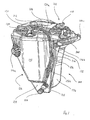
- FIG. 1 shows a consisting of a container 102 and a lid 104 multi-part oil tank 100, the oil tank serves as a container for dry sump lubrication, especially in motorcycles to provide the oil volume.
- both container 102 and cover 104 of the oil tank 100 shown are made of injection-molded glass fiber reinforced polyamide (PA), the tank parts 102, 104 are connected to each other in an oil-tight manner.
- PA injection-molded glass fiber reinforced polyamide
- the stiffening ribs necessary for stiffening the construction are arranged on the inside, so that the tank outer surface is cambered with radii between 250 and 500 mm, the main edges are rounded with radii of about 8 mm.
- the oil tank 100 for use in a motorcycle includes an oil volume of about 3.251 plus 11 corresponding to 25-30% air volume.
- an oil drain 106 is provided, via which oil is conveyed to the place of action, for example, for lubrication and / or cooling of an internal combustion engine during operation by means of a provided between the oil drain 106 and provided in the cover 104 oil feed 108 in the oil circulation pump.
- oil feed 108 in the oil circulation pump.
- upstream of the oil inlet 106 is - not shown - provided an oil cooler.
- a separator 122 is provided for degassing of the foamed oil; The separated gases are removed via an air outlet 110.
- the hose 116 consists in the illustrated embodiment of sections 134a, 134b of an oil-resistant elastomer composite hose and a transparent PTFE tube 136, near which the hose 116 is held with a clamp 132 or clipped on the tank 100.
- the transparent tube 136 markings for the identification of the minimum or maximum oil level are provided, the markings are either on the pipe 136 itself - with the risk of incorrect display due to inaccurate mounting of the hose 116 is - or attached to the tank.
- the hose 116 has a quick coupling for connection to the cover 104, the hose can thus be solved at its upper end and serves as a drain hose, - in this context, it is expedient to lower opening 118 at a very deep, preferably provided at the lowest point of the oil tank 100.
- fastening points 114a, 114b, 114c are provided, wherein the oil tank 100 shown here is attached to the vehicle so that the rear side 124 to the rear wheel and side 126 is turned to the front.
- the side 128 is visible from the side of the motorcycle, so that a review of the oil level and emptying as described advantageously be made possible.
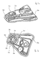
- FIG. 2a An upper shell 204 of an oil tank comprising a separator 222 in plan view is shown in FIG. 2a shown, a view from below shows FIG. 2b ,
- the separator 222 for separating gases from the air-laden oil is integrated in the lid 204 of the oil tank by a corresponding formation of the lid 204 takes place during manufacture in the injection molding process.
- an oil inlet nozzle 208 is provided, which is formed flat nozzle-like in the inlet region 240, so that the introduced oil jet fanned and an improved release of the air bubbles contained is effected.
- the fanned-out oil jet is directed according to its fanning almost tangentially over its entire width on a guide rib 242, which is curved in its further course following the flow of oil inward.
- the flow of oil is deflected in this way and there are centrifugal forces, which cause a separation of the air from the oil.
- Radially within the guide rib 242 is provided by means of an annular rib 244, a dome 246 for forming a space with low air movement, from which the discharge of the separated air without significant turbulence after done up / central.
- the now air-free oil is discharged downwards / peripherally and is available for further use in the oil circuit.
- the oil tank 100 according to the invention is further distinguished by its particularly low weight, the optimized separation of air from the oil circuit contributes to a significant reduction in the wear of the internal combustion engine.
Landscapes
- Engineering & Computer Science (AREA)
- General Engineering & Computer Science (AREA)
- Mechanical Engineering (AREA)
- Lubrication Details And Ventilation Of Internal Combustion Engines (AREA)
Claims (6)
- Installation de séparation pour un circuit d'huile d'un véhicule automobile comprenant une pompe à huile générant de la pression ainsi qu'un réservoir d'huile pour séparer une veine d'huile chargée en gaz en une veine partielle, faiblement chargée en air et une veine partielle chargée en air, ainsi qu'une nervure de guidage, cintrée, à l'aide de laquelle on dévie ou on fait tourner le jet d'huile qui arrive tangentiellement sur son côté intérieur,
caractérisée en ce que
l'installation de séparation (122, 222) fait partie intégrante du réservoir d'huile. - Installation de séparation selon la revendication 1 dans laquelle le réservoir d'huile comporte un réservoir ainsi qu'un couvercle en forme de coupelle,
caractérisée en ce que le couvercle (104, 204) est réalisé de façon à constituer l'installation de séparation (122, 222). - Installation de séparation selon la revendication 2,
caractérisée en ce que
le couvercle est fabriqué en matière plastique, notamment en polyamide. - Installation de séparation selon l'une des revendications 1 à 3,
caractérisée en ce qu'
une installation de guidage (240) de forme appropriée donne une forme plate au jet d'huile entrant. - Installation de séparation selon l'une des revendications 1 à 4,
caractérisée en ce que
la veine partielle faiblement chargée en air est évacuée vers le bas ou de façon périphérique et la veine partielle contenant de l'air est évacuée vers le haut, c'est-à-dire dans la direction centrale. - Installation de séparation selon la revendication 5,
caractérisée en ce que
la veine partielle chargée en air est reconduite par-dessus un dôme (246) en forme de nervure annulaire (244) situé radialement à l'intérieur et concentriquement à la nervure de guidage (242).
Applications Claiming Priority (3)
| Application Number | Priority Date | Filing Date | Title |
|---|---|---|---|
| DE10219279 | 2002-04-30 | ||
| DE2002119279 DE10219279B4 (de) | 2002-04-30 | 2002-04-30 | Trenneinrichtung in einem Ölkreislauf eines Kraftfahrzeugs |
| PCT/EP2003/003508 WO2003093656A1 (fr) | 2002-04-30 | 2003-04-04 | Dispositif de separation dans le circuit d'huile d'une automobile |
Publications (2)
| Publication Number | Publication Date |
|---|---|
| EP1499794A1 EP1499794A1 (fr) | 2005-01-26 |
| EP1499794B1 true EP1499794B1 (fr) | 2008-08-13 |
Family
ID=29264914
Family Applications (1)
| Application Number | Title | Priority Date | Filing Date |
|---|---|---|---|
| EP03718730A Expired - Lifetime EP1499794B1 (fr) | 2002-04-30 | 2003-04-04 | Dispositif de separation dans le circuit d'huile d'une automobile |
Country Status (5)
| Country | Link |
|---|---|
| EP (1) | EP1499794B1 (fr) |
| JP (1) | JP4332495B2 (fr) |
| DE (2) | DE10219279B4 (fr) |
| ES (1) | ES2307921T3 (fr) |
| WO (1) | WO2003093656A1 (fr) |
Families Citing this family (7)
| Publication number | Priority date | Publication date | Assignee | Title |
|---|---|---|---|---|
| GB2421284B (en) | 2004-12-15 | 2008-08-20 | Ford Global Tech Llc | Oil tank for dry sump engines |
| DE102006055760B4 (de) * | 2006-11-25 | 2013-12-19 | Audi Ag | Schmiermitteltank mit einem Gasabscheider |
| US8028672B2 (en) * | 2008-02-27 | 2011-10-04 | GM Global Technology Operations LLC | Dry sump oil tank assembly for a vehicle |
| DE102011104017A1 (de) * | 2011-06-11 | 2012-12-13 | Audi Ag | Behälter für ein Betriebsmedium eines Kraftwagens |
| DE102011104014B4 (de) * | 2011-06-11 | 2020-12-31 | Audi Ag | Behälter für ein Betriebsmedium eines Kraftwagens |
| DE102015116022A1 (de) | 2015-09-22 | 2017-03-23 | Dr. Ing. H.C. F. Porsche Aktiengesellschaft | Verfahren und Vorrichtung zum Abscheiden von Gas aus einem Ölgasgemisch |
| GB201820560D0 (en) | 2018-12-17 | 2019-01-30 | Aston Martin Lagonda Ltd | Assemblies for engines |
Family Cites Families (8)
| Publication number | Priority date | Publication date | Assignee | Title |
|---|---|---|---|---|
| DE693488C (fr) * | 1938-10-14 | 1940-07-10 | Messerschmitt Boelkow Blohm | |
| DE2005594A1 (de) * | 1969-01-23 | 1971-08-19 | Dr Ing h c F Porsche KG, 7000 Stuttgart Zuffenhausen | Vorrichtung zum Entschäumen des Schmiermittels von Brennkraftmaschinen |
| DE1903295A1 (de) * | 1969-01-23 | 1970-08-06 | Porsche Kg | Vorrichtung zum Entschaeumen des Schmiermittels von Brennkraftmaschinen |
| DE2201877A1 (de) * | 1972-01-15 | 1973-07-19 | Steyr Daimler Puch Ag | Entlueftungsvorrichtungfuer das kurbelgehaeuse ventilgesteuerter brennkraftmaschinen |
| DE3623238A1 (de) * | 1986-07-10 | 1988-02-04 | Bayerische Motoren Werke Ag | Vorrichtung zur bereitstellung von im wesentlichen luftfreiem schmieroel |
| DE3711000A1 (de) * | 1987-04-01 | 1988-10-20 | Porsche Ag | Oelbehaelter |
| JPH0396610A (ja) * | 1989-09-08 | 1991-04-22 | Nissan Motor Co Ltd | ドライサンプ用オイルタンク |
| DE10029844B4 (de) * | 2000-06-16 | 2004-04-15 | Dr.Ing.H.C. F. Porsche Ag | Brennkraftmaschine, insbesondere für Motorräder |
-
2002
- 2002-04-30 DE DE2002119279 patent/DE10219279B4/de not_active Expired - Lifetime
-
2003
- 2003-04-04 JP JP2004501783A patent/JP4332495B2/ja not_active Expired - Lifetime
- 2003-04-04 DE DE50310321T patent/DE50310321D1/de not_active Expired - Lifetime
- 2003-04-04 EP EP03718730A patent/EP1499794B1/fr not_active Expired - Lifetime
- 2003-04-04 ES ES03718730T patent/ES2307921T3/es not_active Expired - Lifetime
- 2003-04-04 WO PCT/EP2003/003508 patent/WO2003093656A1/fr not_active Ceased
Also Published As
| Publication number | Publication date |
|---|---|
| DE10219279A1 (de) | 2003-11-20 |
| ES2307921T3 (es) | 2008-12-01 |
| EP1499794A1 (fr) | 2005-01-26 |
| JP4332495B2 (ja) | 2009-09-16 |
| DE50310321D1 (de) | 2008-09-25 |
| DE10219279B4 (de) | 2005-02-24 |
| JP2005524022A (ja) | 2005-08-11 |
| WO2003093656A1 (fr) | 2003-11-13 |
Similar Documents
| Publication | Publication Date | Title |
|---|---|---|
| EP0430056B1 (fr) | Carter d'huile pour un moteur à combustion interne | |
| DE102008060412B4 (de) | Verbrennungsmotor | |
| DE102009010282B4 (de) | Trockensumpf-Ölbehälteranordnung für ein Fahrzeug | |
| EP1080298B2 (fr) | Deshuileur destine a deshuiler les gaz d'aeration du carter d'un moteur a combustion interne | |
| DE10323068B4 (de) | Flüssigkeitstank | |
| EP3271042B1 (fr) | Dispositif filtre | |
| EP2221097B1 (fr) | Dispositif de filtre destiné à l'adsorption d'hydrocarbures | |
| DE2329801A1 (de) | Verfahren und vorrichtung zum abtransport von oel aus oelabscheiderpatronen | |
| DE2854866A1 (de) | Luftansaugvorrichtung fuer eine brennkraftmaschine | |
| DE2650935C3 (de) | Kältemaschine mit gekapseltem Motorverdichter | |
| EP1499794B1 (fr) | Dispositif de separation dans le circuit d'huile d'une automobile | |
| WO2000064300A1 (fr) | Reservoir de liquide de nettoyage pourvu d'un element filtre, destine a un dispositif de nettoyage | |
| DE102010030987B4 (de) | Fluidfilter | |
| EP2714231B1 (fr) | Filtre a huile d'une boite de vitesses pour vehicules automobiles | |
| DE202007003292U1 (de) | Ölabscheider mit mindestens einem Zyklon | |
| DE2606673C2 (de) | Vorrichtung zum Ausscheiden von Gasen aus Flüssigkeiten | |
| WO2002042697A1 (fr) | Collecteur de phase liquide du milieu de travail d'un systeme de climatisation | |
| DE102006017924A1 (de) | Trockensumpfschmierung für eine Brennkraftmaschine sowie Schmieröltank für eine Trockensumpfschmierung | |
| EP3661621B1 (fr) | Élément filtrant | |
| DE10050852A1 (de) | Kühlwasserausgleichsbehälter | |
| DE102012219885B3 (de) | Flüssigkeitsfilter | |
| DE102008060411B4 (de) | Verbrennungsmotor | |
| EP1827955B1 (fr) | Collecteur d'eau projetee pour des vehicules, notamment pour des motos | |
| DE102013113963A1 (de) | Öltank | |
| DE3940299C2 (fr) |
Legal Events
| Date | Code | Title | Description |
|---|---|---|---|
| PUAI | Public reference made under article 153(3) epc to a published international application that has entered the european phase |
Free format text: ORIGINAL CODE: 0009012 |
|
| 17P | Request for examination filed |
Effective date: 20040609 |
|
| AK | Designated contracting states |
Kind code of ref document: A1 Designated state(s): AT BE BG CH CY CZ DE DK EE ES FI FR GB GR HU IE IT LI LU MC NL PT RO SE SI SK TR |
|
| AX | Request for extension of the european patent |
Extension state: AL LT LV MK |
|
| GRAP | Despatch of communication of intention to grant a patent |
Free format text: ORIGINAL CODE: EPIDOSNIGR1 |
|
| GRAS | Grant fee paid |
Free format text: ORIGINAL CODE: EPIDOSNIGR3 |
|
| GRAA | (expected) grant |
Free format text: ORIGINAL CODE: 0009210 |
|
| AK | Designated contracting states |
Kind code of ref document: B1 Designated state(s): DE ES FR GB IT |
|
| REG | Reference to a national code |
Ref country code: GB Ref legal event code: FG4D Free format text: NOT ENGLISH |
|
| REF | Corresponds to: |
Ref document number: 50310321 Country of ref document: DE Date of ref document: 20080925 Kind code of ref document: P |
|
| REG | Reference to a national code |
Ref country code: ES Ref legal event code: FG2A Ref document number: 2307921 Country of ref document: ES Kind code of ref document: T3 |
|
| PLBE | No opposition filed within time limit |
Free format text: ORIGINAL CODE: 0009261 |
|
| STAA | Information on the status of an ep patent application or granted ep patent |
Free format text: STATUS: NO OPPOSITION FILED WITHIN TIME LIMIT |
|
| 26N | No opposition filed |
Effective date: 20090514 |
|
| REG | Reference to a national code |
Ref country code: FR Ref legal event code: PLFP Year of fee payment: 14 |
|
| REG | Reference to a national code |
Ref country code: FR Ref legal event code: PLFP Year of fee payment: 15 |
|
| REG | Reference to a national code |
Ref country code: FR Ref legal event code: PLFP Year of fee payment: 16 |
|
| PGFP | Annual fee paid to national office [announced via postgrant information from national office to epo] |
Ref country code: IT Payment date: 20220429 Year of fee payment: 20 Ref country code: GB Payment date: 20220425 Year of fee payment: 20 Ref country code: FR Payment date: 20220420 Year of fee payment: 20 Ref country code: ES Payment date: 20220518 Year of fee payment: 20 Ref country code: DE Payment date: 20220421 Year of fee payment: 20 |
|
| REG | Reference to a national code |
Ref country code: DE Ref legal event code: R071 Ref document number: 50310321 Country of ref document: DE |
|
| REG | Reference to a national code |
Ref country code: GB Ref legal event code: PE20 Expiry date: 20230403 |
|
| REG | Reference to a national code |
Ref country code: ES Ref legal event code: FD2A Effective date: 20230504 |
|
| PG25 | Lapsed in a contracting state [announced via postgrant information from national office to epo] |
Ref country code: GB Free format text: LAPSE BECAUSE OF EXPIRATION OF PROTECTION Effective date: 20230403 |
|
| P01 | Opt-out of the competence of the unified patent court (upc) registered |
Effective date: 20230502 |
|
| PG25 | Lapsed in a contracting state [announced via postgrant information from national office to epo] |
Ref country code: ES Free format text: LAPSE BECAUSE OF EXPIRATION OF PROTECTION Effective date: 20230405 |