EP1499809B1 - Appareil a ventouse pourvu d'un etrier de serrage a ressort - Google Patents
Appareil a ventouse pourvu d'un etrier de serrage a ressort Download PDFInfo
- Publication number
- EP1499809B1 EP1499809B1 EP03722364A EP03722364A EP1499809B1 EP 1499809 B1 EP1499809 B1 EP 1499809B1 EP 03722364 A EP03722364 A EP 03722364A EP 03722364 A EP03722364 A EP 03722364A EP 1499809 B1 EP1499809 B1 EP 1499809B1
- Authority
- EP
- European Patent Office
- Prior art keywords
- suction
- clamping
- cup device
- extension
- cup
- Prior art date
- Legal status (The legal status is an assumption and is not a legal conclusion. Google has not performed a legal analysis and makes no representation as to the accuracy of the status listed.)
- Expired - Lifetime
Links
Images


Classifications
-
- B—PERFORMING OPERATIONS; TRANSPORTING
- B25—HAND TOOLS; PORTABLE POWER-DRIVEN TOOLS; MANIPULATORS
- B25B—TOOLS OR BENCH DEVICES NOT OTHERWISE PROVIDED FOR, FOR FASTENING, CONNECTING, DISENGAGING, OR HOLDING
- B25B11/00—Work holders not covered by any preceding group in the subclass, e.g. magnetic work holders, vacuum work holders
- B25B11/005—Vacuum work holders
- B25B11/007—Vacuum work holders portable, e.g. handheld
-
- B—PERFORMING OPERATIONS; TRANSPORTING
- B25—HAND TOOLS; PORTABLE POWER-DRIVEN TOOLS; MANIPULATORS
- B25B—TOOLS OR BENCH DEVICES NOT OTHERWISE PROVIDED FOR, FOR FASTENING, CONNECTING, DISENGAGING, OR HOLDING
- B25B5/00—Clamps
- B25B5/006—Supporting devices for clamps
-
- B—PERFORMING OPERATIONS; TRANSPORTING
- B25—HAND TOOLS; PORTABLE POWER-DRIVEN TOOLS; MANIPULATORS
- B25B—TOOLS OR BENCH DEVICES NOT OTHERWISE PROVIDED FOR, FOR FASTENING, CONNECTING, DISENGAGING, OR HOLDING
- B25B5/00—Clamps
- B25B5/06—Arrangements for positively actuating jaws
-
- F—MECHANICAL ENGINEERING; LIGHTING; HEATING; WEAPONS; BLASTING
- F16—ENGINEERING ELEMENTS AND UNITS; GENERAL MEASURES FOR PRODUCING AND MAINTAINING EFFECTIVE FUNCTIONING OF MACHINES OR INSTALLATIONS; THERMAL INSULATION IN GENERAL
- F16B—DEVICES FOR FASTENING OR SECURING CONSTRUCTIONAL ELEMENTS OR MACHINE PARTS TOGETHER, e.g. NAILS, BOLTS, CIRCLIPS, CLAMPS, CLIPS OR WEDGES; JOINTS OR JOINTING
- F16B47/00—Suction cups for attaching purposes; Equivalent means using adhesives
- F16B47/006—Suction cups for attaching purposes; Equivalent means using adhesives the suction cups being activated by the rotation of a cranked lever arm
Definitions
- the invention relates to a suction cup device with a cup-shaped support body and a suction membrane inserted in the cup opening of the supporting body whose center attacks a pull rod, which with its free end a central Passing through the opening of the support body, wherein at the free end to a Swivel axis pivoting tendon is hinged, which tendon around the pivot axis of a release position on a dead center in one Clamping position is pivotable.
- a generic suction cup device is disclosed by DE 2217 638 A.
- a hook is hinged to the drawbar, in the region of the articulation point forms a fork-shaped extension, the function of a tendon Has.
- the pivot axis To hang something on the hook, the pivot axis must be horizontal run.
- the invention is based on the object, the generic suction cup device advantageous to further use.
- Claim 1 initially and essentially provides that the Tension member is associated with a spring tensioning clamp, with two about a hinge axis pivotally interconnected arms, each at one end Have clamping jaws and at the other end operating portions, wherein the hinge axis is transverse to the pivot axis.
- the entire spring tensioning clamp must the pivot axis are pivoted. All this is done vertically aligned axis, so that in the clamping or release operation the Clamping jaw of the clamp always points down.
- the two arms are associated rocker like each other.
- the operating sections are used to disassemble the Tensioning force displaced against the force of a spring.
- This spring also brings the Tension on.
- the tendon may also have a two substantially perpendicular to each other standing surfaces extension of an arcuate Form clamping section of one of the two arms. This extension can be sprayed on the arm made of plastic.
- the extension may have the shape of a truncated pyramid with a fork-shaped opening, which stores the drawbar.
- the axis can be in the center. Further It is advantageous that one of the adjacent jaws and the joint axis defined reference plane parallel to one of the peripheral edge the cup-shaped support body defined attachment level extends.
- the free end of the drawbar can be stored in the fork opening of the extension be that the tendon in opposing pivot directions is displaced into the release position.
- the broad surfaces of the extension can be trapezoidal to the clamping surface of the extension.
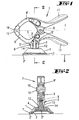
- the section with which the suction cup on a smooth, in particular fastened in the vertical plane consists of the support body 1, which has the shape of a cup.
- the edges of the cup are lost along a truncated cone, so that a parallel to the mounting plane B extending bottom outer surface 14 forms.
- a suction diaphragm 2 made of a soft plastic material.
- the suction membrane 2 also has a cup-shaped design.
- the edge 2 'of the main membrane is 2 lies below the peripheral edge 1' of the support body 1.
- a Pull rod 3 made of a harder plastic. This pull rod 3 protrudes an opening 4, which is located in the center of the bottom outer surface 14.
- the the Opening 4 protruding free portion 3 'of the drawbar 3 protrudes into a fork-shaped Opening a tendon 6 a.
- the two ends 5 'of the axle are in the tendon 6 stored.
- the tendon 6 is from an extension of a Federspannzwingenarms. 9 educated.
- the arm 9 is made of plastic.
- the extension is sprayed on the arm 9.
- the position of the extension lies approximately between the apex of a Clamping portion of the arm 9 and the hinge axis 8.
- the hinge axis 8 is the extension 6 carrying arm 9 with a substantially identical Arm 9 'articulated.
- a tension spring not shown the jaws 10 located at one end of each arm 9,9 ' pressed against each other.
- the two other ends of the two arms 9,9 ' form Operating sections 11 off. Will the two operating sections 11th pressed against each other, so opens the jaw in which the two Clamping jaws 10 from each other.
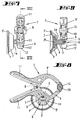
- the tension member 6 formed by the extension has two opposing one another Broad sides 13. These broad sides 13 are smaller from the pivot axis 5 spaced, as a clamping edge 12, the two broad side surfaces 13th connects with each other. In a pivoting position, as shown in Figures 6 to 9 is shown, either one of the two broad sides 13 extends parallel to Bottom outer surface 14. This causes the tie rod to move in the direction of of the edge 1 'of the support body can move to achieve the release position.
- the pivot axis 5 extends in the vertical direction. This has the consequence that the jaws 10 point downwards.
- the through the clamping jaws 10 and the hinge axis 8 defined plane E runs parallel to the fastening plane defined by the marginal edge 1 'of the support body 1 B.
- the pivot axis 5 is spaced from the hinge axis 8. The both axes are skewed so that they are in a projection plane B intersect at right angles.
- the suction cup is due to the above-mentioned negative pressure on the smooth Surface held. Is between the jaws 10 an object, for example, a towel stretched, this is held. Will on the Towel exerted a downward force that is greater than the holding force the two jaws, so the towel from the clamping position be pulled out between the two jaws 10. It is conceivable that the train on the jammed object is not in the direction of Swivel axis 5 takes place, but transversely thereto, in the direction of the hinge axis 8. Bei a train in this direction, which coincide with the horizontal direction can, with sufficient force, the spring tension clamp even to the Swivel axis 5 are pivoted, so that the entire suction cup detached from the smooth surface. As a result, an overload protection is achieved as it were.
Landscapes
- Engineering & Computer Science (AREA)
- Mechanical Engineering (AREA)
- Hooks, Suction Cups, And Attachment By Adhesive Means (AREA)
Claims (7)
- Appareil à ventouse, comprenant un corps d'appui (1), en forme de ventouse, et une membrane d'aspiration (2), s'insérant dans l'ouverture de ventouse du corps d'appui (1), au centre de laquelle agit une tige de traction (3), qui traverse par son extrémité libre (3') une ouverture centrale (4) du corps d'appui (1), de sorte que, sur l'extrémité libre (3'), est articulé un organe de serrage susceptible de pivoter autour d'un axe de pivotement (5), lequel organe de serrage (6) est susceptible de pivoter autour d'un axe de pivotement (5), d'une position de désolidarisation (Figures 6 à 9), en passant par une position de point mort, pour aller à une position de serrage (Figures 1 à 5), caractérisé en qu'à l'organe de serrage (6) est associée une pince de serrage à ressort, comprenant deux bras (9, 9'), reliés ensemble à pivotement autour d'un axe d'articulation et présentant chacun, à une extrémité, des mâchoires de serrage (10) et, à l'autre extrémité, des tronçons d'actionnement (11), l'axe d'articulation (8) s'étendant transversalement par rapport à l'axe de pivotement (5).
- Appareil à ventouse selon la revendication 1 ou en particulier comme suit, caractérisé en ce que les deux bras (9, 9') sont reliés ensemble à la façon d'une bascule et les tronçons d'actionnement (11) peuvent être déplacés l'un vers l'autre à l'encontre de la force d'un ressort pour séparer les mâchoires de serrage (10).
- Appareil à ventouse selon l'une ou plusieurs des revendications précédentes ou en particulier comme suit, caractérisé en ce que l'organe de serrage (6) constitue un prolongement (6), présentant deux surfaces (12, 13) placées sensiblement perpendiculairement l'une par rapport à l'autre ou en forme de trapèze, prolongement d'un tronçon de serrage en forme d'arc d'un des deux bras de serrage (9).
- Appareil à ventouse selon l'une ou plusieurs des revendications précédentes ou en particulier comme suit, caractérisé en ce que le prolongement (6) est disposé entre le sommet de l'arc et l'axe d'articulation (8).
- Appareil à ventouse selon l'une ou plusieurs des revendications 1 précédentes ou en particulier comme suit, caractérisé en ce qu'un plan de référence (E), défini par les mâchoires de serrage (10) placées l'une sur l'autre et l'axe d'articulation (8), s'étend parallèlement à un plan de fixation (B) défini par l'arête de bordure (1') du corps d'appui (1).
- Appareil à ventouse selon l'une ou plusieurs des revendications 1 précédentes ou en particulier comme suit, caractérisé en ce que l'extrémité libre (3') de la tige de traction (3) est montée dans une ouverture de fourche du prolongement (6), de manière que l'organe de serrage soit déplaçable à la position de désolidarisation, en suivant des sens de pivotement mutuellement opposés.
- Appareil à ventouse selon l'une ou plusieurs des revendications 1 précédentes ou en particulier comme suit, caractérisé en que les faces larges (13) du prolongement (6) s'étendent en forme de trapèze par rapport à la surface de serrage (12).
Applications Claiming Priority (3)
| Application Number | Priority Date | Filing Date | Title |
|---|---|---|---|
| DE20206846U | 2002-04-30 | ||
| DE20206846U DE20206846U1 (de) | 2002-04-30 | 2002-04-30 | Saugnapfgerät mit Federspannzwinge |
| PCT/EP2003/003235 WO2003093693A1 (fr) | 2002-04-30 | 2003-03-28 | Appareil a ventouse pourvu d'un etrier de serrage a ressort |
Publications (2)
| Publication Number | Publication Date |
|---|---|
| EP1499809A1 EP1499809A1 (fr) | 2005-01-26 |
| EP1499809B1 true EP1499809B1 (fr) | 2005-10-05 |
Family
ID=28051389
Family Applications (1)
| Application Number | Title | Priority Date | Filing Date |
|---|---|---|---|
| EP03722364A Expired - Lifetime EP1499809B1 (fr) | 2002-04-30 | 2003-03-28 | Appareil a ventouse pourvu d'un etrier de serrage a ressort |
Country Status (7)
| Country | Link |
|---|---|
| US (1) | US6799756B2 (fr) |
| EP (1) | EP1499809B1 (fr) |
| CN (1) | CN1292174C (fr) |
| AU (1) | AU2003229578A1 (fr) |
| CA (1) | CA2427341C (fr) |
| DE (2) | DE20206846U1 (fr) |
| WO (1) | WO2003093693A1 (fr) |
Families Citing this family (33)
| Publication number | Priority date | Publication date | Assignee | Title |
|---|---|---|---|---|
| US20040064996A1 (en) * | 2002-10-07 | 2004-04-08 | Armenti Nicholas P. | Fish holder spring clamp system |
| GB0400937D0 (en) * | 2004-01-16 | 2004-02-18 | Farrell Brothers Res Ltd | A clamp |
| US20060185765A1 (en) * | 2005-02-22 | 2006-08-24 | Bates Charles E Iii | Fuel pump nozzle lever holding device |
| ATE541383T1 (de) | 2005-11-04 | 2012-01-15 | Research In Motion Ltd | Korrektur von fehlern in funkkommunikationen in abhängigkeit von der fehlerfrequenz |
| US8213317B2 (en) | 2005-11-04 | 2012-07-03 | Research In Motion Limited | Procedure for correcting errors in radio communication, responsive to error frequency |
| US7128313B1 (en) * | 2006-02-28 | 2006-10-31 | Pliley Larry E | Support system of a tabletop vise |
| FR2900358B1 (fr) * | 2006-04-27 | 2009-02-06 | Airbus France Sas | Outil de pressage articule |
| US7648130B2 (en) | 2006-06-08 | 2010-01-19 | Research In Motion Limited | Use of magnets to provide resilience |
| ATE494106T1 (de) * | 2006-06-08 | 2011-01-15 | Research In Motion Ltd | Spannkrafterzeugung durch die benutzung von magneten |
| US20080061210A1 (en) * | 2006-09-11 | 2008-03-13 | Carnevali Jeffrey D | Sheet music stand |
| US20080061197A1 (en) * | 2006-09-11 | 2008-03-13 | Carnevali Jeffrey D | Universal detachable presentation bracket |
| AU2007216907B2 (en) * | 2007-09-21 | 2012-11-29 | Pryor, Dennis | Mosquito coil holder |
| US8393062B2 (en) * | 2008-03-31 | 2013-03-12 | United Technologies Corp. | Systems and methods for positioning fairing sheaths of gas turbine engines |
| US8333353B1 (en) * | 2008-06-09 | 2012-12-18 | Brandra, LLC | Compact, portable, temporary mount for portable devices |
| US7950122B2 (en) | 2008-12-01 | 2011-05-31 | Saylor Lewis J | Pool cue clamp |
| US20100314507A1 (en) * | 2009-06-11 | 2010-12-16 | Toni Laitila | Adjustable Bag Retaining Apparatus |
| GB201013953D0 (en) * | 2010-08-20 | 2010-10-06 | Envirotech Ltd | Attachment system |
| CN102882065B (zh) * | 2011-07-13 | 2016-01-20 | 英业达股份有限公司 | 缆线固定座 |
| CN102824089A (zh) * | 2012-08-23 | 2012-12-19 | 成都博达供应链管理有限公司 | 利用吸附力稳固物品的夹紧装置 |
| CA2935592C (fr) | 2014-01-20 | 2023-03-21 | Parker-Hannifin Corporation | Systeme de capteurs sans tuyau pour unite de fluide frigorigene |
| KR200473759Y1 (ko) * | 2014-02-27 | 2014-08-01 | (주)신형아이엔티 | 집게타입 모바일기기용 마운트 |
| CN104290055A (zh) * | 2014-08-22 | 2015-01-21 | 成都飞机工业(集团)有限责任公司 | 可调夹紧装置 |
| TW201615328A (zh) * | 2014-10-21 | 2016-05-01 | Sportsman Corp | 固持夾具 |
| USD795684S1 (en) * | 2016-04-28 | 2017-08-29 | Walter R. Tucker Enterprises, Ltd. | Clamp |
| CN105936016A (zh) * | 2016-06-28 | 2016-09-14 | 无锡市锡山区羊尖镇锦达商业设备厂 | 一种用于变速箱壳体加工的夹具 |
| CN106563963B (zh) * | 2016-10-20 | 2019-04-02 | 成都久欣时代科技有限公司 | 一种铰接可调式导弹叶片夹持装置 |
| CN107717530A (zh) * | 2017-09-15 | 2018-02-23 | 徐州松惠机电有限公司 | 一种机电零件快速压紧装置 |
| CN107651444A (zh) * | 2017-11-10 | 2018-02-02 | 江苏亚威机床股份有限公司 | 一种窄长工件机器人自动折弯抓手装置 |
| CU24772B1 (es) * | 2020-07-15 | 2025-12-08 | Elena Igorevna Kazanceva | Soporte para secador de pelo |
| US11279604B1 (en) * | 2021-10-16 | 2022-03-22 | Dennis Klem | Removably attachable clamp device |
| CN114147603B (zh) * | 2021-12-14 | 2023-01-10 | 广东电网有限责任公司 | 一种线夹固定装置 |
| US11883933B1 (en) | 2022-08-24 | 2024-01-30 | Ifixit | Screw-driven spreading tool with a disengage |
| CN115979607A (zh) * | 2022-12-30 | 2023-04-18 | 湖南中联重科应急装备有限公司 | 滑斗刹车可靠性测试装置 |
Family Cites Families (33)
| Publication number | Priority date | Publication date | Assignee | Title |
|---|---|---|---|---|
| DE475317C (de) * | 1929-04-22 | Kremp & Huettenmeister | Gummisaughalter zum Befestigen von auszustellenden Gegenstaenden an glatten Flaechen | |
| US803668A (en) * | 1904-09-30 | 1905-11-07 | William H Clendenon | Clamp. |
| US2667678A (en) * | 1950-04-28 | 1954-02-02 | John M Hargrave | Hand clamp |
| US2815777A (en) * | 1954-11-23 | 1957-12-10 | Iraids Arvids | Spring actuated miter clamp |
| US3159370A (en) * | 1962-01-31 | 1964-12-01 | Gen Slicing Machine Co Inc | Vacuum bases |
| CH511375A (de) * | 1969-07-03 | 1971-08-15 | Hoeffleur Albert | Klammer |
| US3750991A (en) * | 1971-05-05 | 1973-08-07 | M Ragir | Suction mounting device |
| US3779108A (en) * | 1971-05-19 | 1973-12-18 | J Reiter | Clamp |
| US3770259A (en) * | 1972-10-20 | 1973-11-06 | M Wagreich | Vacuumatic clamp |
| US4580751A (en) * | 1984-07-05 | 1986-04-08 | Panzer Elinor S | Suction cup support particularly for a shower head with handle affixed to a shower hose |
| US4813107A (en) * | 1987-09-04 | 1989-03-21 | Warren Tool Corporation | Spring clamp |
| US4844779A (en) * | 1988-01-25 | 1989-07-04 | Callahan Norman F | Metal treatment clamp and method and apparatus for using the same |
| USD317116S (en) * | 1989-02-16 | 1991-05-28 | Warren Tool Corporation | Spring clamp |
| US4994548A (en) * | 1989-05-09 | 1991-02-19 | Shell Oil Company | Modified bisphenol resins having at least one arylcyclo-butanenealkyl moiety |
| US4944548A (en) * | 1989-08-21 | 1990-07-31 | Payne George E | Side window shade for automobiles |
| GB2240309B (en) * | 1990-01-24 | 1993-09-22 | Devendra Prabhudas Dolasia | A driving mirror |
| USD322390S (en) * | 1990-01-29 | 1991-12-17 | Warren Tool Corporation | Spring clamp |
| DE69120256T2 (de) | 1990-02-09 | 1997-01-30 | Wilfried 51373 Leverkusen Lichtenberg | Spannzwinge mit drehbaren und verschiebbaren backen |
| US5022291A (en) * | 1990-08-06 | 1991-06-11 | Mcbain Corey L | Pliers having a pivotal jaw |
| USD350892S (en) * | 1993-06-10 | 1994-09-27 | Petersen Manufacturing Co. Inc. | Spring clamp |
| USD348743S (en) * | 1993-06-28 | 1994-07-12 | Leen & Associates, Inc. | Halogen clamp lamp |
| US5381989A (en) * | 1994-02-07 | 1995-01-17 | Jackson; Ronald E. | Adjustable spring clamp |
| US5485988A (en) * | 1994-05-31 | 1996-01-23 | Nobilec; Leslaw | Clamping means for ski, or the like |
| US5645254A (en) | 1995-02-02 | 1997-07-08 | Noma, Inc. | Seasonal decoration mounting arrangement |
| DE29506836U1 (de) * | 1995-04-22 | 1996-08-22 | wolfcraft GmbH, 56745 Weibern | Federspannzwinge |
| US5765820A (en) * | 1995-08-17 | 1998-06-16 | Marusiak; Frank | Three-way spring clamp |
| CN1076798C (zh) * | 1996-01-09 | 2001-12-26 | 西马洲际股份有限公司 | 用于可拆卸地卡紧两部分的夹持装置 |
| US5772468A (en) * | 1996-09-27 | 1998-06-30 | Coleman Cable System, Inc. | Clamp assembly for a battery booster cable |
| US5820116A (en) * | 1997-05-02 | 1998-10-13 | Haese; Robert W. | Suction attachable retaining clamp |
| US6175998B1 (en) * | 1998-06-10 | 2001-01-23 | Mark D. Leo | Hand tool for gripping and joining duct sections |
| US6257039B1 (en) * | 1998-08-17 | 2001-07-10 | Childress Luellen | Paper clamp press |
| US6240815B1 (en) * | 2000-05-30 | 2001-06-05 | Chun-Nuan Huang | Workpiece clamping device |
| US6336386B1 (en) * | 2000-07-21 | 2002-01-08 | Yung Jen Lee | Plier device having an adjustable opening |
-
2002
- 2002-04-30 DE DE20206846U patent/DE20206846U1/de not_active Expired - Lifetime
-
2003
- 2003-03-28 CN CN03809557.2A patent/CN1292174C/zh not_active Expired - Lifetime
- 2003-03-28 WO PCT/EP2003/003235 patent/WO2003093693A1/fr not_active Ceased
- 2003-03-28 DE DE50301313T patent/DE50301313D1/de not_active Expired - Lifetime
- 2003-03-28 EP EP03722364A patent/EP1499809B1/fr not_active Expired - Lifetime
- 2003-03-28 AU AU2003229578A patent/AU2003229578A1/en not_active Abandoned
- 2003-04-30 US US10/427,849 patent/US6799756B2/en not_active Expired - Lifetime
- 2003-04-30 CA CA2427341A patent/CA2427341C/fr not_active Expired - Lifetime
Also Published As
| Publication number | Publication date |
|---|---|
| DE20206846U1 (de) | 2003-09-11 |
| WO2003093693A8 (fr) | 2005-02-03 |
| CN1650113A (zh) | 2005-08-03 |
| CA2427341C (fr) | 2011-03-15 |
| CN1292174C (zh) | 2006-12-27 |
| DE50301313D1 (de) | 2005-11-10 |
| US6799756B2 (en) | 2004-10-05 |
| US20040004318A1 (en) | 2004-01-08 |
| EP1499809A1 (fr) | 2005-01-26 |
| CA2427341A1 (fr) | 2003-10-30 |
| WO2003093693A1 (fr) | 2003-11-13 |
| AU2003229578A1 (en) | 2003-11-17 |
Similar Documents
| Publication | Publication Date | Title |
|---|---|---|
| EP1499809A1 (fr) | Appareil a ventouse pourvu d'un etrier de serrage a ressort | |
| EP2646698B1 (fr) | Vis à boucle | |
| EP1884410B1 (fr) | Porte-charge | |
| EP1935297B1 (fr) | Aide à l'enfilage de chaussettes | |
| DE102005048341A1 (de) | Scheibenwischvorrichtung | |
| EP2745739B1 (fr) | Dispositif d'accroche pour meuble mural | |
| DE2608909A1 (de) | Quetschmop | |
| EP2940216A1 (fr) | Protection latérale de lame de chasse-neige | |
| DE102006034306A1 (de) | Möbelscharnier | |
| EP2361808B1 (fr) | Porte-charge arrière | |
| DE202005007464U1 (de) | Zangengreifer | |
| EP2718640B1 (fr) | Agencement d'un module photovoltaïque encadré sur un support | |
| EP2248974B1 (fr) | Charnière avec multiple points d'appui | |
| EP1852564A2 (fr) | Fixation de tuyau, en particulier pour des tuyaux d'extrémité sur des mâts de pompes à béton | |
| DE102021134454B3 (de) | Greifer | |
| EP1392144B1 (fr) | Dispositif pour tendre une chaussette | |
| DE10043569C2 (de) | Haltevorrichtung für Schmuck, insbesondere Ohrschmuck | |
| EP0492513B1 (fr) | Porte-bagages | |
| DE102018222826A1 (de) | Dämpfungsscharnier | |
| AT404929B (de) | Halter für müllsäcke | |
| EP3701835B1 (fr) | Dispositif de raccordement d'un élément frontal ayant une partie latérale mobile d'un meuble | |
| DE202004018171U1 (de) | Transportbügel | |
| DE2517829A1 (de) | Vorrichtung zum abbremsen eines skis nach dem loesen vom skischuh (skibremse) | |
| WO1994023110A1 (fr) | Agrafe de retenue pour textiles | |
| EP0352270A1 (fr) | Dispositif de fixation amovible du wishbone au mat d'une planche a voile |
Legal Events
| Date | Code | Title | Description |
|---|---|---|---|
| PUAI | Public reference made under article 153(3) epc to a published international application that has entered the european phase |
Free format text: ORIGINAL CODE: 0009012 |
|
| 17P | Request for examination filed |
Effective date: 20040909 |
|
| AK | Designated contracting states |
Kind code of ref document: A1 Designated state(s): AT BE BG CH CY CZ DE DK EE ES FI FR GB GR HU IE IT LI LU MC NL PT RO SE SI SK TR |
|
| AX | Request for extension of the european patent |
Extension state: AL LT LV MK |
|
| RAP1 | Party data changed (applicant data changed or rights of an application transferred) |
Owner name: WOLFCRAFT GMBH |
|
| GRAP | Despatch of communication of intention to grant a patent |
Free format text: ORIGINAL CODE: EPIDOSNIGR1 |
|
| RBV | Designated contracting states (corrected) |
Designated state(s): DE FR GB |
|
| GRAS | Grant fee paid |
Free format text: ORIGINAL CODE: EPIDOSNIGR3 |
|
| GRAA | (expected) grant |
Free format text: ORIGINAL CODE: 0009210 |
|
| AK | Designated contracting states |
Kind code of ref document: B1 Designated state(s): DE FR GB |
|
| REG | Reference to a national code |
Ref country code: GB Ref legal event code: FG4D Free format text: NOT ENGLISH |
|
| GBT | Gb: translation of ep patent filed (gb section 77(6)(a)/1977) |
Effective date: 20051005 |
|
| REF | Corresponds to: |
Ref document number: 50301313 Country of ref document: DE Date of ref document: 20051110 Kind code of ref document: P |
|
| ET | Fr: translation filed | ||
| PLBE | No opposition filed within time limit |
Free format text: ORIGINAL CODE: 0009261 |
|
| STAA | Information on the status of an ep patent application or granted ep patent |
Free format text: STATUS: NO OPPOSITION FILED WITHIN TIME LIMIT |
|
| 26N | No opposition filed |
Effective date: 20060706 |
|
| PGFP | Annual fee paid to national office [announced via postgrant information from national office to epo] |
Ref country code: GB Payment date: 20090316 Year of fee payment: 7 |
|
| GBPC | Gb: european patent ceased through non-payment of renewal fee |
Effective date: 20100328 |
|
| PG25 | Lapsed in a contracting state [announced via postgrant information from national office to epo] |
Ref country code: GB Free format text: LAPSE BECAUSE OF NON-PAYMENT OF DUE FEES Effective date: 20100328 |
|
| REG | Reference to a national code |
Ref country code: FR Ref legal event code: PLFP Year of fee payment: 14 |
|
| REG | Reference to a national code |
Ref country code: FR Ref legal event code: PLFP Year of fee payment: 15 |
|
| REG | Reference to a national code |
Ref country code: FR Ref legal event code: PLFP Year of fee payment: 16 |
|
| PGFP | Annual fee paid to national office [announced via postgrant information from national office to epo] |
Ref country code: DE Payment date: 20220318 Year of fee payment: 20 |
|
| PGFP | Annual fee paid to national office [announced via postgrant information from national office to epo] |
Ref country code: FR Payment date: 20220316 Year of fee payment: 20 |
|
| REG | Reference to a national code |
Ref country code: DE Ref legal event code: R071 Ref document number: 50301313 Country of ref document: DE |