EP1500603A1 - Recipient verseur - Google Patents
Recipient verseur Download PDFInfo
- Publication number
- EP1500603A1 EP1500603A1 EP03725703A EP03725703A EP1500603A1 EP 1500603 A1 EP1500603 A1 EP 1500603A1 EP 03725703 A EP03725703 A EP 03725703A EP 03725703 A EP03725703 A EP 03725703A EP 1500603 A1 EP1500603 A1 EP 1500603A1
- Authority
- EP
- European Patent Office
- Prior art keywords
- container
- discharge
- cylinder
- check valve
- contents
- Prior art date
- Legal status (The legal status is an assumption and is not a legal conclusion. Google has not performed a legal analysis and makes no representation as to the accuracy of the status listed.)
- Granted
Links
Images








Classifications
-
- A—HUMAN NECESSITIES
- A46—BRUSHWARE
- A46B—BRUSHES
- A46B11/00—Brushes with reservoir or other means for applying substances, e.g. paints, pastes, water
- A46B11/0072—Details
- A46B11/0079—Arrangements for preventing undesired leakage or dispensing
- A46B11/0086—Means for closing or sealing, e.g. toothpaste outlet when brush not in use thereby preventing leakage or drying out
-
- A—HUMAN NECESSITIES
- A45—HAND OR TRAVELLING ARTICLES
- A45D—HAIRDRESSING OR SHAVING EQUIPMENT; EQUIPMENT FOR COSMETICS OR COSMETIC TREATMENTS, e.g. FOR MANICURING OR PEDICURING
- A45D24/00—Hair combs for care of the hair; Accessories therefor
- A45D24/22—Combs with dispensing devices for liquids, pastes or powders
-
- A—HUMAN NECESSITIES
- A45—HAND OR TRAVELLING ARTICLES
- A45D—HAIRDRESSING OR SHAVING EQUIPMENT; EQUIPMENT FOR COSMETICS OR COSMETIC TREATMENTS, e.g. FOR MANICURING OR PEDICURING
- A45D24/00—Hair combs for care of the hair; Accessories therefor
- A45D24/22—Combs with dispensing devices for liquids, pastes or powders
- A45D24/26—Combs with dispensing devices for liquids, pastes or powders with flexible walls of the liquid, paste, or powder storing device
-
- A—HUMAN NECESSITIES
- A46—BRUSHWARE
- A46B—BRUSHES
- A46B11/00—Brushes with reservoir or other means for applying substances, e.g. paints, pastes, water
- A46B11/001—Brushes with reservoir or other means for applying substances, e.g. paints, pastes, water with integral reservoirs
- A46B11/002—Brushes with reservoir or other means for applying substances, e.g. paints, pastes, water with integral reservoirs pressurised at moment of use manually or by powered means
- A46B11/0041—Flexible or deformable reservoirs, e.g. resilient bulbs, compressible tubes
-
- A—HUMAN NECESSITIES
- A46—BRUSHWARE
- A46B—BRUSHES
- A46B11/00—Brushes with reservoir or other means for applying substances, e.g. paints, pastes, water
- A46B11/0072—Details
- A46B11/0079—Arrangements for preventing undesired leakage or dispensing
-
- A—HUMAN NECESSITIES
- A61—MEDICAL OR VETERINARY SCIENCE; HYGIENE
- A61J—CONTAINERS SPECIALLY ADAPTED FOR MEDICAL OR PHARMACEUTICAL PURPOSES; DEVICES OR METHODS SPECIALLY ADAPTED FOR BRINGING PHARMACEUTICAL PRODUCTS INTO PARTICULAR PHYSICAL OR ADMINISTERING FORMS; DEVICES FOR ADMINISTERING FOOD OR MEDICINES ORALLY; BABY COMFORTERS; DEVICES FOR RECEIVING SPITTLE
- A61J1/00—Containers specially adapted for medical or pharmaceutical purposes
- A61J1/05—Containers specially adapted for medical or pharmaceutical purposes for collecting, storing or administering blood, plasma or medical fluids ; Infusion or perfusion containers
-
- B—PERFORMING OPERATIONS; TRANSPORTING
- B65—CONVEYING; PACKING; STORING; HANDLING THIN OR FILAMENTARY MATERIAL
- B65D—CONTAINERS FOR STORAGE OR TRANSPORT OF ARTICLES OR MATERIALS, e.g. BAGS, BARRELS, BOTTLES, BOXES, CANS, CARTONS, CRATES, DRUMS, JARS, TANKS, HOPPERS, FORWARDING CONTAINERS; ACCESSORIES, CLOSURES, OR FITTINGS THEREFOR; PACKAGING ELEMENTS; PACKAGES
- B65D47/00—Closures with filling and discharging, or with discharging, devices
- B65D47/04—Closures with discharging devices other than pumps
- B65D47/20—Closures with discharging devices other than pumps comprising hand-operated members for controlling discharge
- B65D47/2018—Closures with discharging devices other than pumps comprising hand-operated members for controlling discharge comprising a valve or like element which is opened or closed by deformation of the container or closure
- B65D47/2031—Closures with discharging devices other than pumps comprising hand-operated members for controlling discharge comprising a valve or like element which is opened or closed by deformation of the container or closure the element being formed by a slit, narrow opening or constrictable spout, the size of the outlet passage being able to be varied by increasing or decreasing the pressure
-
- B—PERFORMING OPERATIONS; TRANSPORTING
- B65—CONVEYING; PACKING; STORING; HANDLING THIN OR FILAMENTARY MATERIAL
- B65D—CONTAINERS FOR STORAGE OR TRANSPORT OF ARTICLES OR MATERIALS, e.g. BAGS, BARRELS, BOTTLES, BOXES, CANS, CARTONS, CRATES, DRUMS, JARS, TANKS, HOPPERS, FORWARDING CONTAINERS; ACCESSORIES, CLOSURES, OR FITTINGS THEREFOR; PACKAGING ELEMENTS; PACKAGES
- B65D47/00—Closures with filling and discharging, or with discharging, devices
- B65D47/04—Closures with discharging devices other than pumps
- B65D47/20—Closures with discharging devices other than pumps comprising hand-operated members for controlling discharge
- B65D47/2018—Closures with discharging devices other than pumps comprising hand-operated members for controlling discharge comprising a valve or like element which is opened or closed by deformation of the container or closure
- B65D47/2056—Closures with discharging devices other than pumps comprising hand-operated members for controlling discharge comprising a valve or like element which is opened or closed by deformation of the container or closure lift valve type
- B65D47/2062—Closures with discharging devices other than pumps comprising hand-operated members for controlling discharge comprising a valve or like element which is opened or closed by deformation of the container or closure lift valve type in which the deformation raises or lowers the valve stem
- B65D47/2075—Closures with discharging devices other than pumps comprising hand-operated members for controlling discharge comprising a valve or like element which is opened or closed by deformation of the container or closure lift valve type in which the deformation raises or lowers the valve stem in which the stem is raised by the pressure of the contents and thereby opening the valve
-
- B—PERFORMING OPERATIONS; TRANSPORTING
- B65—CONVEYING; PACKING; STORING; HANDLING THIN OR FILAMENTARY MATERIAL
- B65D—CONTAINERS FOR STORAGE OR TRANSPORT OF ARTICLES OR MATERIALS, e.g. BAGS, BARRELS, BOTTLES, BOXES, CANS, CARTONS, CRATES, DRUMS, JARS, TANKS, HOPPERS, FORWARDING CONTAINERS; ACCESSORIES, CLOSURES, OR FITTINGS THEREFOR; PACKAGING ELEMENTS; PACKAGES
- B65D77/00—Packages formed by enclosing articles or materials in preformed containers, e.g. boxes, cartons, sacks or bags
- B65D77/04—Articles or materials enclosed in two or more containers disposed one within another
-
- B—PERFORMING OPERATIONS; TRANSPORTING
- B65—CONVEYING; PACKING; STORING; HANDLING THIN OR FILAMENTARY MATERIAL
- B65D—CONTAINERS FOR STORAGE OR TRANSPORT OF ARTICLES OR MATERIALS, e.g. BAGS, BARRELS, BOTTLES, BOXES, CANS, CARTONS, CRATES, DRUMS, JARS, TANKS, HOPPERS, FORWARDING CONTAINERS; ACCESSORIES, CLOSURES, OR FITTINGS THEREFOR; PACKAGING ELEMENTS; PACKAGES
- B65D83/00—Containers or packages with special means for dispensing contents
-
- B—PERFORMING OPERATIONS; TRANSPORTING
- B65—CONVEYING; PACKING; STORING; HANDLING THIN OR FILAMENTARY MATERIAL
- B65D—CONTAINERS FOR STORAGE OR TRANSPORT OF ARTICLES OR MATERIALS, e.g. BAGS, BARRELS, BOTTLES, BOXES, CANS, CARTONS, CRATES, DRUMS, JARS, TANKS, HOPPERS, FORWARDING CONTAINERS; ACCESSORIES, CLOSURES, OR FITTINGS THEREFOR; PACKAGING ELEMENTS; PACKAGES
- B65D83/00—Containers or packages with special means for dispensing contents
- B65D83/771—Containers or packages with special means for dispensing contents for dispensing fluent contents by means of a flexible bag or a deformable membrane or diaphragm
-
- A—HUMAN NECESSITIES
- A61—MEDICAL OR VETERINARY SCIENCE; HYGIENE
- A61J—CONTAINERS SPECIALLY ADAPTED FOR MEDICAL OR PHARMACEUTICAL PURPOSES; DEVICES OR METHODS SPECIALLY ADAPTED FOR BRINGING PHARMACEUTICAL PRODUCTS INTO PARTICULAR PHYSICAL OR ADMINISTERING FORMS; DEVICES FOR ADMINISTERING FOOD OR MEDICINES ORALLY; BABY COMFORTERS; DEVICES FOR RECEIVING SPITTLE
- A61J9/00—Feeding-bottles in general
- A61J9/001—Feeding-bottles in general with inner liners
-
- A—HUMAN NECESSITIES
- A61—MEDICAL OR VETERINARY SCIENCE; HYGIENE
- A61J—CONTAINERS SPECIALLY ADAPTED FOR MEDICAL OR PHARMACEUTICAL PURPOSES; DEVICES OR METHODS SPECIALLY ADAPTED FOR BRINGING PHARMACEUTICAL PRODUCTS INTO PARTICULAR PHYSICAL OR ADMINISTERING FORMS; DEVICES FOR ADMINISTERING FOOD OR MEDICINES ORALLY; BABY COMFORTERS; DEVICES FOR RECEIVING SPITTLE
- A61J9/00—Feeding-bottles in general
- A61J9/04—Feeding-bottles in general with means for supplying air
Definitions
- This invention relates to a discharge container capable of discharging the contents without allowing outside air to creep in the container, and in particular, to the discharge container comprising a squeezable and deformable container consisting of an outer layer molded in a certain shape and an inner layer laminated with the outer layer in a peelable manner and also comprising a base cup to be fitted around the bottom cylinder of this container in a combined structure.
- Various containers are in use to discharge the contents from the container, by squeezing the body of the container with fingers or by utilizing a pump fitted to the neck of the container.
- laminated containers used to discharge the contents, and these containers comprise an outer layer and a peelably laminated inner layer.
- the inner layer of such a container breaks away from the outer layer and is deformed with the decrease in the contents. At that time, outside air is introduced into the void between the outer and inner layers.
- the inner layer is deformed with the decrease in the volume of the contents. Because of this deformation, the deformed inner layer blocks the flow path and prevents the contents from being discharged. In addition, another problem is that the deformed inner layer gets less pressurized with the decrease in the contents even if the outer layer is squeezed hard, thus preventing smooth contents-discharging operation.
- the inside of some container remains at a reduced pressure after the inner layer has been deformed with the decrease in the contents. In that case, the outer layer fails to restore its original shape, thus creating another problem of bad outer appearance.
- the technical problem of this invention is to create check valve mechanisms that are readily feasible in the containers of the laminated structure.
- the object of this invention is to provide a discharge container maintaining high productivity, showing good squeeze operation, and having improved outer appearance.
- the inner layer is deformed as the contents are discharged from the container. Because of this deformation, a void is formed between the outer and inner layers. Then, the first check valve opens to introduce outside air into the void between the outer layer and the inner layer.
- the bottom cylinder of the container is reinforced by the base cup, which is fitted around the bottom cylinder.
- This base cup has the bottom of its own and stably keeps the bottom of the discharge container in shape.
- the first check valve acts to block the connection between the air intake and outside air and prevents the backflow of air that has been introduced into the void. Since the void between the inner and outer layers remains filled with air, good outer appearance is maintained.
- the means of carrying out the invention of Claim 2 exists in the configuration that, in the invention of Claim 1, the container is made deformable and squeezable and that the second check valve mechanism is disposed in the neck of the container to open or close the flow path in such a manner that makes it impossible for the discharged contents to flow back and for outside air to creep inside the container.
- the second check valve has blocked up the flow path, but when the body of the squeezable container is squeezed, the second check valve opens to allow the contents to be discharged. The discharge of the contents comes to a halt as soon as the pressure is released. The outer layer begins restoring its original shape because of a resilient recovering force.
- the second check valve acts to block up the flow path and to prevent the entry of outside air and the backflow of the contents into the container, when the release of the pressure has put the inside of the container under a reduced pressure.
- the inner layer has a reduced capacity and remains deformed with the decrease in the contents.
- pressure reduction takes place in the void between the outer layer that begins restoring its original shape and the inner layer that remains deformed because of a reduced capacity.
- the first check valve opens to introduce outside air into the void between the outer and inner layers through the air intake disposed in the bottom cylinder of the container.
- the outer layer quickly returns to its original shape with the help of the introduced air and the resilient recovering force of the outer layer itself.
- the body of the container can be squeezed again.
- This second squeeze puts the void between the outer and inner layers under a pressurized condition.
- This pressure is applied on the first check valve to block up the connection between the air intake and outside air, and at the same time, prevents air in the void from escaping outside.
- the pressure is steadily applied onto the contents inside the deformed inner layer through the air existing between the outer layer and the inner layer.
- the second check valve again opens the neck of the container so that the contents are discharged from the discharge port.
- the means of carrying out the invention of Claim 3 includes the invention of Claim 1 or 2, and also comprises that a concave groove is circumferentially disposed around the outer wall of the bottom cylinder of the container, that an O-ring is tightly fitted around this concave groove, and that the base cup is tightly fitted around the bottom cylinder of the container through the intermediary of this O-ring.
- the O-ring is disposed on the wall of the bottom cylinder of the container as the means of tightly fitting the cylindrical base cup wall around the bottom cylinder. After air has been introduced between the outer and inner layers of the container, this O-ring ensures that outside air comes into the void between the outer layer and the deformed inner layer through the air intake, and prevents inside air from escaping through the gap between the base cup and the bottom cylinder of the container.
- the means of carrying out the invention of Claim 4 exists in the configuration that, in the invention of Claim 1, 2, or 3, the base cup has a cylindrical cup-like shape having the bottom of its own. An air hole is disposed in the bottom plate of this base cup in order for outside air to be introduced through this hole.
- an air hole is disposed in the base cup bottom, which is tightly fitted around the bottom cylinder of the container.
- the base cup stably reinforces the bottom cylinder of the container.
- the first check valve mechanism can be fitted to the base cup favorably and easily.
- the means of carrying out the invention of Claim 5 includes the invention of Claim 1, 2, 3, or 4, and also comprises that the first and second check valve mechanisms are composed, respectively, of a ring, the fitting part, and the valve, which is connected to the ring and connectors and is moved up or down, with the connectors being fixed to the ring at the outer ends to serve as rear anchors.
- elasticity of the connectors can be set so freely that the check valve mechanisms are able to move at any desired sensitivity, and the movements are stable and steady.
- the means of carrying out the invention of Claim 6 exists in the configuration that, in the invention of Claim 1, 2, 3, or 4, the first and second check valve mechanisms comprise a ring, which is the fitting portion, and a slit plate, which is formed integrally together with the ring and is provided with a slit having the valve function.
- the check valves can be obtained easily at a less expensive cost because the check valve mechanisms have a simple configuration.
- the means of carrying out the invention of Claim 7 includes the invention of Claim 1, 3, 4, 5, or 6 and also comprises that the first check valve mechanism is provided with a gasket, which is integrally molded together with the first check valve from a soft, elastic material.
- This gasket is fitted around the bottom cylinder of the container and fitted inside the cylindrical wall of the base cup so that the base cup is tightly fitted around the bottom cylinder of the container.
- the first check valve mechanism and the gasket are integrally molded from a soft, elastic material.
- the gasket is held tight between the bottom cylinder of the container and the cylindrical wall of the base cup. Therefore, the gasket prevents the introduced air from escaping through the gap between the base cup and the bottom cylinder of the container.
- the invention of Claim 8 includes the invention of Claim 1, 2, 4, 5, 6, or 7, and also comprises that a pinch-off portion is formed in the outer layer along the parting line under the bottom plate of the container bottom cylinder and that this pinch-off is opened and used as the air intake.
- Outer-layer parison and inner-layer parison with no mutual compatibility are co-extruded to obtain laminated parison, which is pressed flat by the mold pinch-off to give the pinch-off portion.
- a bottom crack takes place readily in this pinch-off portion.
- this crack can be formed in the outer layer without any troublesome after-mold processing and can be used as the air intake.
- the bottom cylinder of the container remains cracked in the bottom.
- the base cup having the bottom of its own is fitted around the container bottom cylinder for the reinforcement.
- the base cup also stably holds the shape of the container bottom cylinder, without causing any inconvenience, such as the degraded sitting function.
- the means of carrying out the invention of Claim 9 exists in the configuration that, in the invention of Claim 8, the base cup is provided with a pressing mechanism, which applies a pressure onto the bottom plate of the container in the direction of the parting line.
- the pressing mechanism of the base cup enables a crack-like slit to be opened along the parting line in the pinch-off portion of the outer layer that makes up the bottom plate of the container. As it is, this open slit can be used as the air intake.
- the invention of Claim 10 includes the invention of Claim 1, 2, 3, 4, 5, 6, 7, 8, or 9, and also comprises that a discharge section is fitted to the neck of the container and is used to form a discharge passage for the contents, which connects between the flow path and the discharge port.
- the discharge section is fitted into the neck of the container. Since any desired discharge port can be formed by means of this discharge section, it is possible to form a discharge section that can flexibly respond to any intended purpose.
- the discharge section may be formed to have a discharge port of a narrow passage so that the contents can be discharged in drops.
- the discharge container having such a discharge port is suitably used as an eyedropper.
- the means of carrying out the invention of Claim 11 exists in the configuration that, in the invention of Claim 10, an applicator is provided so that the contents are discharged from the discharge port of the discharge member and are applied onto the target surface.
- the contents can be discharged from the container and applied easily because an applicator is utilized to apply the contents directly on the intended surface.
- the means of carrying out the invention of Claim 12 exists in the configuration that, in the invention of Claim 11, the applicator is a comb attachment comprising a row of teeth, discharge holes for discharging the contents into the interspaces of the teeth, and a discharge passage, which is disposed inside the comb spine and is connected to the flow path inside the discharge section.
- the contents are discharged to the interspaces of the teeth, and thus can be applied directly to the hair by means of the comb attachment. This makes the application onto the hair quite simple.
- the discharge holes may be disposed in the interspaces of a row of teeth and at regular intervals on one side or top of the comb spine having an inside discharge passage.
- Each tooth may also be provided with an inside discharge passage reaching the middle point of the tooth height, and a discharge hole may be disposed at the middle point of the tooth height and in the direction of the row of teeth.
- an elliptical brush with the inside discharge passage is formed and is provided with rows of teeth that stand over one side of this brush, and the discharge holes may be disposed at the middle part of the brush so that the contents can be applied by means of the surrounding teeth.
- the means of carrying the invention of Claim 13 includes the invention of Claim 12, and also comprises that teeth are disposed on one side of the spine.
- the contents can be applied to the hair by holding the body of the container with a hand to comb the hair in a manner similar to ordinary combing because the teeth are disposed on one side of the spine.
- the means of carrying out the invention of Claim 14 includes the invention of Claim 12, and also comprises that the teeth stand on top of the spine.
- the teeth disposed on top of the spine makes it easy to mold integrally the comb having the discharge holes and the teeth so that the contents can be discharged in the interspaces of the teeth.
- the means of carrying out the invention of Claim 15 includes the invention of Claim 12, and also comprises that the applicator is a brush, which has hair implanted on the upper surface of tapered cylinder disposed at the discharge port of the discharge section.
- the brush-like applicator can be used to apply the discharged contents directly onto the surface.
- an internal stopper comprises a top wall in the shape of a ring, which is disposed at the upper end of the inletting cylinder to be tightly fitted into the container neck and is used as the valve seat for the second check valve mechanism, and also comprises an intermediary cylinder, which stands up from the periphery of the top wall and is connected to the discharge section.
- the second check valve mechanism can be fitted properly and easily in the configuration having the discharge section.
- the internal stopper comprises an opening cylinder, which is suspended from the inner edge of the top wall of the inletting cylinder, and also comprises a rod, which has a passageway to allow the contents to pass between the rod and the opening cylinder.
- the discharge section is fitted tightly into the neck of the container by way of the internal stopper, which is provided with the rod that forms a passageway to allow the contents to flow through the inner opening.
- the inner layer breaks away from the outer layer and tends to be drawn toward the inner opening cylinder where a strong suction force is in action.
- the rod prevents the inner opening from being blocked up by the inner layer that has been drawn to the inner opening. Even if the inner layer is continuously deflated and deformed with the decrease in the contents, the rod securely maintains the flow path for the contents so that the contents can be discharged to the last drop.
- the means of carrying out the invention of Claim 18 exists in the configuration that, in the invention of Claim 10, the second check valve mechanism comprises a slit, which is used as an opening and is disposed on the peak of a headed cylinder to be assembled with and tightly fixed to the discharge cylinder of the discharge section.
- the slit at the peak of the headed cylinder opens to discharge the contents when the inside of the container is under a pressurized condition. Then, when the pressure ceases to exist in the container, the slit closes under the reduced pressure condition to prevent the backflow of the contents and the entry of outside air into the container. Since the peak of the headed cylinder can be used as a valve, a check valve of quite a small diameter can be provided. Thus, it becomes possible for the second check valve mechanism to be located at a position fully close to the discharge port that has been opened at the tip of a slim discharge cylinder.
- the means of carrying out the invention of Claim 19 comprises that, in the invention of Claim 10 or 12, eye drops are put in the container of this invention.
- the outer layer of the container quickly restores its original shape because of the function of the first check valve. Even if the container is of a small size, it has the ease of operation. Furthermore, because the second check valve prevents outside air from creeping inside the inner layer, the container is highly sanitary and most suitable for use as an eyedropper.
- Fig. 1 is a front elevational view of the discharge container in the first embodiment of this invention.
- the discharge container comprises the container 1, the connecting member 20 fitted to the neck 6 of the container 1, a comb attachment 72 fitted and fixed to the connecting member 20, and the base cup 50 fitted tightly around the bottom cylinder 8 of the container 1.
- Fig. 2 shows the upper and lower portions of the discharge container of Fig. 1 in the longitudinal section, with the right half of the body and the bottom portion being also illustrated in the same way.
- the container 1 has a laminated structure and comprises the outer layer 2 capable of being resiliently deformed by the squeeze and being restored from this deformation.
- the container 1 also comprises the inner layer 3, which is made of a synthetic resin having so low a level of compatibility with the outer layer 2 that the inner layer 3 is capable of breaking away from the outer layer 2 and undergoing deflationary deformation.
- the short cylindrical neck 6 of the container 1 is disposed on the shoulder 5 in the upper portion of the body 4.
- the neck 6 is provided with a screw thread notched on the outer wall and also with a catching groove and peripheral projecting ridge segments, both of which are peripherally disposed above the screw thread (See Fig. 4).
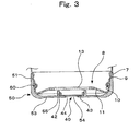
- the container bottom 8 of a bottomed cylindrical shape is disposed under the lower end of the body 4 through the intermediary of the overhang 7 (See Fig. 3).
- An engaging portion is circumferentially disposed at the upper end of peripheral bottom wall 9 of the bottom cylinder 8.
- a concave groove 10, in which to fit the O-ring 60, is circumferentially disposed below the engaging portion.
- An air intake 13 is opened in the outer layer 2 of this bottom cylinder 8 to allow outside air to flow in the void between the inner layer 3 and the outer layer 2.
- the second check valve mechanism 41 is disposed at the neck 6 of the container 1 so as to open or close the neck 6.
- a discharge section 20 is assembled with and fitted to the neck 6 to accept the comb attachment 72 although this comb attachment 72 may also be directly fitted into the neck 6 of the container 1 without using the discharge section 20.
- the second check valve mechanism 41 comprises a ring 42 and a disc-shaped valve 44, which is connected to the ring 42 and connectors 43 and is moved up or down, with the connectors 43 being fixed to the ring 42 at the outer ends to serve as rear anchors.
- the second check valve mechanism 41 also comprises an internal stopper 30, which is a fitting cylinder for fitting the second check valve mechanism into the container neck 6.
- the internal stopper 30 comprises an opening cylinder 31, which has top surface 32 and is suspended inside the container neck 6, a locking cylinder 34, which is suspended outwardly from the top surface and is fitted around the neck 6 by the engagement with the catching groove and the peripheral projecting ridge of the neck 6, and a joining cylinder 35, which stands up from the periphery of the top surface 32.
- Projected locking ridge segments are formed on the inner wall of the joining cylinder 35 to fix the upper surface of the ring 42 and to prevent the check valve mechanism 41 from escaping upward.
- the ring 42 is tightly fitted to the top surface 32 inside the joining cylinder 35, and in this configuration, the check valve 44 comes in tight contact with the top surface 32 and closes the mouth of the opening cylinder 31 and the container neck 6 in a manner that makes it impossible for the contents to flow back and for outside air to creep into the container.
- the discharge section 20 comprises an fitting cylinder 22, which is tightly fitted into the joining cylinder 35 of the internal stopper 30, an attaching cylinder 21 having a thread groove, which is notched on the inner wall and is engaged with the screw thread of the container neck 6, an outer wall 27, which is suspended from the shoulder 23 of the discharge section 20 to cover the container neck 6 from the outside, and a discharge cylinder 24 that forms the flow path 29 for the contents.
- the discharge cylinder 24 is provided with a brim portion, an inner cylinder 28 extending upward from the edge of the brim portion, and an inner peripheral catching ridge disposed at a level above the inner cylinder 28.
- a comb attachment 72 having plural teeth 73 is tightly fitted to the discharge cylinder 24.
- This comb attachment 72 comprises a comb spine 75, the inside of which forms the discharge passage 76 connected to the flow path 29 of the discharge section 20, an inserting portion 77 extending downward from the lower end of this spine 75, the plural teeth 73 that stand on one side of the spine 75 in a row and at equal intervals, and plural discharge holes 74 for discharging the contents into the interspaces of the teeth 73 as soon as the contents flow through the discharge passage 76 and reach the holes 74.
- the position of the discharge holes 65 is not limited to the interspaces of the teeth 61.
- Each tooth 73 may also be provided with an inside discharge passage 76 reaching the middle point of the tooth height, and a discharge hole may be disposed at the middle point of the tooth height and in the direction of the row of teeth. Or, the discharge holes 74 may be disposed at any position as long as the contents can be applied onto the hair through the teeth 73.
- the inserting portion 77 of the comb attachment 72 is tightly fitted into the inner cylinder 28 of the discharge cylinder 24. At that time, the peripheral catching ridge on the outer wall of the inserting portion 77 is engaged with the inner peripheral catching ridge on the inner wall of the discharge cylinder 24 so that the tight fitting would enhance the sealability of the discharge section 20 and the comb attachment 72.
- the base cup 50 a cylinder having the bottom of its own, comprises a cylindrical wall 51, which is fitted around the peripheral wall of the bottom cylinder 8 of the container 1, and also comprises the cup bottom plate 53, which is provided with an air hole 54 through which outside air flows in.
- An inner peripheral locking ridge is disposed in the upper part of the inner peripheral surface of the cylindrical wall 51 and is engaged with the engaging portion on the peripheral wall 9 of the bottom cylinder 8.
- a valve-fitting cylinder 55 is disposed so as to stand around the air hole 54 of the base cup 50 and to fix and retain the first check valve mechanism 40 that opens or closes the air hole 54.
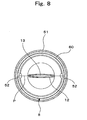
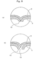
- Fig. 8 is a cross-sectional view taken from line X-X of Fig. 2 showing the bottom of the container 1 in the state in which the base cup 50 has been fitted around the bottom cylinder 8.
- the cylindrical wall 51 of the base cup 50 has an elliptic shape, with the axis on the parting line P being longer than the axis perpendicular to the parting line P.
- the pressing mechanism 52 has a cylindrical shape with a diameter shorter than the long axis along the parting line P of the bottom plate 13.
- the pinch-off portion 12 of the inner layer 3 and the outer layer 2 that have been sealed together is formed in a ridge along the parting line P and is disposed in the center of the bottom plate 11, which is the underside of the bottom cylinder 8 of the container 1.
- the cylindrical wall 51 having the pressing mechanism 52 is forcibly fitted around the bottom cylinder 8 of the container 1.
- the pressing mechanism 52 pushes the pinch-off portion 12 along the parting line P so as to open a slit in the pinch-off portion 12. This open slit is used as the air intake 13.
- the air intake 13 can be formed in the bottom cylinder 8 in the processing step of fitting the base cup 50 around the bottom cylinder 8 of the container 1. This step reduces the number of processes and increases productivity.
- the base cup 50 having the bottom of its own is fitted around the container bottom cylinder 8 for the reinforcement thereof.
- the base cup 50 serves as the outer shell to enhance the mechanical strength of the bottom cylinder 8, without causing any inconvenience, such as the degraded sitting function.
- the first check valve mechanism 40 comprises a ring 42, which is fitted tightly in the valve-fitting cylinder 55 of the base cup 50, and also comprises a disc-shaped valve 44, which is connected to this ring 42 and connectors 43 and comes in close contact with the cup bottom plate 53 to cover the air hole 54 opened in the bottom plate 53.
- the valve 44 acts as a check valve as it is moved up or down, with the connectors 43 being fixed to the ring 42 at the outer ends to serve as rear anchors.
- the inside of the inner layer 3 is always pressurized by the squeeze of the body 4 of the container 1. Then, the container neck 6 is opened by the function of the second check valve mechanism 41, and the contents pass through the flow path 27 of the discharge section 20 and through the discharge passage 76 of the comb attachment 72, and are discharged from the discharge holes 74.
- the contents such as a hair dye, can be applied to the hair by combing the teeth 73 through the hair.
- the inner layer 3 changes from the pressurized state to the depressurized state due to the recovery of the outer layer 2, and outside air and the contents that have passed by the second check valve mechanism 41 tend to be sucked into the inside of the inner layer 3. Since, at that time, the valve 44 acts to close the container neck 6 by the function of the second check valve mechanism 41, outside air is not sucked in, nor the contents flow back into the inside of the inner layer 3.
- the outer layer 2 When the body 4 is released from the pressure of a squeeze, the outer layer 2 begins restoring its original shape due to the resilient recovering force.
- the valve 44 of the first check valve mechanism 40 which has closed the air hole 54, moves up or down, with the connectors being fixed at the outer ends to serve as rear anchors, and opens the air hole 54 of the base cup 50. Outside air is introduced into the air intake 13 through this air hole 54, and flows into the void between the outer layer 2 and the inner layer 3. As a result, the outer layer 2 quickly restores its original shape.
- the second check valve mechanism 50 acts to close the air hole 54, and prevents the backflow of the air that has been introduced into the void between the outer layer 2 and the inner layer 3.
- the base cup 50 is tightly fitted around the bottom cylinder 8 through the intermediary of the O-ring 60 disposed in the concave groove 10 on the bottom cylinder 8 of the container 1. Because of this O-ring 60, air tightness increases for the gap between the bottom cylinder 8 and the base cup 50. The air introduced from the air hole 54 does not escape outside through this gap.
- the second check valve mechanism 41 opens the container neck 6 again, and the contents are discharged smoothly from the discharge holes 74 and can be applied to the hair by combing the hair with the teeth 73 of the comb.
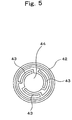
- Fig. 5 is a plan view showing an embodiment of the first check valve mechanism 40 and the second check valve mechanism 41.
- Each mechanism comprises a ring 42 fitted tightly into the cylindrical wall 51 of the base cup 50 or the joining cylinder 35 of the internal stopper 30, and also comprises a disc-like valve 44, which is connected to this ring 42 and connectors 43 and is in close contact with the top surface of the cup bottom plate 53, in which the air hole 54 is opened, or with the top surface 32 of the internal stopper 30.
- the valve 44 acts as a check valve as it moves up or down, with the connectors being fixed at outer ends to serve as rear anchors.
- Fig. 6 shows a structural embodiment of both check valve mechanisms 40, 41.
- Both of the check valves 40, 41 can also be in the structure of a slit valve, which comprises a cross-shaped slit 49 in a slit plate 47 disposed under the ring 42 serving as the fitting portion. This slit 49 is placed to cover the air hole 54 of the base cup 50 or the opening formed by the internal stopper 30.
- both check valves can be of any structure other than described above as far as they function as check valves.
- Fig. 10 shows the structure of the discharge container in the second embodiment of this invention.
- the discharge container comprises the container 1 of the same structure as in the first embodiment, the discharge section 20 fitted into the neck 6 of the container 1, the second check valve 41 in the form of a headed cylinder 48 fitted into the discharge section 20, the base cup 50, and the first check valve mechanism 40.
- a cap 80 is put on the discharge section 20 and is screwed on the neck 6 of the container 1.
- the discharge section 20 comprises a fitting cylinder 22 to be fitted into the neck 6, a top plate 23 disposed around the peripheral wall of the fitting cylinder 22, a discharge cylinder 24 disposed on the top plate 23 so as to reduce its diameter in the upward direction and connected to the container neck 6 to form the flow path 29 for the contents, and a discharge port 25 opened in the head to discharge the contents in drops.
- the second check valve mechanism 41 is disposed in the flow path 29 of the discharge section 20. As shown in Fig. 10, the second check valve mechanism 41 is a slit valve comprising a headed attaching cylinder 48 of a bombshell shape fitted in the discharge section 20 that forms the flow path 29 and also comprising a slit 49 disposed at the top of the headed attaching cylinder 48.
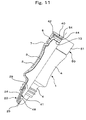
- Fig. 11 is a schematic diagram showing the movement of the discharge container experienced when the body 4 of the container 1 is squeezed and deformed. With a squeeze given to the body 4, the inside of the inner layer 3 is pressurized, as shown in Fig. 11. Then, there opens the slit 49 of the second check valve mechanism 41, which is the slit valve, and eye drops, the contents, are discharged in drops from the discharge port 25.
- the second check valve mechanism 41 which is the slit valve, and eye drops, the contents
- the inner layer 3 changes from the pressurized state to the depressurized state, and outside air tends to be sucked into the inside of the inner layer 3. Since, at that time, the second check valve mechanism 41 acts to close the slit 49, outside air is not sucked in, nor the contents flow back.
- the outer layer 2 resiliently restores its original shape due to the ability of self-shape retention.
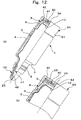
- the inner layer 3 does not suck in outside air, but remains deflated and deformed with the decrease in the contents. Therefore, a void is formed between the outer layer 2 that returns to its original shape and the inner layer 3 that remains deflated. (See Fig. 12(a).)
- the void falls into a reduced pressure condition. Then, the valve 44 of the first check valve mechanism 40 moves up or down, with the connectors being fixed at the outer ends to serve as rear anchors, and opens the air hole 54 of the base cup 50. Outside air is introduced into the air intake 13 through this air hole 54, and flows into the void between the outer layer 2 and the inner layer 3. (See Fig. 12(b).)
- the first check valve mechanism 40 operates, and the valve 44 closes the air hole 54.
- the first check valve mechanism 40 blocks up the connection between the air intake 13 and outside air, and at the same time, prevents the backflow of the air that has been introduced into the void between the outer layer 2 and the inner layer 3.
- the squeeze of the outer layer 2 pressurizes steadily the contents inside the deflated and deformed inner layer 3 by way of the air existing between the outer layer 2 and the inner layer 3. Then, the slit 49 of the second check valve mechanism 41 opens to allow the contents to be discharged from the discharge port 25.
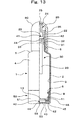
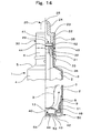
- Fig. 13 is a front elevational view of the discharge container in the third embodiment of this invention, with the right half being illustrated in a longitudinal section.
- the internal stopper 30 is fitted into the neck of the container 1, and is provided with a rod 36, which extends down to a nearly middle point in the vertical direction of the container 1.
- the rod 36 serves to maintain a passageway for the flow of contents through the opening cylinder, the length of this rod 36 is not limited to the middle point of the container in the vertical direction, but can be close to the lower end of the stopper 30, or the rod may have a length reaching the bottom cylinder 8.
- the internal stopper 30 comprises the inletting cylinder 31, which has top surface 32 and which is fitted into the neck 6 of the container 1 to make the internal stopper 30 assembled and fitted to the neck 6; the opening cylinder 33, which is suspended from the innermost portion of the top surface 32 of the inletting cylinder 31; the rod 36, which has a cross pattern at the upper end and is disposed under the opening cylinder 33 to form a passageway to allow the liquid contents to flow through this opening cylinder 33 (See Fig. 15); and the intermediary cylinder 35 that stands up from the peripheral edge of the top surface 32.
- the upper end of the rod 36 is not limited to the cross pattern, but can be straight lines or a more complicated grid pattern, and the rod 36 may have any shape at the upper end.
- the discharge section 20 is fitted tightly in the neck 6 of the container 1 when the fitting cylinder 22 is fitted into the intermediary cylinder 35 of the internal stopper 30.
- the rod 36 secures the flow path 29 for the discharge of the contents even if the deflation and deformation of the inner layer 3 is in progress with the decrease in the contents.
- the second check valve mechanism 41 of a structure shown in Fig. 5 is disposed in the intermediary cylinder 35 of the internal stopper 30.
- the first check valve mechanism 40 shown in Fig. 5 is disposed inside the base cup 50 and is molded integrally from a soft, resilient material, together with a gasket 46 standing up from the upper end of the ring 42 by way of an outer brim 45.
- the gasket 46 is fitted around the wall 9 of the bottom cylinder 9 of the container 1 and is also fitted in the cylindrical wall 51 of the base cup 50. Since the gasket 46 made of a soft, resilient material is sandwiched between the wall 9 of the bottom cylinder 8 and the cylindrical wall 51, outside air fails to pass the gap between these portions, and the air introduced from the air hole 54 does not escape outside through the gap.
- the first check valve mechanism 40 performs its check valve function so that air introduce through the air hole 54 is not allowed to escape outside, but is allowed to retained in the void between the deflated and deformed inner layer 3 and the outer layer 2. (See Fig. 14.)
- the first check valve 40 operates so as to prevent the backflow of air from the air hole 54, without allowing air to escape through the gap of the base cup 50, which is fitted around the bottom cylinder 8 of the container 1.
- the squeeze of the outer layer 2 ensures that the contents are pressurized and that smooth discharge operations of the discharge container can be maintained.
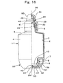
- Fig. 16 shows the discharge container in the fourth embodiment of this invention.
- An enlarged overhang 7 is disposed on the bottom cylinder 8 of the container 1.
- An outer cylinder 56 surrounds the cylindrical wall 51 of the base cup 50 and stands up from the periphery of the cup bottom plate 53 in such a way that the wall of the outer cylinder 56 supports the peripheral edge of the overhang 7 from underneath.
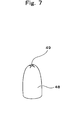
- first check valve mechanism 40 comprising the ring 42 and the slit plate 47 having the slit 49, as shown in Fig 6, and the second check valve mechanism 41 comprising the headed cylinder 48, as shown in Fig. 7.
- the entire structure is simple, and the discharge container of a fully small size can be obtained at a low cost.
- the base cup 50 shows an improved reinforcing function as the shell.
- the bottom cylinder 8 of the container 1 is mechanically stabilized, and experiences no inconvenience of buckling.
- Fig. 17 is a front elevational view of the discharge container attached with an applicator 70 in another embodiment of this invention.
- a comb attachment 72 having teeth 73 is disposed on the topside of the comb spine 75.
- Fig. 18 shows an applicator 70 in still another embodiment to be fitted to the discharge container of this invention.
- a screw thread is notched on the outer surface of the intermediary cylinder 35 of the internal stopper 30.
- the discharge section 20 comprises a fitting cylinder 22, which is suspended to fit into the intermediary cylinder 35, and also comprises a connecting cylinder 21, which is provided with a locking ridge to be screwed together with the screw thread on the intermediary cylinder 35 on contact with the fitting cylinder 22 and the top plate 23.
- Inside this fitting cylinder 22 there is a tapered cylinder 26 of a hopper type, which is centrally disposed.
- Discharge port 25 is located in the center and at the lowest point of this tapered cylinder 26, which is provided with a brush 71 with hair implant on the upper tapered surface.
- the applicator 70 may be directly fitted to the neck 6 of the container 1, or the applicator can take various other shapes, such as those described below.
- the applicator 70 Since the applicator 70 is disposed at the discharge section 20, the contents can be directly applied to the target area by means of the brush applicator 70 when the contents are discharged through the discharge port 25 by squeezing the container 1. Thus, the discharge container has improved convenience of use and ease of operation.
- the applicator 70 is not limited to the brush type, but also includes porous sponge, a semispherical head having a massaging effect, and the like. It is desirable to have an applicator that is effective and suitable for the intended purpose of the contents to be put in the discharge container.
- the first check valve mechanism operates to fill air smoothly in the void between the outer layer and the inner layer that has broken away from the outer layer. Since the outer layer quickly restores its original shape, it is possible to maintain good outer appearance of the container.
- the container can be made to have its stable bottom shape because the container bottom is reinforced with the base cup, which is fitted around the bottom cylinder of the container.
- the second check valve acts to discharge the contents with the squeeze and deformation of the container.
- the second check valve prevents the backflow or the contents and the entry of outside air. Since the void between the outer layer and the deformed inner layer is filled with air because of the function of the first check valve, the squeeze of the outer layer ensures that the contents are pressurized and discharged smoothly to the last drop.
- a discharge container having ease of discharge operation.
- the base cup is fitted around the bottom cylinder of the container through the intermediary of the O-ring, which makes tight fitting easy and reliable.
- an air hole is disposed in the base cup bottom, which is tightly fitted around the bottom cylinder of the container.
- the base cup stably reinforces the bottom cylinder of the container.
- the first check valve mechanism can be fitted to the base cup favorably and easily.
- elasticity of the connectors can be set so freely that the check valve mechanisms are able to move at any desired sensitivity. Thus, smooth and favorable operation is available for the discharge container.
- the check valves can be obtained easily at a less expensive cost because the check valve mechanisms have a simple configuration.
- the gasket is an essential part of the first check valve mechanism, and can be used to fit the base cup tightly to the container. Because of this gasket, the configuration can be simplified for the tight fitting of base cup to the container.
- the air intake can be formed simply and properly in the bottom of the discharge cylinder, without causing the mechanical strength to be lowered.
- the air intake can be opened in the bottom of the container by fitting the base cup to the container. Since no additional work process is required to open the air intake, the discharge container production processes can be simplified.
- the discharge section fitted to the neck of the container is free to form any desired discharge port. Therefore, it is possible to allow the discharge container to respond flexibly to the purpose of use.
- the discharge section having the discharge port at the tip can be formed into a slim cylinder, which is suitable to discharge the contents in drops.
- the discharge container of this invention can be used favorably as an eyedropper.
- the contents are discharged from the container and can be applied easily and directly to the intended place by utilizing the applicator.
- the contents are discharged in the interspaces of the teeth, and can be applied to the hair by passing the comb through the hair.
- the contents becomes quite simple to apply the contents to the hair.
- plural teeth are disposed on one side of the comb spine.
- the contents can be applied to the hair by holding the container body with a hand and combing the teeth through the hair in the same way as using an ordinary comb.
- the teeth are disposed on top of the comb spine. This makes it easy to mold the comb integrally as the one having the teeth and the discharge holes for discharging the contents into the interspaces of the teeth.
- a brush is used as the applicator.
- the discharged contents can be applied directly to the surface by using this brush.
- the second check valve mechanism can be fitted properly and easily in the configuration using the discharge section.
- the structure can be much more simplified to fit the second check valve mechanism.
- the discharge and consumption of the contents can be favorably maintained to the last because the contents can be steadily and smoothly discharged to the last drop.
- the second check valve mechanism of quite a simple structure, and there can be also provided a check valve of quite a small diameter.
- the second check valve mechanism it becomes possible for the second check valve mechanism to be located at a position fully close to the discharge port that has been opened at the tip of a slim discharge cylinder. It is also possible for the contents remaining outside the second check valve mechanism to be reduced to a much less amount.
- the outer layer of the container quickly restores its original shape because of the function of the first check valve. Even if the container is of a small size, it has the ease of operation. Furthermore, because the second check valve prevents outside air from creeping inside the inner layer, the container is highly sanitary and most suitable for use as an eyedropper.
Landscapes
- Engineering & Computer Science (AREA)
- Mechanical Engineering (AREA)
- Health & Medical Sciences (AREA)
- Hematology (AREA)
- Pharmacology & Pharmacy (AREA)
- Life Sciences & Earth Sciences (AREA)
- Animal Behavior & Ethology (AREA)
- General Health & Medical Sciences (AREA)
- Public Health (AREA)
- Veterinary Medicine (AREA)
- Closures For Containers (AREA)
- Containers And Packaging Bodies Having A Special Means To Remove Contents (AREA)
Applications Claiming Priority (5)
| Application Number | Priority Date | Filing Date | Title |
|---|---|---|---|
| JP2002129195A JP3994147B2 (ja) | 2002-04-30 | 2002-04-30 | 櫛歯容器 |
| JP2002129195 | 2002-04-30 | ||
| JP2002128800A JP4003937B2 (ja) | 2002-04-30 | 2002-04-30 | 注出容器 |
| JP2002128800 | 2002-04-30 | ||
| PCT/JP2003/005511 WO2003093132A1 (fr) | 2002-04-30 | 2003-04-30 | Recipient verseur |
Publications (3)
| Publication Number | Publication Date |
|---|---|
| EP1500603A1 true EP1500603A1 (fr) | 2005-01-26 |
| EP1500603A4 EP1500603A4 (fr) | 2007-04-11 |
| EP1500603B1 EP1500603B1 (fr) | 2011-06-08 |
Family
ID=29405302
Family Applications (1)
| Application Number | Title | Priority Date | Filing Date |
|---|---|---|---|
| EP03725703A Expired - Lifetime EP1500603B1 (fr) | 2002-04-30 | 2003-04-30 | Recipient verseur |
Country Status (7)
| Country | Link |
|---|---|
| US (1) | US7293674B2 (fr) |
| EP (1) | EP1500603B1 (fr) |
| KR (1) | KR100921133B1 (fr) |
| CN (1) | CN100423996C (fr) |
| AU (1) | AU2003231559A1 (fr) |
| TW (1) | TWI270512B (fr) |
| WO (1) | WO2003093132A1 (fr) |
Cited By (1)
| Publication number | Priority date | Publication date | Assignee | Title |
|---|---|---|---|---|
| WO2007032660A1 (fr) * | 2005-09-15 | 2007-03-22 | 4Sight Innovation B.V. | Dispositif pour l'application d'applications cosmetiques |
Families Citing this family (13)
| Publication number | Priority date | Publication date | Assignee | Title |
|---|---|---|---|---|
| WO2005063165A1 (fr) * | 2003-12-26 | 2005-07-14 | Santen Pharmaceutical Co., Ltd. | Recipient de stockage de liquide a filtre de fond |
| JP5267901B2 (ja) * | 2007-06-29 | 2013-08-21 | 株式会社吉野工業所 | ダイレクトブロー成形法による合成樹脂製二重容器 |
| JP4981739B2 (ja) * | 2008-04-24 | 2012-07-25 | 凸版印刷株式会社 | バリア性を有する蓋 |
| KR200473973Y1 (ko) * | 2012-08-16 | 2014-08-14 | (주)아모레퍼시픽 | 실리콘계열의 마스카라 브러시 |
| CA2916039C (fr) * | 2013-06-28 | 2017-08-29 | Yoshino Kogyosho Co., Ltd. | Recipient a double paroi |
| KR200479136Y1 (ko) | 2014-06-19 | 2016-01-04 | (주)영진팩 | 체크 밸브 구조를 갖는 이중 용기 |
| JP6512800B2 (ja) * | 2014-11-28 | 2019-05-15 | 株式会社吉野工業所 | 泡吐出可能な二重容器 |
| USD821030S1 (en) * | 2016-06-14 | 2018-06-19 | Daphnee Paul | Comb with integrated liquid dispenser |
| JP2020511185A (ja) * | 2016-12-15 | 2020-04-16 | エヌエスイー プロダクツ インコーポレイテッド | 毛を有する皮膚に流体を局所的に塗布するための装置と方法 |
| KR102523963B1 (ko) | 2020-01-03 | 2023-04-21 | 이화여자대학교 산학협력단 | 이종 약물을 혼합하기 위한 안약 용기 |
| CN218278928U (zh) * | 2022-09-08 | 2023-01-13 | 长风药业股份有限公司 | 一种雾化梳 |
| US20250042595A1 (en) * | 2023-08-04 | 2025-02-06 | Canon Kabushiki Kaisha | Liquid storage bottle |
| US12409984B2 (en) | 2023-11-20 | 2025-09-09 | Weld-On Adhesives, Inc. | Reversible cap for adhesive containers |
Family Cites Families (24)
| Publication number | Priority date | Publication date | Assignee | Title |
|---|---|---|---|---|
| JPS5084376A (fr) * | 1973-11-28 | 1975-07-08 | ||
| US4209027A (en) * | 1974-06-21 | 1980-06-24 | Shila Morganroth | Hair treatment devices and packaging therefor |
| JPH0615893Y2 (ja) * | 1989-10-04 | 1994-04-27 | 誠一 北林 | 指圧ポンプ式噴出容器 |
| US5056689A (en) | 1990-01-08 | 1991-10-15 | Ciba-Geigy Corporation | Apparatus for removing components from solutions |
| US5301838A (en) * | 1991-01-23 | 1994-04-12 | Continental Pet Technologies, Inc. | Multilayer bottle with separable inner layer and method for forming same |
| AU3128493A (en) * | 1991-11-20 | 1993-06-15 | Procter & Gamble Company, The | Resilient squeeze bottle with an inner receptacle which inverts upon emptying |
| FR2690674B1 (fr) | 1992-04-30 | 1996-01-26 | Oreal | Distributeur de produit a poche deformable. |
| JP2595396Y2 (ja) * | 1993-10-14 | 1999-05-31 | 武内プレス工業株式会社 | 多層押圧式容器 |
| JP3688373B2 (ja) | 1995-12-22 | 2005-08-24 | 株式会社吉野工業所 | 押出注出可能とした積層剥離容器 |
| FR2753437B1 (fr) | 1996-09-16 | 1998-10-30 | Oreal | Conditionnement pour produit de consistance liquide a pateuse |
| EP2245954B1 (fr) * | 1998-06-30 | 2014-06-04 | Kao Corporation | Conteneur avec applicateur |
| US5913314A (en) * | 1998-10-05 | 1999-06-22 | Garrett; Michelle R. | Combination salon tool device |
| JP2000177767A (ja) | 1998-12-15 | 2000-06-27 | Kao Corp | 塗布容器 |
| JP2000281112A (ja) | 1999-03-26 | 2000-10-10 | Pentel Corp | 吐出容器 |
| JP2001106262A (ja) * | 1999-10-05 | 2001-04-17 | Kyoraku Co Ltd | 押出し容器 |
| JP2001106261A (ja) * | 1999-10-05 | 2001-04-17 | Sanyo Electric Co Ltd | 原料の保存容器 |
| JP4485627B2 (ja) | 1999-10-08 | 2010-06-23 | 大成化工株式会社 | 積層剥離ボトル、並びに、ポンプ容器 |
| JP4586223B2 (ja) * | 1999-11-19 | 2010-11-24 | 大成化工株式会社 | 吐出容器 |
| JP3817600B2 (ja) | 2000-07-31 | 2006-09-06 | 株式会社吉野工業所 | 合成樹脂製壜体 |
| JP4532703B2 (ja) | 2000-08-01 | 2010-08-25 | ホーユー株式会社 | 櫛付き二重容器 |
| JP4443013B2 (ja) * | 2000-08-01 | 2010-03-31 | 花王株式会社 | 二重容器用キャップ |
| JP4580524B2 (ja) | 2000-09-12 | 2010-11-17 | 株式会社日本点眼薬研究所 | フィルター付き吐出容器 |
| US6719173B2 (en) | 2002-03-25 | 2004-04-13 | Owens-Brockway Plastic Products Inc. | Multilayer container package for dispensing a liquid product |
| US6675812B1 (en) * | 2002-05-07 | 2004-01-13 | Lien L. Wiley | Dispenser with comb or brush with optional sponge for cream, lotion, gel or liquid |
-
2003
- 2003-04-30 CN CNB038007568A patent/CN100423996C/zh not_active Expired - Fee Related
- 2003-04-30 EP EP03725703A patent/EP1500603B1/fr not_active Expired - Lifetime
- 2003-04-30 AU AU2003231559A patent/AU2003231559A1/en not_active Abandoned
- 2003-04-30 KR KR1020047000711A patent/KR100921133B1/ko not_active Expired - Fee Related
- 2003-04-30 US US10/505,134 patent/US7293674B2/en not_active Expired - Fee Related
- 2003-04-30 TW TW092110195A patent/TWI270512B/zh not_active IP Right Cessation
- 2003-04-30 WO PCT/JP2003/005511 patent/WO2003093132A1/fr not_active Ceased
Cited By (1)
| Publication number | Priority date | Publication date | Assignee | Title |
|---|---|---|---|---|
| WO2007032660A1 (fr) * | 2005-09-15 | 2007-03-22 | 4Sight Innovation B.V. | Dispositif pour l'application d'applications cosmetiques |
Also Published As
| Publication number | Publication date |
|---|---|
| TWI270512B (en) | 2007-01-11 |
| CN1537068A (zh) | 2004-10-13 |
| EP1500603B1 (fr) | 2011-06-08 |
| WO2003093132A1 (fr) | 2003-11-13 |
| KR100921133B1 (ko) | 2009-10-12 |
| CN100423996C (zh) | 2008-10-08 |
| TW200307630A (en) | 2003-12-16 |
| AU2003231559A1 (en) | 2003-11-17 |
| US7293674B2 (en) | 2007-11-13 |
| KR20040103892A (ko) | 2004-12-09 |
| US20050155981A1 (en) | 2005-07-21 |
| EP1500603A4 (fr) | 2007-04-11 |
Similar Documents
| Publication | Publication Date | Title |
|---|---|---|
| US7293674B2 (en) | Discharge container having a squeezable and deformable | |
| US5379919A (en) | Unit for dispensing at least one fluid product, in particular, a cosmetic or pharmaceutical product, having a pressure actuated, self-sealing closure outlet | |
| JP4129811B2 (ja) | 注出容器 | |
| JPH0924980A (ja) | 液体、ゲル、又はペーストを収容して小出しするための、ドーム形アプリケータ付き装置 | |
| KR101775945B1 (ko) | 체크밸브가 구비된 역류방지 스포이드 용기 | |
| US7299945B2 (en) | Discharge container with one-way valves | |
| KR102209696B1 (ko) | 선택적 토출이 가능한 두피 관리용 화장품용기 | |
| US20020066749A1 (en) | Dispensing device and methods | |
| KR100785915B1 (ko) | 분배장치 및 이를 이용한 액상물 분배 용기 | |
| KR102382964B1 (ko) | 스포이드가 구비된 용기 | |
| TW200404611A (en) | Delivering device | |
| JP2004001780A (ja) | 注出容器 | |
| JP2023081295A (ja) | 注出容器 | |
| US20190152680A1 (en) | Container for discharging liquid | |
| CN215884672U (zh) | 一种出料效果好的化妆品包装瓶 | |
| JP3993487B2 (ja) | 流動体のチューブ型容器 | |
| US20240066540A1 (en) | Fluid dispenser with priming means | |
| JP2004187878A (ja) | 液体化粧料容器 | |
| KR20230028645A (ko) | 듀오믹스 기능을 가지는 화장품 용기용 캡 | |
| JP2001010683A (ja) | ポンプ付液注出容器 | |
| KR20220106375A (ko) | 약액 디스펜서 | |
| KR200415000Y1 (ko) | 스퀴즈 용기 | |
| KR100789665B1 (ko) | 스퀴즈 용기 | |
| JPH10139080A (ja) | 内容物吐出容器のスリットバルブ | |
| KR20070047941A (ko) | 디스펜싱 밸브 클로우져 |
Legal Events
| Date | Code | Title | Description |
|---|---|---|---|
| PUAI | Public reference made under article 153(3) epc to a published international application that has entered the european phase |
Free format text: ORIGINAL CODE: 0009012 |
|
| 17P | Request for examination filed |
Effective date: 20040906 |
|
| AK | Designated contracting states |
Kind code of ref document: A1 Designated state(s): AT BE BG CH CY CZ DE DK EE ES FI FR GB GR HU IE IT LI LU MC NL PT RO SE SI SK TR |
|
| AX | Request for extension of the european patent |
Extension state: AL LT LV MK |
|
| RIC1 | Information provided on ipc code assigned before grant |
Ipc: A46B 11/00 20060101ALI20070116BHEP Ipc: A45D 24/26 20060101ALI20070116BHEP Ipc: A45D 24/22 20060101AFI20070116BHEP Ipc: B65D 83/00 20060101ALI20070116BHEP |
|
| A4 | Supplementary search report drawn up and despatched |
Effective date: 20070313 |
|
| 17Q | First examination report despatched |
Effective date: 20090520 |
|
| GRAP | Despatch of communication of intention to grant a patent |
Free format text: ORIGINAL CODE: EPIDOSNIGR1 |
|
| GRAS | Grant fee paid |
Free format text: ORIGINAL CODE: EPIDOSNIGR3 |
|
| GRAA | (expected) grant |
Free format text: ORIGINAL CODE: 0009210 |
|
| AK | Designated contracting states |
Kind code of ref document: B1 Designated state(s): DE FR GB |
|
| REG | Reference to a national code |
Ref country code: GB Ref legal event code: FG4D |
|
| REG | Reference to a national code |
Ref country code: DE Ref legal event code: R096 Ref document number: 60337330 Country of ref document: DE Effective date: 20110721 |
|
| PLBE | No opposition filed within time limit |
Free format text: ORIGINAL CODE: 0009261 |
|
| STAA | Information on the status of an ep patent application or granted ep patent |
Free format text: STATUS: NO OPPOSITION FILED WITHIN TIME LIMIT |
|
| 26N | No opposition filed |
Effective date: 20120309 |
|
| REG | Reference to a national code |
Ref country code: DE Ref legal event code: R097 Ref document number: 60337330 Country of ref document: DE Effective date: 20120309 |
|
| REG | Reference to a national code |
Ref country code: FR Ref legal event code: PLFP Year of fee payment: 13 |
|
| REG | Reference to a national code |
Ref country code: FR Ref legal event code: PLFP Year of fee payment: 14 |
|
| REG | Reference to a national code |
Ref country code: FR Ref legal event code: PLFP Year of fee payment: 15 |
|
| REG | Reference to a national code |
Ref country code: FR Ref legal event code: PLFP Year of fee payment: 16 |
|
| PGFP | Annual fee paid to national office [announced via postgrant information from national office to epo] |
Ref country code: FR Payment date: 20190313 Year of fee payment: 17 |
|
| PGFP | Annual fee paid to national office [announced via postgrant information from national office to epo] |
Ref country code: DE Payment date: 20190416 Year of fee payment: 17 |
|
| PGFP | Annual fee paid to national office [announced via postgrant information from national office to epo] |
Ref country code: GB Payment date: 20190424 Year of fee payment: 17 |
|
| REG | Reference to a national code |
Ref country code: DE Ref legal event code: R119 Ref document number: 60337330 Country of ref document: DE |
|
| PG25 | Lapsed in a contracting state [announced via postgrant information from national office to epo] |
Ref country code: DE Free format text: LAPSE BECAUSE OF NON-PAYMENT OF DUE FEES Effective date: 20201103 Ref country code: FR Free format text: LAPSE BECAUSE OF NON-PAYMENT OF DUE FEES Effective date: 20200430 |
|
| GBPC | Gb: european patent ceased through non-payment of renewal fee |
Effective date: 20200430 |
|
| PG25 | Lapsed in a contracting state [announced via postgrant information from national office to epo] |
Ref country code: GB Free format text: LAPSE BECAUSE OF NON-PAYMENT OF DUE FEES Effective date: 20200430 |