EP1500851A2 - Appareil pour ouvrir et fermer un couvercle - Google Patents
Appareil pour ouvrir et fermer un couvercle Download PDFInfo
- Publication number
- EP1500851A2 EP1500851A2 EP04017389A EP04017389A EP1500851A2 EP 1500851 A2 EP1500851 A2 EP 1500851A2 EP 04017389 A EP04017389 A EP 04017389A EP 04017389 A EP04017389 A EP 04017389A EP 1500851 A2 EP1500851 A2 EP 1500851A2
- Authority
- EP
- European Patent Office
- Prior art keywords
- cover
- reducer
- torque
- output portion
- output
- Prior art date
- Legal status (The legal status is an assumption and is not a legal conclusion. Google has not performed a legal analysis and makes no representation as to the accuracy of the status listed.)
- Granted
Links
Images


Classifications
-
- F—MECHANICAL ENGINEERING; LIGHTING; HEATING; WEAPONS; BLASTING
- F16—ENGINEERING ELEMENTS AND UNITS; GENERAL MEASURES FOR PRODUCING AND MAINTAINING EFFECTIVE FUNCTIONING OF MACHINES OR INSTALLATIONS; THERMAL INSULATION IN GENERAL
- F16J—PISTONS; CYLINDERS; SEALINGS
- F16J13/00—Covers or similar closure members for pressure vessels in general
-
- F—MECHANICAL ENGINEERING; LIGHTING; HEATING; WEAPONS; BLASTING
- F16—ENGINEERING ELEMENTS AND UNITS; GENERAL MEASURES FOR PRODUCING AND MAINTAINING EFFECTIVE FUNCTIONING OF MACHINES OR INSTALLATIONS; THERMAL INSULATION IN GENERAL
- F16J—PISTONS; CYLINDERS; SEALINGS
- F16J13/00—Covers or similar closure members for pressure vessels in general
- F16J13/16—Pivoted closures
- F16J13/18—Pivoted closures pivoted directly on the frame
-
- B—PERFORMING OPERATIONS; TRANSPORTING
- B65—CONVEYING; PACKING; STORING; HANDLING THIN OR FILAMENTARY MATERIAL
- B65D—CONTAINERS FOR STORAGE OR TRANSPORT OF ARTICLES OR MATERIALS, e.g. BAGS, BARRELS, BOTTLES, BOXES, CANS, CARTONS, CRATES, DRUMS, JARS, TANKS, HOPPERS, FORWARDING CONTAINERS; ACCESSORIES, CLOSURES, OR FITTINGS THEREFOR; PACKAGING ELEMENTS; PACKAGES
- B65D90/00—Component parts, details or accessories for large containers
- B65D90/10—Manholes; Inspection openings; Covers therefor
-
- F—MECHANICAL ENGINEERING; LIGHTING; HEATING; WEAPONS; BLASTING
- F16—ENGINEERING ELEMENTS AND UNITS; GENERAL MEASURES FOR PRODUCING AND MAINTAINING EFFECTIVE FUNCTIONING OF MACHINES OR INSTALLATIONS; THERMAL INSULATION IN GENERAL
- F16F—SPRINGS; SHOCK-ABSORBERS; MEANS FOR DAMPING VIBRATION
- F16F9/00—Springs, vibration-dampers, shock-absorbers, or similarly-constructed movement-dampers using a fluid or the equivalent as damping medium
-
- F—MECHANICAL ENGINEERING; LIGHTING; HEATING; WEAPONS; BLASTING
- F16—ENGINEERING ELEMENTS AND UNITS; GENERAL MEASURES FOR PRODUCING AND MAINTAINING EFFECTIVE FUNCTIONING OF MACHINES OR INSTALLATIONS; THERMAL INSULATION IN GENERAL
- F16H—GEARING
- F16H1/00—Toothed gearings for conveying rotary motion
- F16H1/28—Toothed gearings for conveying rotary motion with gears having orbital motion
- F16H1/32—Toothed gearings for conveying rotary motion with gears having orbital motion in which the central axis of the gearing lies inside the periphery of an orbital gear
-
- H—ELECTRICITY
- H10—SEMICONDUCTOR DEVICES; ELECTRIC SOLID-STATE DEVICES NOT OTHERWISE PROVIDED FOR
- H10P—GENERIC PROCESSES OR APPARATUS FOR THE MANUFACTURE OR TREATMENT OF DEVICES COVERED BY CLASS H10
- H10P72/00—Handling or holding of wafers, substrates or devices during manufacture or treatment thereof
- H10P72/04—Apparatus for manufacture or treatment
- H10P72/0441—Apparatus for sealing, encapsulating, glassing, decapsulating or the like
-
- Y—GENERAL TAGGING OF NEW TECHNOLOGICAL DEVELOPMENTS; GENERAL TAGGING OF CROSS-SECTIONAL TECHNOLOGIES SPANNING OVER SEVERAL SECTIONS OF THE IPC; TECHNICAL SUBJECTS COVERED BY FORMER USPC CROSS-REFERENCE ART COLLECTIONS [XRACs] AND DIGESTS
- Y10—TECHNICAL SUBJECTS COVERED BY FORMER USPC
- Y10T—TECHNICAL SUBJECTS COVERED BY FORMER US CLASSIFICATION
- Y10T74/00—Machine element or mechanism
- Y10T74/19—Gearing
- Y10T74/19023—Plural power paths to and/or from gearing
-
- Y—GENERAL TAGGING OF NEW TECHNOLOGICAL DEVELOPMENTS; GENERAL TAGGING OF CROSS-SECTIONAL TECHNOLOGIES SPANNING OVER SEVERAL SECTIONS OF THE IPC; TECHNICAL SUBJECTS COVERED BY FORMER USPC CROSS-REFERENCE ART COLLECTIONS [XRACs] AND DIGESTS
- Y10—TECHNICAL SUBJECTS COVERED BY FORMER USPC
- Y10T—TECHNICAL SUBJECTS COVERED BY FORMER US CLASSIFICATION
- Y10T74/00—Machine element or mechanism
- Y10T74/19—Gearing
- Y10T74/19555—Varying speed ratio
-
- Y—GENERAL TAGGING OF NEW TECHNOLOGICAL DEVELOPMENTS; GENERAL TAGGING OF CROSS-SECTIONAL TECHNOLOGIES SPANNING OVER SEVERAL SECTIONS OF THE IPC; TECHNICAL SUBJECTS COVERED BY FORMER USPC CROSS-REFERENCE ART COLLECTIONS [XRACs] AND DIGESTS
- Y10—TECHNICAL SUBJECTS COVERED BY FORMER USPC
- Y10T—TECHNICAL SUBJECTS COVERED BY FORMER US CLASSIFICATION
- Y10T74/00—Machine element or mechanism
- Y10T74/20—Control lever and linkage systems
- Y10T74/20576—Elements
- Y10T74/20582—Levers
Definitions
- the present invention relates to a cover activating device for opening and closing a cover of a container.
- an activating device for a cover of a container known is an apparatus in which the cover is disposed openably and closably on a container via an arm that is coupled so as to be rotatable integrally with a shaft rotatably supported by the container, and which comprises a gas spring for enabling the arm to be rotatable, and a worm gear for allowing the shaft to be rotatable (for example, see JP-A-2001-21039 (Page 3, Figs. 3 and 4)).
- the conventional activating device for a cover is configured by the gas spring for enabling the arm to be rotatable, and the worm gear for allowing the shaft to be rotatable, and hence has a problem in that the apparatus has a large size.
- the invention has been conducted in order to solve the problem of the conventional art. It is an object of the invention to provide an activating device for a cover which can be made smaller in size than a conventional apparatus.
- the activating device for a cover of the invention has a configuration wherein the apparatus comprises: a shaft unit which is supported by a case of a container having the case and a cover, and which has a rotary shaft; an arm unit which is coupled to the cover and the rotary shaft; and an actuator which drives the rotary shaft, the actuator comprises: a motor having a first output portion from which power is output; a first reducer having a first input portion which receives the power from the first output portion, and a second output portion from which power is output, the first reducer reducing the output of the motor; and a second reducer having a second input portion which receives the power from the second output portion, and a third output portion from which power is output to the rotary shaft, the second reducer reducing the output of the first reducer, and a reciprocal (R 2 ) of a reduction ratio of the second reducer is larger than a quotient which is obtained by dividing a product by a torque (T R1 ) that is required for rotating the second output portion when
- the apparatus can be made smaller in size than a conventional apparatus.
- the activating device for a cover of the invention has a configuration wherein each of the first reducer and the second reducer includes a differential gear reduction mechanism.
- the activating device for a cover of the invention closing of the cover due to its own weight is suppressed by the differential gear reduction mechanism which transmits power at a higher efficiency than that of a worm gear. Therefore, the efficiency of transmission of power to the cover can be improved as compared with the case where closing of a cover due to its own weight is suppressed by a worm gear.
- the activating device for a cover of the invention has a configuration wherein each of the first reducer and the second reducer includes: a first stage reduction mechanism which is a reduction mechanism other than the differential gear reduction mechanism; and a second stage reduction mechanism which is the differential gear reduction mechanism.
- the reduction ratio of the first reducer or the second reducer can be controlled simply by adjusting the reduction ratio of the first stage reduction mechanism. Therefore, the reduction ratio of the first reducer or the second reducer can be easily controlled as compared with the case where the reduction ratio of the first reducer or the second reducer can be controlled only after the reduction ratio of a differential gear reduction mechanism is adjusted.
- an activating device for a cover which can be made smaller in size than a conventional apparatus.
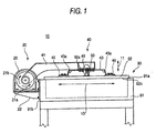
- the cover activating device 10 of the embodiment comprises: a shaft unit 20 which is supported by a vacuum chamber (container) 90 for producing a semiconductor device and having a case 91 and a cover 92, and which has a rotary shaft 21; an arm unit 40 which is coupled to the cover 92 and the rotary shaft 21; and an actuator 60 which drives the rotary shaft 21.
- a vacuum chamber container
- the cover activating device 10 of the embodiment comprises: a shaft unit 20 which is supported by a vacuum chamber (container) 90 for producing a semiconductor device and having a case 91 and a cover 92, and which has a rotary shaft 21; an arm unit 40 which is coupled to the cover 92 and the rotary shaft 21; and an actuator 60 which drives the rotary shaft 21.
- an O-ring which is not shown, and which serves as a sealing member to be in contact with the cover 92 is disposed on an opening face 91a.
- the O-ring of the case 91 has a thickness of 1 mm when the O-ring is not in contact with the cover 92.
- the cover 92 has a plate 92a on the side opposite to the case 91.
- the shaft unit 20 comprises: a base 22 which is fixed to one of four side faces of the case 91 or a side face 91b; a bearing unit 23 which rotatably supports the rotary shaft 21; a bearing bracket 24 through which the bearing unit 23 is fixed to the base 22; and an actuator bracket 25 through which the actuator 60 is fixed to the base 22.
- the arm unit 40 comprises: arms 41, 42 which are fixed to the rotary shaft 21; plate springs 43, 44 which are fixed respectively to the arms 41, 42; spring seat plates 45, 46 which are fixed to the plate spring 43, and also to the cover 92; spring seat plates 47, 48 which are fixed to the plate spring 44, and also to the cover 92; a block 49 which is fixed to the arm 41; and a sensor 50 which is fixed to the block 49 to measure a gap 50a (see Fig. 3) between the block 49 and the plate 92a.
- the plate spring 43 is made of, for example, a metal material, and, when the cover 92 is closed, has a bending angle 43a of 105°.
- the spring constants in the thickness direction of the cover 92 indicated by the arrow 11, in the direction along which the rotary shaft 21 elongates, and which is indicated by the arrow 12, and in the direction which is substantially perpendicular to the directions of the arrows 11 and 12, and which is indicated by the arrow 13 are 74 N/mm, 336 N/mm, and 900 N/mm, respectively.
- the plate spring 44 is configured in the same manner as the lead spring 43.
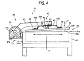
- the shaft unit 20 further comprises a stopper 26 which is to be in contact with the arm 41, thereby preventing an angle 90a (see Fig. 4) formed by the opening face 91a of the case 91 and a face 92b of the cover 92 which is in contact with the O-ring of the case 91, from becoming larger than 105°.
- the actuator 60 comprises: a motor 61 having an output portion 61a serving as a first output portion from which power is output; a first reducer 62 having an input portion 62a serving as a first input portion which receives the power from the output portion 61a of the motor 61, and an output portion 62b serving as a second output portion from which power is output, the first reducer reducing the output of the motor 61 at a reduction ratio of 1/57; and a second reducer 63 having an input portion 63a serving as a second input portion which receives the power from the output portion 62b of the first reducer 62, and an output portion 63b serving as a third output portion from which power is output to the rotary shaft 21 (see Fig.
- the second reducer reducing the output of the first reducer 62 at a reduction ratio of 1/141.
- the first reducer 62 and the second reducer 63 transmit the output of the motor 61 to the rotary shaft 21 with reducing the output at a reduction ratio of 1/8,037.
- the first reducer 62 is a two-stage reducer having: a spur gear 62c which is a first stage reduction mechanism, and which constitutes the input portion 62a; and a differential gear reduction mechanism 62d which is a second stage reduction mechanism.
- the spur gear 62c which meshes with a gear disposed in the output portion 61a of the motor 61 reduces the speed of transmits the output of the motor 61 at a reduction ratio which is equal to or larger than 1/5 and smaller than 1/1, or transmits the output at a ratio of 1/1.
- the second reducer 63 is a two-stage reducer having: a spur gear 63c which is a first stage reduction mechanism, and which constitutes the input portion 63a; and a differential gear reduction mechanism 63d which is a second stage reduction mechanism.
- the spur gear 63c which meshes with a gear disposed in the output portion 62b of the first reducer 62 reduces the speed of the output of the first reducer 62 at a reduction ratio which is equal to or larger than 1/5 and smaller than 1/1, or transmits the output at a ratio of 1/1.
- the reciprocal (hereinafter, referred to as "speed rate") of the reduction ratio of the second reducer 63 is indicated by R 2 .
- the maximum torque which, when the cover 92 is opened, is applied to the output portion 63b of the second reducer 63 is indicated by T L .
- a torque which, when a torque is not applied to the input portion 62a of the first reducer 62, is required for rotating the output portion 62b of the first reducer 62 is indicated by T R1 .
- a torque which, when a torque is not applied to the input portion 63a of the second reducer 63, is required for rotating the output portion 63b of the second reducer 63 is indicated by T R2 .
- a ratio of a torque which is a remainder of a torque applied to the output portion 63b of the second reducer 63 after subjecting to a mechanical loss due to the second reducer 63, to the torque applied to the output portion 63b of the second reducer 63 is indicated by ⁇ 2 .
- the speed rate R 2 is set so as to be larger than a quotient which is obtained by dividing a product of the difference between the maximum value T L and the torque T R2 , and the ratio ⁇ 2 , by the torque T R1 , or so as to satisfy Expression 1 below. [Expression 1] R 2 > ( T L - T R 2 ) ⁇ 2 T R 1
- a torque of 4,606 N ⁇ m which is applied to the output portion 63b of the second reducer 63 when the cover 92 is separated from the O-ring of the case 91 by a small distance as shown in Fig. 4 is the maximum value T L
- the torque T R1 is 33 N ⁇ m
- the torque T R2 is 154 N ⁇ m
- the ratio ⁇ 2 is 0.8
- the cover activating device 10 further comprises a control unit which controls the output of the motor 61, and which is not shown.
- the position of the block 49 with respect to the arm 41 is previously adjusted so that, when the cover 92 is closed by the control unit as shown in Fig. 1, the gap 50a (see Fig. 3) with respect to the plate 92a is 1 mm, and, when the cover 92 is separated from the O-ring of the case 91 by a small distance as shown in Fig. 4, the gap 50a is 3 mm.
- the arms 41, 42 press the cover 92 toward the case 91 via the plate springs 43, 44 and the spring seat plates 45 to 48, and hence the O-ring of the case 91 is compressed by the cover 92.
- the gap 50a (see Fig. 3) between the block 49 and the plate 92a is 1 mm, and the bending angle 43a of the plate spring 43 and the bending angle of the plate spring 44 are 105°.
- the control unit drives the motor 61 so that the rotary shaft 21 is rotated by the actuator 60 in the direction indicated by the arrow 21a.
- the control unit controls the actuator 60 so as to rotate the rotary shaft 21 at a constant acceleration in the direction of the arrow 21a so that the rotational speed of the rotary shaft 21 is changed from 0 deg/sec to 0.13 deg/sec in 0.13 sec, then rotate the rotary shaft 21 at 0.13 deg/sec for 12.18 sec in the direction of the arrow 21a, and further rotate the rotary shaft 21 at a constant deceleration in the direction of the arrow 21a so that the rotational speed of the rotary shaft 21 is changed from 0.13 deg/sec to 0 deg/sec in 0.13 sec.
- the cover 92 which is coupled to the rotary shaft 21 via the spring seat plates 45 to 48, the plate springs 43, 44, and the arms 41, 42 is released from the state of adhering with the O-ring of the case 91, to be separated from the O-ring of the case 91.
- the arms 41, 42 pull the plate springs 43, 44 in the direction opposite to the cover 92, and hence the bending angle 43a of the plate spring 43 and the bending angle of the plate spring 44 are larger than 105°, and the gap 50a (see Fig. 3) between the block 49 and the plate 92a is larger than 1 mm.
- control unit controls the actuator 60 so as to stop for 2 sec, and then drives the motor 61 so that the rotary shaft 21 is again rotated by the actuator 60 in the direction of the arrow 21a.
- control unit controls the actuator 60 so as to rotate the rotary shaft 21 at a constant acceleration in the direction of the arrow 21a so that the rotational speed of the rotary shaft 21 is changed from 0 deg/sec to 1.059 deg/sec in 1.06 sec, then rotate the rotary shaft 21 at 1.059 deg/sec for 87.705 sec in the direction of the arrow 21a, and further rotate the rotary shaft 21 at a constant deceleration in the direction of the arrow 21a so that the rotational speed of the rotary shaft 21 is changed from 1.059 deg/sec to 0 deg/sec in 1.06 sec.
- the rotary shaft 21 is rotated in total by about 95.6° in the direction of the arrow 21a as a result of the series of above-described operations.
- the plate springs 43, 44 are deformed, and hence the angle 90a (see Fig. 4) formed by the opening face 91a of the case 91 and the face 92b of the cover 92 is not 95.6° but 95°.
- the control unit drives the motor 61 so that the rotary shaft 21 is rotated by the actuator 60 in the direction indicated by the arrow 21b.
- control unit controls the actuator 60 so as to rotate the rotary shaft 21 at a constant acceleration in the direction of the arrow 21b so that the rotational speed of the rotary shaft 21 is changed from 0 deg/sec to 1.059 deg/sec in 1.06 sec, then rotate the rotary shaft 21 at 1.059 deg/sec for 87.705 sec in the direction of the arrow 21b, and further rotate the rotary shaft 21 at a constant deceleration in the direction of the arrow 21a so that the rotational speed of the rotary shaft 21 is changed from 1.059 deg/sec to 0 deg/sec in 1.06 sec.
- the control unit controls the actuator 60 so as to stop for 2 sec, and then drives the motor 61 so that the rotary shaft 21 is again rotated by the actuator 60 in the direction of the arrow 21b.
- the control unit controls the actuator 60 so as to rotate the rotary shaft 21 at a constant acceleration in the direction of the arrow 21b so that the rotational speed of the rotary shaft 21 is changed from 0 deg/sec to 0.13 deg/sec in 0.13 sec, then rotate the rotary shaft 21 at 0.13 deg/sec for 12.18 sec in the direction of the arrow 21b, and further rotate the rotary shaft 21 at a constant deceleration in the direction of the arrow 21b so that the rotational speed of the rotary shaft 21 is changed from 0.13 deg/sec to 0 deg/sec in 0.13 sec.
- the cover 92 which is coupled to the rotary shaft 21 via the spring seat plates 45 to 48, the plate springs 43, 44, and the arms 41, 42 is in contact with the O-ring of the case 91 in the state where the cover compresses the O-ring of the case 91.
- the rotary shaft 21 is rotated in total by about 95.6° in the direction of the arrow 21b as a result of the series of above-described operations.
- the plate springs 43, 44 are deformed, and hence the angle 90a (see Fig. 4) formed by the opening face 91a of the case 91 and the face 92b of the cover 92 which is in contact with the O-ring of the case 91 is not -0.6° but 0°.
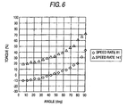
- the speed rate R 2 the angle 90a (see Fig. 4) formed by the opening face 91a of the case 91 and the face 92b of the cover 92, and a ratio of the torque of the motor 61 required for closing the cover 92 to the rated torque of the motor 61 have relationships shown in Fig. 6.
- the speed rate R 2 is 81 which is smaller than 107.9 indicated by Expression 2
- the angle 90a is larger than about 45°
- the torque of the motor 61 is required for closing the cover 92, and hence the cover activating device 10 can suppress closing of the cover 92 due to its own weight.
- the apparatus can be made smaller in size than a conventional apparatus.
- the reduction ratio of the first reducer 62 or the second reducer 63 can be controlled simply by adjusting the reduction ratio of the spur gear 62c or the spur gear 63c which is the first stage reduction mechanism. Therefore, the reduction ratio of the first reducer 62 or the second reducer 63 can be easily controlled as compared with the case where the reduction ratio of the first reducer 62 or the second reducer 63 can be controlled only after the reduction ratio of the differential gear reduction mechanism 62d or the differential gear reduction mechanism 63d is adjusted.
- the plate springs 43, 44 enable the cover 92 to be moved in the thickness direction of the cover 92 indicated by the arrow 11.
- the cover 92 can make contact with the O-ring of the case 91 without causing a shock, and closely adhere at a uniform pressure with the O-ring of the case 91.
- steps of positioning and adjusting them with using actual components can be omitted, and the durability of the O-ring of the case 91 can be maintained.
- the spring constants of the plate springs 43, 44 in the directions of the arrows 11, 12, 13 are 74 N/mm, 336 N/mm, and 900 N/mm, respectively; or the spring constants in the directions of the arrows 12, 13 are larger than the spring constant in the direction of the arrow 11. Therefore, swinging of the cover 92 in the directions of the arrows 12, 13 can be suppressed while enabling the cover 92 to be moved in the direction of the arrow 11.
- the cover activating device 10 when the cover 92 is closed, the bending angle 43a of the plate spring 43 and the bending angle of the plate spring 44 are 105° or not an acute angle, and, during the process of opening or closing the cover 92, the bending angle 43a of the plate spring 43 and the bending angle of the plate spring 44 are not formed as an acute angle. Therefore, repeated fatigue of the plate springs 43, 44 due to opening and closing of the cover 92 is hardly caused as compared with the case where, during the process of opening or closing the cover 92, the bending angle 43a of the plate spring 43 and the bending angle of the plate spring 44 are formed as an acute angle.
- the cover activating device 10 when the cover 92 is closed, the bending angle 43a of the plate spring 43 and the bending angle of the plate spring 44 are not formed as an acute angle, and, when no load is applied to the plate springs 43, 44, the bending angle 43a of the plate spring 43 and the bending angle of the plate spring 44 are not formed as an acute angle. Therefore, the plate springs 43, 44 can be easily shaped as compared with the case where, when no load is applied to the plate springs 43, 44, the bending angle 43a of the plate spring 43 and the bending angle of the plate spring 44 are formed as an acute angle.
- the plate springs 43, 44 are fixed to the cover 92 via the spring seat plates 45 to 48.
- the plate springs 43, 44 may be fixed directly to the cover 92.
- each of the plate springs 43, 44 is formed by a single elastic member.
- each of the plate springs 43, 44 may be formed by plural elastic members.
- the gap 50a (see Fig. 3) between the plate 92a fixed to the cover 92 and the block 49 is measured by the sensor 50.
- the gap between the cover 92 and the block 49 may be measured by the sensor 50.
- the cover activating device 10 is fixed to the side face 91b which is one of the four side faces of the case 91. Therefore, a loading and unloading port for a product such as a liquid crystal display device may be formed in one of the four side faces of the case 91 other than the side face 91b.
- the cover activating device 10 is configured so as to open and close the cover 92 of the vacuum chamber 90 for producing a semiconductor device.
- the apparatus may be configured so as to open and close a cover of a container other than the vacuum chamber 90.
- the activating device for a cover according to the invention attains an effect that it can be made smaller in size than a conventional apparatus, and is useful as, for example, an activating device for a cover of a vacuum chamber for producing a semiconductor device.
Landscapes
- Engineering & Computer Science (AREA)
- General Engineering & Computer Science (AREA)
- Mechanical Engineering (AREA)
- Connection Of Motors, Electrical Generators, Mechanical Devices, And The Like (AREA)
- Container, Conveyance, Adherence, Positioning, Of Wafer (AREA)
- Toilet Supplies (AREA)
- Gear Transmission (AREA)
- Retarders (AREA)
- Pressure Vessels And Lids Thereof (AREA)
- Electrically Driven Valve-Operating Means (AREA)
- Power-Operated Mechanisms For Wings (AREA)
Applications Claiming Priority (2)
| Application Number | Priority Date | Filing Date | Title |
|---|---|---|---|
| JP2003277497A JP2005042816A (ja) | 2003-07-22 | 2003-07-22 | 蓋開閉装置 |
| JP2003277497 | 2003-07-22 |
Publications (3)
| Publication Number | Publication Date |
|---|---|
| EP1500851A2 true EP1500851A2 (fr) | 2005-01-26 |
| EP1500851A3 EP1500851A3 (fr) | 2010-08-04 |
| EP1500851B1 EP1500851B1 (fr) | 2012-09-05 |
Family
ID=33487678
Family Applications (1)
| Application Number | Title | Priority Date | Filing Date |
|---|---|---|---|
| EP04017389A Expired - Lifetime EP1500851B1 (fr) | 2003-07-22 | 2004-07-22 | Appareil pour ouvrir et fermer un couvercle |
Country Status (6)
| Country | Link |
|---|---|
| US (2) | US7213481B2 (fr) |
| EP (1) | EP1500851B1 (fr) |
| JP (1) | JP2005042816A (fr) |
| KR (1) | KR20050012166A (fr) |
| CN (2) | CN100365320C (fr) |
| TW (1) | TWI315375B (fr) |
Cited By (2)
| Publication number | Priority date | Publication date | Assignee | Title |
|---|---|---|---|---|
| WO2014056310A1 (fr) * | 2012-10-10 | 2014-04-17 | Ding Renshi | Récipient sensible au rayonnement infrarouge comportant un couvercle à ouverture et fermeture automatique |
| WO2023099690A1 (fr) * | 2021-12-03 | 2023-06-08 | Getinge Life Science France | Porte de cellule scellée motorisée pour système de connexion à double porte |
Families Citing this family (12)
| Publication number | Priority date | Publication date | Assignee | Title |
|---|---|---|---|---|
| KR100740451B1 (ko) | 2005-10-17 | 2007-07-18 | 주식회사 에이디피엔지니어링 | 진공처리장치 |
| JP4556890B2 (ja) * | 2005-05-16 | 2010-10-06 | パナソニック株式会社 | 画像形成装置 |
| JP5060969B2 (ja) * | 2008-01-15 | 2012-10-31 | 住友重機械工業株式会社 | ロボットの関節駆動装置 |
| JP5359320B2 (ja) * | 2009-01-29 | 2013-12-04 | 株式会社ジェイテクト | 工作機械 |
| JP5533194B2 (ja) * | 2010-04-23 | 2014-06-25 | 株式会社ジェイテクト | 変速歯車装置 |
| KR101124022B1 (ko) * | 2011-05-13 | 2012-03-23 | (주)엠제이티 | 자동개폐장치가 구비된 에칭액 저장용기 |
| USD682902S1 (en) | 2011-08-29 | 2013-05-21 | Nabtesco Corporation | Reduction gear |
| WO2013136842A1 (fr) * | 2012-03-16 | 2013-09-19 | 住友重機械工業株式会社 | Procédé d'entraînement et dispositif de braquage pour un corps rotatif lourd |
| US9394731B2 (en) * | 2013-10-03 | 2016-07-19 | Vac-Tron Equipment, Llc | Door lock system for debris tank |
| CN104616642B (zh) * | 2015-01-06 | 2017-09-15 | 云南格律乐器制造有限公司 | 一种能自动调平的手风琴音孔盖 |
| DE102015014087B4 (de) * | 2015-11-03 | 2017-11-09 | Sew-Eurodrive Gmbh & Co Kg | Getriebe |
| US11268301B2 (en) * | 2017-04-27 | 2022-03-08 | Reinhard Matye | Automatic hatch for bulk material containers |
Citations (5)
| Publication number | Priority date | Publication date | Assignee | Title |
|---|---|---|---|---|
| US2884159A (en) | 1956-01-20 | 1959-04-28 | Owens Corning Fiberglass Corp | Closure operating device |
| JPS63243597A (ja) | 1987-03-30 | 1988-10-11 | Tokyo Electric Power Co Inc:The | オ−プンラツク式気化器の直交レ−ル間に移動可能な自動清掃装置 |
| EP1036954A2 (fr) | 1999-03-16 | 2000-09-20 | Sumitomo Heavy Industries, Ltd. | Réducteur planétaire à excentriques et engrenage planétaire à friction |
| JP2001021039A (ja) | 1999-07-07 | 2001-01-26 | Hitachi Kokusai Electric Inc | 半導体製造装置 |
| JP2001304414A (ja) | 2000-04-25 | 2001-10-31 | Sumitomo Heavy Ind Ltd | 蓋体の開閉駆動装置 |
Family Cites Families (12)
| Publication number | Priority date | Publication date | Assignee | Title |
|---|---|---|---|---|
| AT380222B (de) * | 1984-06-01 | 1986-04-25 | Philips Nv | Korkenzieher |
| CA1244855A (fr) * | 1985-01-18 | 1988-11-15 | Kazuyuki Matsumoto | Organe moteur pour bras manipulateur sur robot |
| US4625888A (en) * | 1985-11-18 | 1986-12-02 | Thompson Andy L | Ground actuated lid operating system |
| WO1988006688A1 (fr) * | 1987-02-27 | 1988-09-07 | Sumitomo Heavy Industries, Ltd. | Reducteur epicycloidal |
| JP2542510B2 (ja) * | 1987-03-27 | 1996-10-09 | 住友重機械工業株式会社 | 遊星歯車機構を有する増減速機 |
| JP3357143B2 (ja) * | 1993-09-30 | 2002-12-16 | ファナック株式会社 | ロボットの負荷をモニタするロボット制御装置 |
| SE505993C2 (sv) * | 1994-06-29 | 1997-10-27 | Volvo Ab | Drivaggregat för ett motorfordon |
| US6029532A (en) * | 1997-01-31 | 2000-02-29 | Reliance Electric Industrial Company | Gearing commonality system for gear reducers |
| JP4349688B2 (ja) * | 1999-06-23 | 2009-10-21 | 日産自動車株式会社 | 車両の駆動装置 |
| IT1317174B1 (it) * | 2000-04-06 | 2003-05-27 | Giacomini Spa | Attuatore perfezionato per impianti di riscaldamento/raffrescamento ad acqua e sanitari |
| JP4636651B2 (ja) * | 2000-04-07 | 2011-02-23 | Gknドライブラインジャパン株式会社 | 動力伝達装置 |
| US6796921B1 (en) * | 2003-05-30 | 2004-09-28 | One World Technologies Limited | Three speed rotary power tool |
-
2003
- 2003-07-22 JP JP2003277497A patent/JP2005042816A/ja active Pending
-
2004
- 2004-07-22 KR KR1020040057378A patent/KR20050012166A/ko not_active Ceased
- 2004-07-22 CN CNB2004100544596A patent/CN100365320C/zh not_active Expired - Fee Related
- 2004-07-22 CN CNB200710196463XA patent/CN100570180C/zh not_active Expired - Lifetime
- 2004-07-22 TW TW093121909A patent/TWI315375B/zh not_active IP Right Cessation
- 2004-07-22 EP EP04017389A patent/EP1500851B1/fr not_active Expired - Lifetime
- 2004-07-22 US US10/896,661 patent/US7213481B2/en not_active Expired - Fee Related
-
2007
- 2007-04-09 US US11/697,820 patent/US7381145B2/en not_active Expired - Lifetime
Patent Citations (5)
| Publication number | Priority date | Publication date | Assignee | Title |
|---|---|---|---|---|
| US2884159A (en) | 1956-01-20 | 1959-04-28 | Owens Corning Fiberglass Corp | Closure operating device |
| JPS63243597A (ja) | 1987-03-30 | 1988-10-11 | Tokyo Electric Power Co Inc:The | オ−プンラツク式気化器の直交レ−ル間に移動可能な自動清掃装置 |
| EP1036954A2 (fr) | 1999-03-16 | 2000-09-20 | Sumitomo Heavy Industries, Ltd. | Réducteur planétaire à excentriques et engrenage planétaire à friction |
| JP2001021039A (ja) | 1999-07-07 | 2001-01-26 | Hitachi Kokusai Electric Inc | 半導体製造装置 |
| JP2001304414A (ja) | 2000-04-25 | 2001-10-31 | Sumitomo Heavy Ind Ltd | 蓋体の開閉駆動装置 |
Cited By (5)
| Publication number | Priority date | Publication date | Assignee | Title |
|---|---|---|---|---|
| WO2014056310A1 (fr) * | 2012-10-10 | 2014-04-17 | Ding Renshi | Récipient sensible au rayonnement infrarouge comportant un couvercle à ouverture et fermeture automatique |
| WO2023099690A1 (fr) * | 2021-12-03 | 2023-06-08 | Getinge Life Science France | Porte de cellule scellée motorisée pour système de connexion à double porte |
| FR3130007A1 (fr) * | 2021-12-03 | 2023-06-09 | Getinge Life Science France | Porte de cellule étanche motorisée pour système de connexion à double porte |
| US20250020016A1 (en) * | 2021-12-03 | 2025-01-16 | Getinge Life Science France | Motorised sealed cell door for double door connection system |
| US12577822B2 (en) * | 2021-12-03 | 2026-03-17 | Getinge Life Science France | Motorised sealed cell door for double door connection system |
Also Published As
| Publication number | Publication date |
|---|---|
| US20050016321A1 (en) | 2005-01-27 |
| EP1500851B1 (fr) | 2012-09-05 |
| US7213481B2 (en) | 2007-05-08 |
| KR20050012166A (ko) | 2005-01-31 |
| CN1576661A (zh) | 2005-02-09 |
| CN101173712A (zh) | 2008-05-07 |
| TW200508526A (en) | 2005-03-01 |
| JP2005042816A (ja) | 2005-02-17 |
| US20070179005A1 (en) | 2007-08-02 |
| CN100570180C (zh) | 2009-12-16 |
| US7381145B2 (en) | 2008-06-03 |
| EP1500851A3 (fr) | 2010-08-04 |
| CN100365320C (zh) | 2008-01-30 |
| TWI315375B (en) | 2009-10-01 |
Similar Documents
| Publication | Publication Date | Title |
|---|---|---|
| US7381145B2 (en) | Apparatus for opening and closing cover | |
| JP4268881B2 (ja) | 車両テールゲート用のリフト補助機構 | |
| US6217094B1 (en) | Object holding device | |
| JPS5974092A (ja) | ゲ−ト開閉装置 | |
| CN1471287A (zh) | 用于便携装置的折盖驱动装置 | |
| JP2011137537A (ja) | 真空用ゲートバルブ | |
| KR101149481B1 (ko) | 커버 작동장치 | |
| JP2006317009A (ja) | アクチュエータ及び蓋開閉装置 | |
| WO2004046526A1 (fr) | Dispositif papillon | |
| CN210102127U (zh) | 一种卸料装置 | |
| JP3750934B2 (ja) | 吸気絞弁装置 | |
| US20230407692A1 (en) | Powered vehicle closure system having non-linear torsion bar | |
| JP4654370B1 (ja) | 真空用ゲートバルブ | |
| JPH0916095A (ja) | 電動開閉装置 | |
| CA2311054A1 (fr) | Ferme-porte equilibre | |
| CN218344537U (zh) | 氧化铝收集斗用卸料阀 | |
| JPH06148362A (ja) | 情報処理装置 | |
| JPH0639380Y2 (ja) | 硬貨処理機の送りベルト駆動装置 | |
| JPS5965685A (ja) | 弁体の駆動装置 | |
| JPH0115980Y2 (fr) | ||
| JPH04321493A (ja) | 回転駆動機構 | |
| CA2441091C (fr) | Mecanisme d'aide au levage pour hayons de vehicules | |
| JPH11354610A (ja) | 基板搬送装置および基板搬送方法 | |
| JPH11233393A (ja) | 半導体処理装置 | |
| JP2004208095A (ja) | モニター開閉装置 |
Legal Events
| Date | Code | Title | Description |
|---|---|---|---|
| PUAI | Public reference made under article 153(3) epc to a published international application that has entered the european phase |
Free format text: ORIGINAL CODE: 0009012 |
|
| AK | Designated contracting states |
Kind code of ref document: A2 Designated state(s): AT BE BG CH CY CZ DE DK EE ES FI FR GB GR HU IE IT LI LU MC NL PL PT RO SE SI SK TR |
|
| AX | Request for extension of the european patent |
Extension state: AL HR LT LV MK |
|
| PUAL | Search report despatched |
Free format text: ORIGINAL CODE: 0009013 |
|
| AK | Designated contracting states |
Kind code of ref document: A3 Designated state(s): AT BE BG CH CY CZ DE DK EE ES FI FR GB GR HU IE IT LI LU MC NL PL PT RO SE SI SK TR |
|
| AX | Request for extension of the european patent |
Extension state: AL HR LT LV MK |
|
| RIC1 | Information provided on ipc code assigned before grant |
Ipc: F16J 13/00 20060101AFI20040928BHEP Ipc: B65D 90/10 20060101ALI20100630BHEP Ipc: F16H 1/32 20060101ALI20100630BHEP |
|
| 17P | Request for examination filed |
Effective date: 20110204 |
|
| AKX | Designation fees paid |
Designated state(s): AT BE BG CH CY CZ DE DK EE ES FI FR GB GR HU IE IT LI LU MC NL PL PT RO SE SI SK TR |
|
| 17Q | First examination report despatched |
Effective date: 20111104 |
|
| GRAP | Despatch of communication of intention to grant a patent |
Free format text: ORIGINAL CODE: EPIDOSNIGR1 |
|
| GRAS | Grant fee paid |
Free format text: ORIGINAL CODE: EPIDOSNIGR3 |
|
| GRAA | (expected) grant |
Free format text: ORIGINAL CODE: 0009210 |
|
| AK | Designated contracting states |
Kind code of ref document: B1 Designated state(s): AT BE BG CH CY CZ DE DK EE ES FI FR GB GR HU IE IT LI LU MC NL PL PT RO SE SI SK TR |
|
| REG | Reference to a national code |
Ref country code: GB Ref legal event code: FG4D |
|
| REG | Reference to a national code |
Ref country code: CH Ref legal event code: EP |
|
| REG | Reference to a national code |
Ref country code: AT Ref legal event code: REF Ref document number: 574285 Country of ref document: AT Kind code of ref document: T Effective date: 20120915 |
|
| REG | Reference to a national code |
Ref country code: IE Ref legal event code: FG4D |
|
| REG | Reference to a national code |
Ref country code: DE Ref legal event code: R096 Ref document number: 602004039190 Country of ref document: DE Effective date: 20121031 |
|
| REG | Reference to a national code |
Ref country code: AT Ref legal event code: MK05 Ref document number: 574285 Country of ref document: AT Kind code of ref document: T Effective date: 20120905 |
|
| REG | Reference to a national code |
Ref country code: NL Ref legal event code: VDEP Effective date: 20120905 |
|
| PG25 | Lapsed in a contracting state [announced via postgrant information from national office to epo] |
Ref country code: FI Free format text: LAPSE BECAUSE OF FAILURE TO SUBMIT A TRANSLATION OF THE DESCRIPTION OR TO PAY THE FEE WITHIN THE PRESCRIBED TIME-LIMIT Effective date: 20120905 Ref country code: AT Free format text: LAPSE BECAUSE OF FAILURE TO SUBMIT A TRANSLATION OF THE DESCRIPTION OR TO PAY THE FEE WITHIN THE PRESCRIBED TIME-LIMIT Effective date: 20120905 Ref country code: CY Free format text: LAPSE BECAUSE OF FAILURE TO SUBMIT A TRANSLATION OF THE DESCRIPTION OR TO PAY THE FEE WITHIN THE PRESCRIBED TIME-LIMIT Effective date: 20120905 |
|
| PG25 | Lapsed in a contracting state [announced via postgrant information from national office to epo] |
Ref country code: SE Free format text: LAPSE BECAUSE OF FAILURE TO SUBMIT A TRANSLATION OF THE DESCRIPTION OR TO PAY THE FEE WITHIN THE PRESCRIBED TIME-LIMIT Effective date: 20120905 Ref country code: SI Free format text: LAPSE BECAUSE OF FAILURE TO SUBMIT A TRANSLATION OF THE DESCRIPTION OR TO PAY THE FEE WITHIN THE PRESCRIBED TIME-LIMIT Effective date: 20120905 Ref country code: GR Free format text: LAPSE BECAUSE OF FAILURE TO SUBMIT A TRANSLATION OF THE DESCRIPTION OR TO PAY THE FEE WITHIN THE PRESCRIBED TIME-LIMIT Effective date: 20121206 |
|
| PG25 | Lapsed in a contracting state [announced via postgrant information from national office to epo] |
Ref country code: ES Free format text: LAPSE BECAUSE OF FAILURE TO SUBMIT A TRANSLATION OF THE DESCRIPTION OR TO PAY THE FEE WITHIN THE PRESCRIBED TIME-LIMIT Effective date: 20121216 Ref country code: CZ Free format text: LAPSE BECAUSE OF FAILURE TO SUBMIT A TRANSLATION OF THE DESCRIPTION OR TO PAY THE FEE WITHIN THE PRESCRIBED TIME-LIMIT Effective date: 20120905 Ref country code: BE Free format text: LAPSE BECAUSE OF FAILURE TO SUBMIT A TRANSLATION OF THE DESCRIPTION OR TO PAY THE FEE WITHIN THE PRESCRIBED TIME-LIMIT Effective date: 20120905 Ref country code: EE Free format text: LAPSE BECAUSE OF FAILURE TO SUBMIT A TRANSLATION OF THE DESCRIPTION OR TO PAY THE FEE WITHIN THE PRESCRIBED TIME-LIMIT Effective date: 20120905 Ref country code: NL Free format text: LAPSE BECAUSE OF FAILURE TO SUBMIT A TRANSLATION OF THE DESCRIPTION OR TO PAY THE FEE WITHIN THE PRESCRIBED TIME-LIMIT Effective date: 20120905 Ref country code: RO Free format text: LAPSE BECAUSE OF FAILURE TO SUBMIT A TRANSLATION OF THE DESCRIPTION OR TO PAY THE FEE WITHIN THE PRESCRIBED TIME-LIMIT Effective date: 20120905 |
|
| PG25 | Lapsed in a contracting state [announced via postgrant information from national office to epo] |
Ref country code: SK Free format text: LAPSE BECAUSE OF FAILURE TO SUBMIT A TRANSLATION OF THE DESCRIPTION OR TO PAY THE FEE WITHIN THE PRESCRIBED TIME-LIMIT Effective date: 20120905 Ref country code: PL Free format text: LAPSE BECAUSE OF FAILURE TO SUBMIT A TRANSLATION OF THE DESCRIPTION OR TO PAY THE FEE WITHIN THE PRESCRIBED TIME-LIMIT Effective date: 20120905 Ref country code: PT Free format text: LAPSE BECAUSE OF FAILURE TO SUBMIT A TRANSLATION OF THE DESCRIPTION OR TO PAY THE FEE WITHIN THE PRESCRIBED TIME-LIMIT Effective date: 20130107 |
|
| PLBE | No opposition filed within time limit |
Free format text: ORIGINAL CODE: 0009261 |
|
| STAA | Information on the status of an ep patent application or granted ep patent |
Free format text: STATUS: NO OPPOSITION FILED WITHIN TIME LIMIT |
|
| PG25 | Lapsed in a contracting state [announced via postgrant information from national office to epo] |
Ref country code: BG Free format text: LAPSE BECAUSE OF FAILURE TO SUBMIT A TRANSLATION OF THE DESCRIPTION OR TO PAY THE FEE WITHIN THE PRESCRIBED TIME-LIMIT Effective date: 20121205 Ref country code: DK Free format text: LAPSE BECAUSE OF FAILURE TO SUBMIT A TRANSLATION OF THE DESCRIPTION OR TO PAY THE FEE WITHIN THE PRESCRIBED TIME-LIMIT Effective date: 20120905 |
|
| 26N | No opposition filed |
Effective date: 20130606 |
|
| PG25 | Lapsed in a contracting state [announced via postgrant information from national office to epo] |
Ref country code: IT Free format text: LAPSE BECAUSE OF FAILURE TO SUBMIT A TRANSLATION OF THE DESCRIPTION OR TO PAY THE FEE WITHIN THE PRESCRIBED TIME-LIMIT Effective date: 20120905 |
|
| REG | Reference to a national code |
Ref country code: DE Ref legal event code: R097 Ref document number: 602004039190 Country of ref document: DE Effective date: 20130606 |
|
| PG25 | Lapsed in a contracting state [announced via postgrant information from national office to epo] |
Ref country code: MC Free format text: LAPSE BECAUSE OF FAILURE TO SUBMIT A TRANSLATION OF THE DESCRIPTION OR TO PAY THE FEE WITHIN THE PRESCRIBED TIME-LIMIT Effective date: 20120905 |
|
| REG | Reference to a national code |
Ref country code: CH Ref legal event code: PL |
|
| GBPC | Gb: european patent ceased through non-payment of renewal fee |
Effective date: 20130722 |
|
| REG | Reference to a national code |
Ref country code: IE Ref legal event code: MM4A |
|
| REG | Reference to a national code |
Ref country code: FR Ref legal event code: ST Effective date: 20140331 |
|
| PG25 | Lapsed in a contracting state [announced via postgrant information from national office to epo] |
Ref country code: GB Free format text: LAPSE BECAUSE OF NON-PAYMENT OF DUE FEES Effective date: 20130722 Ref country code: LI Free format text: LAPSE BECAUSE OF NON-PAYMENT OF DUE FEES Effective date: 20130731 Ref country code: CH Free format text: LAPSE BECAUSE OF NON-PAYMENT OF DUE FEES Effective date: 20130731 |
|
| PG25 | Lapsed in a contracting state [announced via postgrant information from national office to epo] |
Ref country code: FR Free format text: LAPSE BECAUSE OF NON-PAYMENT OF DUE FEES Effective date: 20130731 |
|
| PG25 | Lapsed in a contracting state [announced via postgrant information from national office to epo] |
Ref country code: IE Free format text: LAPSE BECAUSE OF NON-PAYMENT OF DUE FEES Effective date: 20130722 |
|
| PG25 | Lapsed in a contracting state [announced via postgrant information from national office to epo] |
Ref country code: TR Free format text: LAPSE BECAUSE OF FAILURE TO SUBMIT A TRANSLATION OF THE DESCRIPTION OR TO PAY THE FEE WITHIN THE PRESCRIBED TIME-LIMIT Effective date: 20120905 |
|
| PG25 | Lapsed in a contracting state [announced via postgrant information from national office to epo] |
Ref country code: HU Free format text: LAPSE BECAUSE OF FAILURE TO SUBMIT A TRANSLATION OF THE DESCRIPTION OR TO PAY THE FEE WITHIN THE PRESCRIBED TIME-LIMIT; INVALID AB INITIO Effective date: 20040722 Ref country code: LU Free format text: LAPSE BECAUSE OF NON-PAYMENT OF DUE FEES Effective date: 20130722 |
|
| PGFP | Annual fee paid to national office [announced via postgrant information from national office to epo] |
Ref country code: DE Payment date: 20150721 Year of fee payment: 12 |
|
| REG | Reference to a national code |
Ref country code: DE Ref legal event code: R119 Ref document number: 602004039190 Country of ref document: DE |
|
| PG25 | Lapsed in a contracting state [announced via postgrant information from national office to epo] |
Ref country code: DE Free format text: LAPSE BECAUSE OF NON-PAYMENT OF DUE FEES Effective date: 20170201 |