EP1500854A1 - Ventil für einen Gaszylinder mit einer Einrichtung gegen die adiabatische Kompression - Google Patents
Ventil für einen Gaszylinder mit einer Einrichtung gegen die adiabatische Kompression Download PDFInfo
- Publication number
- EP1500854A1 EP1500854A1 EP03077331A EP03077331A EP1500854A1 EP 1500854 A1 EP1500854 A1 EP 1500854A1 EP 03077331 A EP03077331 A EP 03077331A EP 03077331 A EP03077331 A EP 03077331A EP 1500854 A1 EP1500854 A1 EP 1500854A1
- Authority
- EP
- European Patent Office
- Prior art keywords
- valve
- passage
- seat
- orifice
- gas
- Prior art date
- Legal status (The legal status is an assumption and is not a legal conclusion. Google has not performed a legal analysis and makes no representation as to the accuracy of the status listed.)
- Granted
Links
- 238000007906 compression Methods 0.000 title description 22
- 230000006835 compression Effects 0.000 title description 2
- 230000035939 shock Effects 0.000 claims abstract description 22
- 230000000694 effects Effects 0.000 claims abstract description 6
- 238000004891 communication Methods 0.000 claims description 18
- 238000011144 upstream manufacturing Methods 0.000 claims description 12
- 239000003638 chemical reducing agent Substances 0.000 claims 4
- 239000007789 gas Substances 0.000 description 56
- 239000008188 pellet Substances 0.000 description 5
- 238000007789 sealing Methods 0.000 description 3
- 240000008042 Zea mays Species 0.000 description 2
- QVGXLLKOCUKJST-UHFFFAOYSA-N atomic oxygen Chemical compound [O] QVGXLLKOCUKJST-UHFFFAOYSA-N 0.000 description 2
- 238000012986 modification Methods 0.000 description 2
- 230000004048 modification Effects 0.000 description 2
- 230000001590 oxidative effect Effects 0.000 description 2
- 239000001301 oxygen Substances 0.000 description 2
- 229910052760 oxygen Inorganic materials 0.000 description 2
- 239000002245 particle Substances 0.000 description 2
- 206010040560 shock Diseases 0.000 description 2
- 229920000426 Microplastic Polymers 0.000 description 1
- 230000007423 decrease Effects 0.000 description 1
- 230000001419 dependent effect Effects 0.000 description 1
- 238000005516 engineering process Methods 0.000 description 1
- 238000001595 flow curve Methods 0.000 description 1
- 239000001307 helium Substances 0.000 description 1
- 229910052734 helium Inorganic materials 0.000 description 1
- SWQJXJOGLNCZEY-UHFFFAOYSA-N helium atom Chemical compound [He] SWQJXJOGLNCZEY-UHFFFAOYSA-N 0.000 description 1
- 238000000034 method Methods 0.000 description 1
- 230000007935 neutral effect Effects 0.000 description 1
- 238000002640 oxygen therapy Methods 0.000 description 1
- 229920003023 plastic Polymers 0.000 description 1
- 125000006850 spacer group Chemical group 0.000 description 1
- 210000003462 vein Anatomy 0.000 description 1
Images


Classifications
-
- F—MECHANICAL ENGINEERING; LIGHTING; HEATING; WEAPONS; BLASTING
- F17—STORING OR DISTRIBUTING GASES OR LIQUIDS
- F17C—VESSELS FOR CONTAINING OR STORING COMPRESSED, LIQUEFIED OR SOLIDIFIED GASES; FIXED-CAPACITY GAS-HOLDERS; FILLING VESSELS WITH, OR DISCHARGING FROM VESSELS, COMPRESSED, LIQUEFIED, OR SOLIDIFIED GASES
- F17C13/00—Details of vessels or of the filling or discharging of vessels
- F17C13/04—Arrangement or mounting of valves
-
- F—MECHANICAL ENGINEERING; LIGHTING; HEATING; WEAPONS; BLASTING
- F16—ENGINEERING ELEMENTS AND UNITS; GENERAL MEASURES FOR PRODUCING AND MAINTAINING EFFECTIVE FUNCTIONING OF MACHINES OR INSTALLATIONS; THERMAL INSULATION IN GENERAL
- F16K—VALVES; TAPS; COCKS; ACTUATING-FLOATS; DEVICES FOR VENTING OR AERATING
- F16K1/00—Lift valves or globe valves, i.e. cut-off apparatus with closure members having at least a component of their opening and closing motion perpendicular to the closing faces
- F16K1/30—Lift valves or globe valves, i.e. cut-off apparatus with closure members having at least a component of their opening and closing motion perpendicular to the closing faces specially adapted for pressure containers
- F16K1/304—Shut-off valves with additional means
- F16K1/305—Shut-off valves with additional means with valve member and actuator on the same side of the seat
-
- F—MECHANICAL ENGINEERING; LIGHTING; HEATING; WEAPONS; BLASTING
- F16—ENGINEERING ELEMENTS AND UNITS; GENERAL MEASURES FOR PRODUCING AND MAINTAINING EFFECTIVE FUNCTIONING OF MACHINES OR INSTALLATIONS; THERMAL INSULATION IN GENERAL
- F16K—VALVES; TAPS; COCKS; ACTUATING-FLOATS; DEVICES FOR VENTING OR AERATING
- F16K1/00—Lift valves or globe valves, i.e. cut-off apparatus with closure members having at least a component of their opening and closing motion perpendicular to the closing faces
- F16K1/30—Lift valves or globe valves, i.e. cut-off apparatus with closure members having at least a component of their opening and closing motion perpendicular to the closing faces specially adapted for pressure containers
- F16K1/307—Additional means used in combination with the main valve
-
- F—MECHANICAL ENGINEERING; LIGHTING; HEATING; WEAPONS; BLASTING
- F17—STORING OR DISTRIBUTING GASES OR LIQUIDS
- F17C—VESSELS FOR CONTAINING OR STORING COMPRESSED, LIQUEFIED OR SOLIDIFIED GASES; FIXED-CAPACITY GAS-HOLDERS; FILLING VESSELS WITH, OR DISCHARGING FROM VESSELS, COMPRESSED, LIQUEFIED, OR SOLIDIFIED GASES
- F17C2205/00—Vessel construction, in particular mounting arrangements, attachments or identifications means
- F17C2205/03—Fluid connections, filters, valves, closure means or other attachments
- F17C2205/0302—Fittings, valves, filters, or components in connection with the gas storage device
- F17C2205/0323—Valves
- F17C2205/0329—Valves manually actuated
-
- F—MECHANICAL ENGINEERING; LIGHTING; HEATING; WEAPONS; BLASTING
- F17—STORING OR DISTRIBUTING GASES OR LIQUIDS
- F17C—VESSELS FOR CONTAINING OR STORING COMPRESSED, LIQUEFIED OR SOLIDIFIED GASES; FIXED-CAPACITY GAS-HOLDERS; FILLING VESSELS WITH, OR DISCHARGING FROM VESSELS, COMPRESSED, LIQUEFIED, OR SOLIDIFIED GASES
- F17C2205/00—Vessel construction, in particular mounting arrangements, attachments or identifications means
- F17C2205/03—Fluid connections, filters, valves, closure means or other attachments
- F17C2205/0302—Fittings, valves, filters, or components in connection with the gas storage device
- F17C2205/0382—Constructional details of valves, regulators
-
- F—MECHANICAL ENGINEERING; LIGHTING; HEATING; WEAPONS; BLASTING
- F17—STORING OR DISTRIBUTING GASES OR LIQUIDS
- F17C—VESSELS FOR CONTAINING OR STORING COMPRESSED, LIQUEFIED OR SOLIDIFIED GASES; FIXED-CAPACITY GAS-HOLDERS; FILLING VESSELS WITH, OR DISCHARGING FROM VESSELS, COMPRESSED, LIQUEFIED, OR SOLIDIFIED GASES
- F17C2205/00—Vessel construction, in particular mounting arrangements, attachments or identifications means
- F17C2205/03—Fluid connections, filters, valves, closure means or other attachments
- F17C2205/0302—Fittings, valves, filters, or components in connection with the gas storage device
- F17C2205/0382—Constructional details of valves, regulators
- F17C2205/0385—Constructional details of valves, regulators in blocks or units
Definitions
- the present invention relates to a tap for gas cylinder having a valve body having a gas passage formed in the valve body, a valve open / closed and a regulator attached to the valve body, the valve can be opened to allow the gas to to flow in withdrawal mode through said passage to the regulator, and means for limiting the shock wave in case opening of the valve, this means being disposed between the valve and the regulator.
- the invention therefore aims to remedy this disadvantage and provide a tap for gas cylinder with a means to avoid adiabatic shock without disturbing the gas expansion curve.
- the tap for gas cylinder of the type mentioned above is characterized in that that the means for limiting the shock wave comprises a valve movable disposed in said gas passage, this valve, to the opening of the valve, being forced under the effect of the wave shock, from a first position to a passage surface normal, to a second position, unsealed, surface limited passage in order to reduce the shock wave, said valve taking up its first position passing surface normal after the gas pressure has settled on the two sides of the flap.
- the valve is normally in the position open, that is, the crossing surface position normal, and when the main valve is open the flapper is instantly pushed under the effect of speed and gas pressure to its second position, not waterproof, limiting the area of passage of the gas in order to limit or to absorb the shock wave or the adiabatic shock.
- a small hole having a surface of sufficiently large passage not to impede the flow at low pressure remains open, and after balancing pressures, the valve resumes its position passing surface higher, so that the system according to the invention allows to have a variable pressure loss, unlike the constant loss of load caused by known filters.
- the system according to the invention makes it possible to place the filter in the tail of the valve (inlet or conical connection) having a larger area and so avoid shocks on the filtered.
- the system according to the invention is very interesting for applications that use oxidizing gases, i.e. oxygen, but also has non-negligible benefits for applications with neutral gases or any.
- the system is particularly suitable for oxygen applications greater than 200 bar.
- the invention improves user safety by avoiding dangerous phenomena.
- the system according to the invention is particularly advantageous in oxygen therapy.
- the system is interesting for faucets with integrated piston regulator having a flap in the bass pressure that is normally open but it may apply to other technologies.
- the system can also be used with a regulator having a flapper in the high pressure in normal position closed or open.
- the system according to the invention can be used in a set of a standard faucet or classic with an open / closed valve connected by a pipe to a regulator. In this case the anti-compression system adiabatic would be in the pipeline just in front of the regulator seat (claim 8).
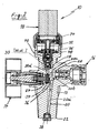
- FIGS 1 and 2 show a tap 10 for gas cylinder according to the present invention comprising a valve body 12, an open / closed main valve 14, a filling valve 16 and an integrated regulator 18.
- a gas passage 20 extends from the lower end 22 of connecting the valve body 12 to the gas cylinder (not shown) to integrated regulator 18. This passage gas 20 is commonly referred to as a high pressure part of the tap 10.
- the gas passage 20 has a first portion 20a extending from the lower end of the valve body 12 obliquely upward and communicating with a first transverse portion 20b which opens into a first cavity transversal 24 which, in turn, is in communication with a second transverse portion 20c of the gas passage 20 which in turn opens into a second cavity 26.
- the passage of gas further includes a vertical part 20d which communicates with the second part transverse 20c and which has a vertical counterbore 28, best shown in FIGS. 3 and 4, and wherein the adiabatic anti-compression system 30 is arranged according to the invention (details X and Z of FIGS. 1 and 2).
- the system adiabatic anti-compression 30 is in bore 28 just below the piston 32 of the regulator 18 which is connected to the upper end of the valve body 12 and which is known in the prior art.
- the main valve 14 is also known in the prior art and therefore will not be described here in detail. Just mention that this main valve 14 is provided with a sealing ring 34 engaging sealing an annular seat 36 at the bottom of the first cavity transversal 24 when the main valve 14 is closed. In opening position of the main valve 14 the ring seal 34 is disengaged from the ring seat 36. Also the filling valve 16 is known in the art previous and therefore will not be described here in detail.
- a filter 38 is at the lower end of the first oblique portion 20a of the gas passage 20.
- the piston 32 of the regulator 18 is provided at its lower end with a plastic pellet 40 which cooperates with an orifice 42 of the seat of the regulator 46, see FIGS. view of the adjustment of the gas pressure.
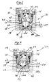
- the adiabatic anti-compression system 30 which will be now described with reference to FIGS. 3 and 4, comprises two pieces 44 and 46 nested one inside the other.
- the first piece 44 that is to say the lower piece, is a valve 44 movable vertically in the counter-bore vertical 28 and the other upper part 46, that is to say the seat 46 of the regulator 18, is received by a Threaded engagement 48 in the counterbore 28.
- a ring 50 is disposed between the fixed seat 46 and the valve body 12.
- the fixed seat 46 is provided with several recesses 50 formed in its upper surface for engaging a clamping tool to secure the seat 46 in the counterbore 28 of the body 12 of the tap.
- a vertical gas passage 54 extends from one end to the other to through the two pieces 44 and 46 of the anti-compression system adiabatic 30.
- This vertical passage 54 has at the end upper seat 46 the fixed orifice 42 cooperating with the pellet 40 of the piston 30 of the regulator 18 for the purpose of setting the pressure of the gas.
- the vertical passage 54 also has a central orifice 56 through the valve 44 axially and placing the front and the downstream of the valve 44 in communication permed. This orifice 56 forms the passage surface limited.
- the movable valve 44 located on the upstream side of the seat fixed 46 is also provided with an annular guide portion vertical 60 extending upwards from the head end lower 58 of the valve 44 and slidably received in a vertical bore 62 of the seat 46 of the regulator 18.
- One or more radial cutouts or openings, by example of the holes, 64 are practiced in the part of vertical guide 60 of the valve 44. These openings 46 extend radially through the wall of the part of guide 60 to open into a bore 66 formed in inside the mobile valve 44.
- the central orifice 56 of the valve 44 is also in communication with the bore 66.
- the bore 66 is in permanent communication with the bore 62 of the seat 46 and the bore 62 is in communication permanent with the orifice 42.
- These radial openings 64 in the first position to normal passage surface of the valve 44, open into the volume of the counterbore 28 surrounding the valve 44 and make part of a passage bypassing the central orifice 56 and extending around the outside of the valve 44 in the counterbore 28 to place the upstream of the valve 44, that is to say the portion 20d of the gas passage 20 in communication with the downstream of the valve 44, that is to say the downstream of the central orifice 56 of the valve 44 of the adiabatic anti-compression system 30.
- a compression spring 68 is provided inside the two pieces 44 and 46 and leans up against a surface bottom of the bore 62 of the seat 46 of the regulator 18 and at the bottom against a bottom surface of the bore 66 of the valve 44 in view of normally pushing the movable flap 44 downwards to his first position in engagement with a surface of bottom 28a of the counterboring 28 of the valve body 12, around of the portion 20d of the gas passage 20 opening into the counterbore 28.
- the head portion 58 of the valve 44 is provided with its upper end of a radial shoulder forming a surface of annular stop 68 capable of contacting an annular surface counter-stop 70 at the lower end of the seat 46 the regulator 18.
- the outside diameter of the head portion 58 of the flapper mobile 44 is smaller than the diameter of the surface surrounding circumferential circumferential circumferential counterbore 28 and the openings 64 are formed in the part of vertical guidance 60 between the radial shoulder 68 and the end upper portion of the guide portion 60.
- the appropriate means such as spacers, ribs or grooves forming at least a radial passage 72, or any other suitable means to ensure that the movable flap 44 can not come into sealing engagement with the bottom surface 28a of the bore 28 of the valve body 12, so that in the position lower (first position) of the valve 44, shown in FIG. FIG. 3, the portion 20d of the gas passage 20 is in communication with the downstream of the valve 44 (downstream of the orifice central 56) by the volume of the counter-bore 28 surrounding the valve 44 and the radial openings 64 (forming the normal passage surface), and also through the central hole 56 forming the limited passage area.
- the appropriate means such as spacers, ribs or grooves forming at least a radial passage 72, or any other suitable means to ensure that the movable flap 44 can not come into sealing engagement with the bottom surface 28a of the bore 28 of the valve body 12, so that in the position lower (first position) of the valve 44, shown in FIG. FIG. 3, the portion 20d of the gas passage 20 is in
- the flap mobile 44 is moved upward so that its surface of annular stop 68 is in contact with the counter-stop surface 70 of the fixed seat 46 of the regulator 18, and the part of guide 60 with its radial openings 64 is received completely inside the bore 62 of the fixed seat 46.
- the openings 64 are thus closed or closed and the gas does not can no longer penetrate the counter-bore 28 through these openings 64 inside the adiabatic anti-compression system 30.
- the high pressure gas can pass through the adiabatic anti-compression system 30 only by the small limited central orifice 56 and adiabatic shock applied to the pellet 40 of the mobile piston 32 of the regulator 10 is limited.
- the adiabatic anti-compression system 30 is located normally in the position of Figure 3 when the main tap 14 is closed. In this case the mobile flap 44 is pushed by the spring 68 downwards and engages the surface 28a of the bottom of the counter-bore 28 of the body 12 of the valve 10 around the portion 20d of the gas passage 20.
- the gas under high pressure arriving at high speed by the part 20d of passage 20 forces the movable flap 44 upwards against the effect of the spring 68 in order to move the valve 44 towards its upper position in which the openings 64 is located inside the fixed seat 46 of the regulator 18 and are therefore more in communication with the volume of the counter-bore 28 surrounding the mobile valve 44.
- the gas under pressure can go through the anti-compression system adiabatic 30 only through the orifice 56 to surface of practical minimum passage in the valve 44 which is in permanent communication with the upstream and downstream of the valve 44.
- the adiabatic anti-compression system 30 limits the flow rate and the speed of the gas in order to protect the expansion valve, by providing a limited flow area for the gas under pressure, and when the pressure of the gas installed on both sides of the valve, the valve is moved to an open position, providing a higher normal passage area (two to five times higher) to the pressurized gas.
- the adiabatic anti-compression system according to the present invention provides a variable gas flow passage area, ie a limited passage area at the opening of the main valve and a higher normal passage area after the gas has settled on both sides of the valve.
- the system according to the invention is a system with variable pressure drop. It should be noted that the resistance to the passage of the pressurized gas through the central orifice 58 is lower than the resistance to the passage of the gas by the filters known from the prior art, and therefore the system of the present invention less relaxation than the known filters, as shown in Figure 5, but provides the same protection against adiabatic shock as the known filters. As shown in FIG. 5, with the system according to the invention, the desired set pressure P 2 can be maintained longer as the pressure P 1 in the bottle decreases and the bottle is almost empty. In other words, the flow curves will be of better quality than with the traditional (or filter) system.
- circular cutouts or openings 64 could be replaced by elongated cutouts extending to the upper end of the party of vertical guidance 60.
- openings 64 formed in the valve 44 one could also provide cutouts formed by grooves in the seat 46 of the regulator 18 which would be blocked by the part of the vertical guide 60 of the flapper when received in the fixed seat 46.
- the valve 44 could also have vertical veins on its circumference external to each other in the direction of circumferential and guided on the circumferential surface internal counter-bore 28.
Landscapes
- Engineering & Computer Science (AREA)
- General Engineering & Computer Science (AREA)
- Mechanical Engineering (AREA)
- Filling Or Discharging Of Gas Storage Vessels (AREA)
- Safety Valves (AREA)
Priority Applications (4)
| Application Number | Priority Date | Filing Date | Title |
|---|---|---|---|
| ES03077331T ES2261873T3 (es) | 2003-07-24 | 2003-07-24 | Valvula para botella de gas con sistema anticompresion adiabatica. |
| AT03077331T ATE324540T1 (de) | 2003-07-24 | 2003-07-24 | Ventil für einen gaszylinder mit einer einrichtung gegen die adiabatische kompression |
| DE60304855T DE60304855T2 (de) | 2003-07-24 | 2003-07-24 | Ventil für einen Gaszylinder mit einer Einrichtung gegen die adiabatische Kompression |
| EP03077331A EP1500854B1 (de) | 2003-07-24 | 2003-07-24 | Ventil für einen Gaszylinder mit einer Einrichtung gegen die adiabatische Kompression |
Applications Claiming Priority (1)
| Application Number | Priority Date | Filing Date | Title |
|---|---|---|---|
| EP03077331A EP1500854B1 (de) | 2003-07-24 | 2003-07-24 | Ventil für einen Gaszylinder mit einer Einrichtung gegen die adiabatische Kompression |
Publications (2)
| Publication Number | Publication Date |
|---|---|
| EP1500854A1 true EP1500854A1 (de) | 2005-01-26 |
| EP1500854B1 EP1500854B1 (de) | 2006-04-26 |
Family
ID=33483979
Family Applications (1)
| Application Number | Title | Priority Date | Filing Date |
|---|---|---|---|
| EP03077331A Expired - Lifetime EP1500854B1 (de) | 2003-07-24 | 2003-07-24 | Ventil für einen Gaszylinder mit einer Einrichtung gegen die adiabatische Kompression |
Country Status (4)
| Country | Link |
|---|---|
| EP (1) | EP1500854B1 (de) |
| AT (1) | ATE324540T1 (de) |
| DE (1) | DE60304855T2 (de) |
| ES (1) | ES2261873T3 (de) |
Cited By (4)
| Publication number | Priority date | Publication date | Assignee | Title |
|---|---|---|---|---|
| JP2007064372A (ja) * | 2005-08-31 | 2007-03-15 | Gunma Koike:Kk | 断熱圧縮防止構造及び圧力調整器 |
| WO2012119901A1 (fr) | 2011-03-07 | 2012-09-13 | Luxembourg Patent Company S.A. | Robinet bouteille avec dispositif de reduction ou de fermeture du passage en cas d'elevation de temperature |
| CN103299248A (zh) * | 2011-02-02 | 2013-09-11 | 小池酸素工业株式会社 | 压力调整器 |
| WO2013167937A1 (en) * | 2012-05-08 | 2013-11-14 | L'air Liquide Societe, Anonyme Pour L'etude Et L'exploitation Des Procedes Georges Claude | Safety design for medical oxygen supply valvehead |
Citations (4)
| Publication number | Priority date | Publication date | Assignee | Title |
|---|---|---|---|---|
| FR1120877A (fr) * | 1954-03-24 | 1956-07-16 | Dispositif d'arrêt pour gaz à haute pression spécialement robinet d'arrêt principal pour bouteille d'oxygène | |
| US4611628A (en) * | 1984-07-04 | 1986-09-16 | Dragerwerk Aktiengesellschaft | Attenuator valve for a pressure-gas conduit |
| EP1126202A2 (de) * | 2000-02-18 | 2001-08-22 | Kabushiki Kaisha Neriki | Ventilanordnung einer Gasflasche |
| US20030131851A1 (en) * | 2002-01-11 | 2003-07-17 | Toshiaki Kikuchi | Valve for use in high pressure gas containers |
-
2003
- 2003-07-24 DE DE60304855T patent/DE60304855T2/de not_active Expired - Lifetime
- 2003-07-24 ES ES03077331T patent/ES2261873T3/es not_active Expired - Lifetime
- 2003-07-24 EP EP03077331A patent/EP1500854B1/de not_active Expired - Lifetime
- 2003-07-24 AT AT03077331T patent/ATE324540T1/de active
Patent Citations (4)
| Publication number | Priority date | Publication date | Assignee | Title |
|---|---|---|---|---|
| FR1120877A (fr) * | 1954-03-24 | 1956-07-16 | Dispositif d'arrêt pour gaz à haute pression spécialement robinet d'arrêt principal pour bouteille d'oxygène | |
| US4611628A (en) * | 1984-07-04 | 1986-09-16 | Dragerwerk Aktiengesellschaft | Attenuator valve for a pressure-gas conduit |
| EP1126202A2 (de) * | 2000-02-18 | 2001-08-22 | Kabushiki Kaisha Neriki | Ventilanordnung einer Gasflasche |
| US20030131851A1 (en) * | 2002-01-11 | 2003-07-17 | Toshiaki Kikuchi | Valve for use in high pressure gas containers |
Cited By (5)
| Publication number | Priority date | Publication date | Assignee | Title |
|---|---|---|---|---|
| JP2007064372A (ja) * | 2005-08-31 | 2007-03-15 | Gunma Koike:Kk | 断熱圧縮防止構造及び圧力調整器 |
| CN103299248A (zh) * | 2011-02-02 | 2013-09-11 | 小池酸素工业株式会社 | 压力调整器 |
| WO2012119901A1 (fr) | 2011-03-07 | 2012-09-13 | Luxembourg Patent Company S.A. | Robinet bouteille avec dispositif de reduction ou de fermeture du passage en cas d'elevation de temperature |
| US9151402B2 (en) | 2011-03-07 | 2015-10-06 | Luxembourg Patent Company S.A. | Cylinder valve having a device for reducing or closing off the flow in the event of a rise in temperature |
| WO2013167937A1 (en) * | 2012-05-08 | 2013-11-14 | L'air Liquide Societe, Anonyme Pour L'etude Et L'exploitation Des Procedes Georges Claude | Safety design for medical oxygen supply valvehead |
Also Published As
| Publication number | Publication date |
|---|---|
| DE60304855D1 (de) | 2006-06-01 |
| EP1500854B1 (de) | 2006-04-26 |
| ES2261873T3 (es) | 2006-11-16 |
| ATE324540T1 (de) | 2006-05-15 |
| DE60304855T2 (de) | 2006-11-16 |
Similar Documents
| Publication | Publication Date | Title |
|---|---|---|
| EP1500854B1 (de) | Ventil für einen Gaszylinder mit einer Einrichtung gegen die adiabatische Kompression | |
| EP0579519B1 (de) | Servogesteuertes Ventil | |
| WO2012119901A1 (fr) | Robinet bouteille avec dispositif de reduction ou de fermeture du passage en cas d'elevation de temperature | |
| EP1869534B1 (de) | Ventileinstelleinrichtung für feuerlöschsysteme | |
| CA2486830A1 (fr) | Robinet pour bouteille de gaz avec systeme anti-compression adiabatique a perte de charge variable | |
| EP1476332A1 (de) | Gasgenerator | |
| FR2752609A1 (fr) | Vanne a boule a relachement de la pression residuelle | |
| EP1577604B1 (de) | Hahn mit Gegenmutter | |
| EP1265012B1 (de) | Entlüftungsventil für eine Wasserleitung | |
| EP1688651B1 (de) | Steuerventil für Rohrleitung oder Flasche, die komprimiertes oder verflüssigtes Gas enthält | |
| EP1634002B1 (de) | Füll- und leerventil und reinigungsgerät für einen flüssigkeitsdruckbehälter | |
| EP1380779A1 (de) | Druckbegrenzungsventil | |
| FR2898954A1 (fr) | Clapet de remplissage, notamment pour une bouteille de fluide | |
| EP3216641B1 (de) | Tank mit entgasungsschlauch | |
| EP1783575B1 (de) | Druckminderungsvorrichtung zur automatischen Regulierung des Nachdrucks eines gasförmigen Fluids | |
| EP0055187B1 (de) | Regulationsventil und Pilotsteuerventil | |
| FR2970058A1 (fr) | Raccord de remplissage, robinet, bouteille et son procede de remplissage | |
| FR2899300A1 (fr) | Dispositif de valve de bouteille de gaz liquefie | |
| EP1512910A1 (de) | Flammenrückschlagvorrichtung mit einer kaltverformten Drehkupplung | |
| EP1503117A1 (de) | Ventil zur Entnahme eines begrentzten Gazvolumens aus einer Gazflasche | |
| FR2726063A1 (fr) | Dispositif de coupure de debit de fluide en cas de sur-debit | |
| BE568003A (de) | ||
| EP0060789A1 (de) | Durchflussabsperrventil | |
| FR2724212A1 (fr) | Detendeur perfectionne pour un fluide sous pression | |
| EP2878867A1 (de) | Ventil mit optimierten Kontaktflächen |
Legal Events
| Date | Code | Title | Description |
|---|---|---|---|
| PUAI | Public reference made under article 153(3) epc to a published international application that has entered the european phase |
Free format text: ORIGINAL CODE: 0009012 |
|
| AK | Designated contracting states |
Kind code of ref document: A1 Designated state(s): AT BE BG CH CY CZ DE DK EE ES FI FR GB GR HU IE IT LI LU MC NL PT RO SE SI SK TR |
|
| AX | Request for extension of the european patent |
Extension state: AL LT LV MK |
|
| 17P | Request for examination filed |
Effective date: 20050110 |
|
| 17Q | First examination report despatched |
Effective date: 20050428 |
|
| GRAP | Despatch of communication of intention to grant a patent |
Free format text: ORIGINAL CODE: EPIDOSNIGR1 |
|
| AKX | Designation fees paid |
Designated state(s): AT BE BG CH CY CZ DE DK EE ES FI FR GB GR HU IE IT LI LU MC NL PT RO SE SI SK TR |
|
| GRAS | Grant fee paid |
Free format text: ORIGINAL CODE: EPIDOSNIGR3 |
|
| GRAA | (expected) grant |
Free format text: ORIGINAL CODE: 0009210 |
|
| AK | Designated contracting states |
Kind code of ref document: B1 Designated state(s): AT BE BG CH CY CZ DE DK EE ES FI FR GB GR HU IE IT LI LU MC NL PT RO SE SI SK TR |
|
| PG25 | Lapsed in a contracting state [announced via postgrant information from national office to epo] |
Ref country code: IT Free format text: LAPSE BECAUSE OF FAILURE TO SUBMIT A TRANSLATION OF THE DESCRIPTION OR TO PAY THE FEE WITHIN THE PRESCRIBED TIME-LIMIT;WARNING: LAPSES OF ITALIAN PATENTS WITH EFFECTIVE DATE BEFORE 2007 MAY HAVE OCCURRED AT ANY TIME BEFORE 2007. THE CORRECT EFFECTIVE DATE MAY BE DIFFERENT FROM THE ONE RECORDED. Effective date: 20060426 Ref country code: NL Free format text: LAPSE BECAUSE OF FAILURE TO SUBMIT A TRANSLATION OF THE DESCRIPTION OR TO PAY THE FEE WITHIN THE PRESCRIBED TIME-LIMIT Effective date: 20060426 Ref country code: IE Free format text: LAPSE BECAUSE OF FAILURE TO SUBMIT A TRANSLATION OF THE DESCRIPTION OR TO PAY THE FEE WITHIN THE PRESCRIBED TIME-LIMIT Effective date: 20060426 Ref country code: SI Free format text: LAPSE BECAUSE OF FAILURE TO SUBMIT A TRANSLATION OF THE DESCRIPTION OR TO PAY THE FEE WITHIN THE PRESCRIBED TIME-LIMIT Effective date: 20060426 Ref country code: SK Free format text: LAPSE BECAUSE OF FAILURE TO SUBMIT A TRANSLATION OF THE DESCRIPTION OR TO PAY THE FEE WITHIN THE PRESCRIBED TIME-LIMIT Effective date: 20060426 Ref country code: RO Free format text: LAPSE BECAUSE OF FAILURE TO SUBMIT A TRANSLATION OF THE DESCRIPTION OR TO PAY THE FEE WITHIN THE PRESCRIBED TIME-LIMIT Effective date: 20060426 Ref country code: FI Free format text: LAPSE BECAUSE OF FAILURE TO SUBMIT A TRANSLATION OF THE DESCRIPTION OR TO PAY THE FEE WITHIN THE PRESCRIBED TIME-LIMIT Effective date: 20060426 |
|
| REG | Reference to a national code |
Ref country code: GB Ref legal event code: FG4D Free format text: NOT ENGLISH |
|
| REG | Reference to a national code |
Ref country code: IE Ref legal event code: FG4D Free format text: LANGUAGE OF EP DOCUMENT: FRENCH |
|
| REF | Corresponds to: |
Ref document number: 60304855 Country of ref document: DE Date of ref document: 20060601 Kind code of ref document: P |
|
| PG25 | Lapsed in a contracting state [announced via postgrant information from national office to epo] |
Ref country code: DK Free format text: LAPSE BECAUSE OF FAILURE TO SUBMIT A TRANSLATION OF THE DESCRIPTION OR TO PAY THE FEE WITHIN THE PRESCRIBED TIME-LIMIT Effective date: 20060726 Ref country code: SE Free format text: LAPSE BECAUSE OF FAILURE TO SUBMIT A TRANSLATION OF THE DESCRIPTION OR TO PAY THE FEE WITHIN THE PRESCRIBED TIME-LIMIT Effective date: 20060726 |
|
| PG25 | Lapsed in a contracting state [announced via postgrant information from national office to epo] |
Ref country code: MC Free format text: LAPSE BECAUSE OF NON-PAYMENT OF DUE FEES Effective date: 20060731 |
|
| GBT | Gb: translation of ep patent filed (gb section 77(6)(a)/1977) |
Effective date: 20060817 |
|
| PG25 | Lapsed in a contracting state [announced via postgrant information from national office to epo] |
Ref country code: PT Free format text: LAPSE BECAUSE OF FAILURE TO SUBMIT A TRANSLATION OF THE DESCRIPTION OR TO PAY THE FEE WITHIN THE PRESCRIBED TIME-LIMIT Effective date: 20060926 |
|
| NLV1 | Nl: lapsed or annulled due to failure to fulfill the requirements of art. 29p and 29m of the patents act | ||
| REG | Reference to a national code |
Ref country code: IE Ref legal event code: FD4D |
|
| REG | Reference to a national code |
Ref country code: ES Ref legal event code: FG2A Ref document number: 2261873 Country of ref document: ES Kind code of ref document: T3 |
|
| PLBE | No opposition filed within time limit |
Free format text: ORIGINAL CODE: 0009261 |
|
| STAA | Information on the status of an ep patent application or granted ep patent |
Free format text: STATUS: NO OPPOSITION FILED WITHIN TIME LIMIT |
|
| 26N | No opposition filed |
Effective date: 20070129 |
|
| PG25 | Lapsed in a contracting state [announced via postgrant information from national office to epo] |
Ref country code: GR Free format text: LAPSE BECAUSE OF FAILURE TO SUBMIT A TRANSLATION OF THE DESCRIPTION OR TO PAY THE FEE WITHIN THE PRESCRIBED TIME-LIMIT Effective date: 20060727 |
|
| PG25 | Lapsed in a contracting state [announced via postgrant information from national office to epo] |
Ref country code: EE Free format text: LAPSE BECAUSE OF FAILURE TO SUBMIT A TRANSLATION OF THE DESCRIPTION OR TO PAY THE FEE WITHIN THE PRESCRIBED TIME-LIMIT Effective date: 20060426 Ref country code: BG Free format text: LAPSE BECAUSE OF FAILURE TO SUBMIT A TRANSLATION OF THE DESCRIPTION OR TO PAY THE FEE WITHIN THE PRESCRIBED TIME-LIMIT Effective date: 20060726 |
|
| PG25 | Lapsed in a contracting state [announced via postgrant information from national office to epo] |
Ref country code: HU Free format text: LAPSE BECAUSE OF FAILURE TO SUBMIT A TRANSLATION OF THE DESCRIPTION OR TO PAY THE FEE WITHIN THE PRESCRIBED TIME-LIMIT Effective date: 20061027 Ref country code: TR Free format text: LAPSE BECAUSE OF FAILURE TO SUBMIT A TRANSLATION OF THE DESCRIPTION OR TO PAY THE FEE WITHIN THE PRESCRIBED TIME-LIMIT Effective date: 20060426 Ref country code: LU Free format text: LAPSE BECAUSE OF NON-PAYMENT OF DUE FEES Effective date: 20060724 |
|
| PG25 | Lapsed in a contracting state [announced via postgrant information from national office to epo] |
Ref country code: CY Free format text: LAPSE BECAUSE OF FAILURE TO SUBMIT A TRANSLATION OF THE DESCRIPTION OR TO PAY THE FEE WITHIN THE PRESCRIBED TIME-LIMIT Effective date: 20060426 |
|
| PGFP | Annual fee paid to national office [announced via postgrant information from national office to epo] |
Ref country code: CH Payment date: 20110718 Year of fee payment: 9 |
|
| PGFP | Annual fee paid to national office [announced via postgrant information from national office to epo] |
Ref country code: CZ Payment date: 20110721 Year of fee payment: 9 |
|
| PGFP | Annual fee paid to national office [announced via postgrant information from national office to epo] |
Ref country code: GB Payment date: 20120718 Year of fee payment: 10 |
|
| PGFP | Annual fee paid to national office [announced via postgrant information from national office to epo] |
Ref country code: BE Payment date: 20120720 Year of fee payment: 10 Ref country code: ES Payment date: 20120720 Year of fee payment: 10 Ref country code: FR Payment date: 20120802 Year of fee payment: 10 Ref country code: DE Payment date: 20120718 Year of fee payment: 10 |
|
| PGFP | Annual fee paid to national office [announced via postgrant information from national office to epo] |
Ref country code: AT Payment date: 20120720 Year of fee payment: 10 |
|
| BERE | Be: lapsed |
Owner name: LUXEMBOURG PATENT COMPANY S.A. Effective date: 20130731 |
|
| REG | Reference to a national code |
Ref country code: CH Ref legal event code: PL |
|
| REG | Reference to a national code |
Ref country code: AT Ref legal event code: MM01 Ref document number: 324540 Country of ref document: AT Kind code of ref document: T Effective date: 20130724 |
|
| GBPC | Gb: european patent ceased through non-payment of renewal fee |
Effective date: 20130724 |
|
| REG | Reference to a national code |
Ref country code: DE Ref legal event code: R119 Ref document number: 60304855 Country of ref document: DE Effective date: 20140201 |
|
| REG | Reference to a national code |
Ref country code: FR Ref legal event code: ST Effective date: 20140331 |
|
| PG25 | Lapsed in a contracting state [announced via postgrant information from national office to epo] |
Ref country code: BE Free format text: LAPSE BECAUSE OF NON-PAYMENT OF DUE FEES Effective date: 20130731 Ref country code: CH Free format text: LAPSE BECAUSE OF NON-PAYMENT OF DUE FEES Effective date: 20130731 Ref country code: GB Free format text: LAPSE BECAUSE OF NON-PAYMENT OF DUE FEES Effective date: 20130724 Ref country code: LI Free format text: LAPSE BECAUSE OF NON-PAYMENT OF DUE FEES Effective date: 20130731 Ref country code: CZ Free format text: LAPSE BECAUSE OF NON-PAYMENT OF DUE FEES Effective date: 20130724 Ref country code: DE Free format text: LAPSE BECAUSE OF NON-PAYMENT OF DUE FEES Effective date: 20140201 |
|
| PG25 | Lapsed in a contracting state [announced via postgrant information from national office to epo] |
Ref country code: FR Free format text: LAPSE BECAUSE OF NON-PAYMENT OF DUE FEES Effective date: 20130731 Ref country code: AT Free format text: LAPSE BECAUSE OF NON-PAYMENT OF DUE FEES Effective date: 20130724 |
|
| REG | Reference to a national code |
Ref country code: ES Ref legal event code: FD2A Effective date: 20150709 |
|
| PG25 | Lapsed in a contracting state [announced via postgrant information from national office to epo] |
Ref country code: ES Free format text: LAPSE BECAUSE OF NON-PAYMENT OF DUE FEES Effective date: 20130725 |